FIELD OF THE INVENTION
This invention relates to electrochemical cells,
and more particularly to a lithium-type
electrochemical cell having an explosion-proof
structure which functions to break the electrical
circuit to the cell anode or cathode prior to
rupturing of a deformable sealing diaphragm closing
off the cell can or container.
BACKGROUND OF THE INVENTION
Chemical changes in the generating unit of
electrochemical cells, particularly lithium cells,
increase excessively the internal pressure within the
cell and may result in an explosion. Such explosion
may be caused by an excessively high current, or as a
result of excessive charging of the cell beyond the
recommended potential. The electrolyte within the
cell may decompose to generate gas which upon filling
up the cell increases the internal pressure to such
extent that an explosion results.
Explosion-proof safety devices in the form of a
rupturable cover or diaphragm permit the internal
pressure to be relieved by venting the gas to the
atmosphere. To further prevent such explosion of a
cell, such safety devices may also incorporate a
disconnect or circuit breaker for terminating an
electrical circuit to the cell anode or cathode.
U.S. Patent 4,943,497 is directed to an
electrochemical cell having an electrical current
cutoff valve, in which the valve is deformable upon
increase of inner pressure to a first level to
initially sever a connection lead which connects the
valve with a generator unit contained within the cell.
In such cell, the supply of charging current is cut
off when the inner pressure of the cell has been
abnormally increased. At a higher internal pressure
level, a deformable and rupturable diaphragm vents the
high pressure gas to the exterior of the cell
container or can.
In U.S. Patent 4,943,497, an anode tab is welded
to a stripper contact disk welded at its center to a
deformable vent valve contact disk. The weld between
the center of the vent valve contact disk and the
stripper contact disk is severed when the internal
pressure reaches a first level. After disrupting of
the electrical current path between the anode and the
charging circuit, if the internal pressure continues
to rise to a second level, the vent valve contact disk
ruptures releasing electrolyte to the atmosphere
through vent holes within an overlying cover of the
cell. The stripper contact disk tears at the weld
from the vent valve contact disk. The assembly is
suspended between a unitized insulator which also
maintains structural support for the assembly.
Such structural arrangement, while effective to
provide a two-step operation, the first of which
ensures termination of the electrical circuit to the
anode or cathode and the second to rupture the seal of
the container or can and vent the internal high
pressure gas and thereby prevent an explosion of the
cell itself, is complicated and uses a specially
formed separate anode tab connection to a valve
diaphragm which significantly increases the assembly
time in completion of the cell.
Canadian Application 2,099,657 filed June 25,
1993 and published February 11, 1994 is directed to an
electrochemical cell and method of manufacturing the
same. It also provides an electrochemical cell with
a combined electrical current cutoff and vent safety
valve device. A conical shaped diaphragm is spot
welded at its center to an underlying stripper contact
disk capable of quick movement to an oppositely
inverted V-shaped position rupturing the weld and
severing the electrical connection between these
electrically conductive components of the assembly.
The underlying stripper contact disk is recessed in
its center opposite the weld connection to the diaphragm.
SUMMARY OF THE INVENTION
The present invention is directed to an improved
combined safety valve and electrical disconnect for
effectively venting an electrochemical cell while
initially functioning as a circuit breaker to
terminate an internal electrical circuit within a
battery capable of creating an internal gas pressure
which ultimately leads to an explosion of the cell,
absent gas venting. The invention employs a
deformable vent valve contact disk which is welded
directly to a specially designed, stamped stripper
contact disk weakened position, with a weld nugget
effected between the facing surface of the vent valve
contact disk and the weakened center of the stamped
stripper contact disk. The weld nugget severs the
thinner of the two contact disk materials. By
increasing the wall structure or thickness of the vent
valve contact disk or by weakening the center of the
stripper contact disk, the nugget pulls through the
stripper contact disk allowing the vent valve contact
disk to remain intact until a higher level of gas
pressure is generated to ultimately rupture the vent
valve contact disk and vent the electrolyte to the
atmosphere. A pancake type PTC element may overlie
the vent valve contact disk, functioning as a circuit
breaker responsive to excessive current buildup.
As a further feature, the present invention
permits the ultrasonic welding of the anode tab to the
valve vent disk during assembly, with a weld nugget
tab stamped out of the stripper contact disk for
direct attachment thereto. This minimizes assembly
operations and provides the necessary conditions for
facilitating welding ultrasonically. The invention
ensures against possible ignition where ultrasonic
welding replaces the more conventional resistance
welding. The pull-through of the weld nugget is
facilitated by weakening an area within the stripper
contact disk about the weld nugget, at the weld point
and/or by thinning the stripper contact disk by way of
a recess within one face of the stripper contact disk
at the weld point.
BRIEF DESCRIPTION OF THE DRAWINGS
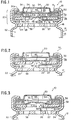
Figure 1 is a vertical sectional view through a
portion of an electrochemical cell illustrating a
safety vent valve and electrical disconnect mechanism
forming an explosion-proof disconnect assembly
constituting a preferred embodiment of the invention,
prior to cell charging.
Figure 2 is a vertical sectional view of the cell
of Figure 1 under a condition of intermediate internal
gas pressure, at level causing electrical circuit
disconnect by breaking away the vent valve contact
disk from the underlying stripper contact disk.
Figure 3 is a vertical sectional view of the cell
of Figures 1 and 2 under increased gas pressurization
of the cell to the extent of rupture of the vent valve
contact disk and gas venting of the cell interior.
Figure 4 is a schematic vertical sectional view
through a portion of an electrochemical cell
illustrating a safety vent valve and electrical
disconnect mechanism forming an explosion-proof
disconnect assembly constituting a second embodiment
of the invention.
Figure 5 is a schematic vertical sectional view
of an electrochemical cell with a safety vent valve
and electrical disconnect mechanism forming yet a
third embodiment of the invention.
Figure 6 is a top plan view of a semi-rigid
assembly cup forming a component of the cell of Figure
5.
Figure 7 is a sectional view of the assembly cup
of Figure 6.
Figure 8 is an enlarged sectional view of a
portion of the assembly cup of Figure 6.
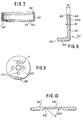
Figure 9 is a top plan view of a stripper contact
disk forming a component of the cell of Figure 5.
Figure 10 is an enlarged sectional view of a
portion of the stripper contact disk of Figure 9.
Figure 11 is a top plan view of a vent valve
contact disk forming a component of the cell of Figure
5.
Figure 12 is a sectional view of the vent valve
contact disk of Figure 10.
Figure 12a is an enlarged sectional view of the
central portion of the vent valve contact disk of
Figures 11 and 12.
Figure 13 is a top plan view of a rigid grommet
forming a component of the cell of Figure 5.
Figure 13a is a sectional view of the rigid
grommet of Figure 13.
DESCRIPTION OF THE PREFERRED EMBODIMENT
A preferred embodiment of the present invention
is described below with reference to Figs. 1, 2 and 3.
The explosion-proof electrochemical cell forming
a preferred embodiment of the invention is
illustrated generally at 10 formed of a vertically
upright cell can or container 12 sealed off by an end
cap 20 having an annular wall 50 terminating in an
outwardly directed annular flange 52. The annular
sidewall 50 is provided with one or more perforations
or holes 54 acting to vent the interior of the cell
upon rupture of the vent valve disk indicated
generally at 30. The can 12 within its sidewall 13,
adjacent the top thereof, is provided with a can bead
16 below an L-shaped, annular, soft polypropylene
grommet 36 which is captured between bead 16 and a
crimp flange 18 which defines opening 14 within the
top of the can 12. End cap 20 closes off opening 14
of can 12. A stack or assembly 23 is formed by a
stripper contact disk 28, an inverted L-shaped rigid
grommet 32, a vent valve contact disk 30, a PTC ring
34 and the inverted cup shaped end cap 20, in order
from bottom to the top, all fitted within the L-shaped
annular grommet 36. End cap 20 preferably has four
circumferentially spaced vent holes 54. A generating
element indicated generally at 22 of cylindrical form
fills the majority of the interior of the vertically
upright can or container 12, above which resides a
vapor channel forming disk 24 bearing a series of
spaced openings or perforations 38. Extending
upwardly from the electrical generating element 22 is
an aluminum anode tab indicated generally at 26 which
terminates in an offset tip 27 which extends to the
side of and in contact with the stripper contact disk
28. The stripper contact disk 28 is of metal provided
with a series of circumferentially spaced openings at
40, permitting generated gas to pass therethrough and
to enter between the upper surface of the stripper
contact disk 28 and the overlying vent valve contact
disk 30. As may be appreciated, the electrical
circuit breaker/pressure safety valve 60 of the
present invention consists primarily of a two-piece
structure sandwiched within deformed L-shaped soft
plastic grommet 36. The deformable, conductive metal,
vent valve contact disk is being welded directly at
weld point W to a reduced thickness center portion 48
of underlying stripper contact disk 28. A small mass
of metal weld material couples a flat, small diameter
circular area or portion 46 extending on the vent
valve contact disk 30 to the center of stripper
contact disk 28. Alternatively, a conical projection
46 on the lower surface of disk 30 may form a double
thickness of conductive metal such as aluminum within
the vent valve contact disk. By increasing the mass
of material at the weld point W, the strength of the
center of the vent valve contact disk is enhanced.
The disk 30 is essentially of constant thickness
throughout its diameter. The vent valve contact disk
30 includes a flat, horizontal, annular, peripheral
portion 30a joined by annular wall 30b to offset
horizontal center portion 30c. There is provided a
circumferential scored groove 37 forming a weakened
circular portion 30e which is subject to rupture upon
gas pressurization of the interior of the cell 10 to
a predefined level, well in excess of that initially
destroying the connection between the vent valve
contact disk 30 and the underlying stripper contact
disk 28 at weld point W.
In the illustrated embodiment of Figs. 1-3, it is
noted that the bottom of the underlying stripper
contact disk 28 has a circular central recess 42,
significantly diminishing the thickness of the metal
disk in an area A surrounding the weld point W.
Additionally, as indicated by dotted lines 48, there
are preferably circumferentially spaced weakened areas
at the junction of the recess 42 and the balance of
the contact disk 28 between over the full
circumference of the same. Thus, in the area of the
weld point W, the vent valve contact disk 30 is
considerably thicker than that of the underlying
stripper contact disk 28.
End cap or cover 20 may preferably be formed of
metal and may serve as the cathode terminal for the
cell, with peripheral flange 52 captured within the
crimped grommet 36. Perforations 54 within the end
cap annular wall 50 vent space 35 between disk 30 and
the end cap 20. The end cap 20 overlies the vent
valve contact disk 30, which functions as one
electrical contact for the circuit breaker or switch
60 formed by members 28 and 30 but is separated
therefrom by PTC device 34.
In effecting the assembly of the electronic
safety disconnect 10 of Fig. 1, the crimping of the
upper end of the can or container 12 about the annular
L-shaped cross-section grommet 36 deforms the soft
grommet 36 into C-shape by deflecting the upper end
36a of the grommet 36, 90°. The crimp flange 18 and
bead 16 and the end of the can 12 create a compressive
force on the stack 23, thus holding the elements at
rest in the position shown in Fig. 1. The weld at the
bottom center of the stripper contact disk 28 ensures
a low resistance electrical circuit connection between
the vent valve contact disk 30 and the stripper
contact disk 28. Preferably, the deformable vent
valve disk is resistance welded directly to the
specially designed, stamped stripper disk 28, and
being welded to the upper end 27 of the aluminum anode
tab 26, at 25. In addition to disks 28 and 30 forming
a gas pressure operated circuit breaker, the PTC
device 34 functions as a current responsive circuit
breaker to disconnect the charge circuit if the
current increases to a predetermined level within cell
10. The PTC device 34 may be a commercial product
sold by Ray Chem Corporation under the trade name
"PolySwitch".
In operation, the first embodiment, Fig. 1, prior
to developing internal gas pressure acting on the
contact vent disk 30, a low electrical resistance path
exists from aluminum anode tab 26 to the positive
potential end cap 20 via PTC element 34. In reaching
a predetermined gas pressure level internally of the
can, Fig. 2, the weld W will cause the weakened and/or
thinned portion 48 of stripper contact disk 28 to be
pulled from the thinner of the two welded disk
materials, that is the underlying stripper contact
disk 28. The center portion 48 pulls through the
balance of the stripper contact disk 28 and breaks the
stripper contact 28 at 42 and moves significantly away
from the stripper contact disk 28.
When the internal pressure generated by the
formation of gas increases significantly above that
effecting a circuit breaker action, the radially
scored or otherwise weakened portions 70 of vent valve
contact disk 30 at circumferentially spaced positions
ruptures as per Fig. 3 and the center portion 30c
takes an inverted V-shape, that is a downwardly facing
V-shape thereby moving the retained weld material and
the center portion 48 of disk 28 significantly further
away from the balance of the underlying stripper
contact disk 28. Upon rupture of the valve contact
disk 30, the relatively high pressure gas then readily
escapes through the vent ports 54 within the sidewall
50 of the inverted U-shaped end cap 20.
Fig. 4 shows a second embodiment of the invention
in which like elements to those in the first
embodiment of Figs. 1-3 bear like numerical
designations. The explosion-proof electrochemical
cell 10' forming the second embodiment of the
invention has in like fashion to cell 10 of the first
embodiment a vertically upright cell can or container
12 sealed off by an end cap 20 which is perforated to
vent the interior of the cell upon rapture of the vent
valve disk 30' configured differently from that of the
first embodiment. The can 12 within its sidewall 13
adjacent to the top thereof is provided with a can
bead 16 below an L-shaped annular soft polypropylene
grommet 36 which in similar fashion to the first
embodiment is captured between bead 16 and a crimped
flange 18 at the top of the can 12. A stack of
elements is thus captured by the crimps in the can 12
above a vapor channel forming disk 24 bearing a series
of perforations 38. The stack or assembly 23' in this
embodiment is formed from the bottom to the top by a
modified stripper contact disk 28', an electrical
insulative ring or insulator 62 which is interposed
between the stripper contact disk 28' and a flat,
relatively thin vent valve contact disk 30' adjacent
the outer peripheries of those element, a PTC ring 34
essentially identical to that of the first embodiment,
and inverted U-shaped end cap 20, again similar to
that of the first embodiment. These elements are all
fitted within the L-shaped annular grommet 36
identical to that of the first embodiment which takes
a U-shaped cross-sectional form by the can crimp
flange 18 to form a peripherally sealed assembly.
The modified stripper contact disk 28' while also
assisting in maintaining a compact stack 23', unlike
the first embodiment has a vertically raised central
portion 48 defining a weld area W facing and in direct
contact and being welded to the center portion 46' of
the overlying vent valve disk 30'. The elements 28',
30' and 34' are of the same diameter. An annular
recess 90 is formed in the upper surface of the
stripper contact disk 28' from the central weld area
48' radially outwardly to the periphery of the disk
28'. The insulator 62 has a thickness corresponding
to that recess and electrically isolates the outer
periphery of the contact disk 28' from that of the
overlying vent valve disk 30'. Contact is therefore
limited between the two disks 28' and 30' at the weld
area W. A plurality of radial grooves 70' formed in
the upper surface of the vent valve disk 30' at spaced
circumferential locations to provide a weakened area
permitting the vent valve disk to rapture upon an
internal gas pressure at a level higher than that
normally causing destruction in the area of weld W
between disks 28' and 30', with the severed, weakened
portion 48' of the stripper contact disk rupturing
from the balance of that disk and being carried away
and upwardly from the stripper contact disk 28' proper
to effect breaking of the circuit between these
components prior to rupture of the vent valve disk
30'. In similar fashion to the first embodiment, the
portion 48', which is raised relative to the balance
of the stripper contact disk 28', is thinner, and
additionally the connection between the periphery of
the circular portion 48' and the balance of the
stripper contact disk 28' is weakened by either a
continuous circular groove within the disk 28', or a
series of circumferentially spaced perforations within
that member. The operation and action is very similar
to that described with respect to the first
embodiment, both relative to the sequential breaking
of the charging circuit by pulling through the central
portion 48' of the underlying stripper contact disk
28' upon excessive pressure internally of the can in
the manner of Fig. 2 and then the rapture of the
overlying vent valve disk 30' in the area of the
grooves 70' within that member at the increasing gas
pressure level capable of causing that effect.
Additionally, the PTC element 34 acts as it does in
the first embodiment by breaking the electrical
charging circuit upon a current increase to a
predetermined level, acting much like a bimetal switch
irrespective of internal gas pressure within the can
12.
A third embodiment of the safety valve electronic
disconnect for a lithium ion rechargeable
electrochemical cell 10'' is shown in Figs. 5-13a, in
which schematically Fig. 5 illustrates the primary
elements of a combined circuit breaker and safety
valve 60'' mounted to and within the upper end of can
or container 12'' by way of a modified L-shaped cup
36'' of semirigid plastic. Elements common to the
first two embodiments are given like numeral
designations. An underlying stripper contact disk is
provided at 28''. The assembly is completed by the
upper two members of the stack, end cap 20, and the
PTC element 34, the latter two members being identical
to that of the first embodiment of Fig. 1.
Fig. 5 shows essentially the first embodiment
prior to crimping of the cell can. The difference
between the L-shaped rigid grommet and a T-shaped
rigid grommet amounts to a minor design choice. The
significant difference in the third embodiment is the
new stripper contact disk 28''. All discussions about
preassembling components within cup 36'' apply equally
to the preassembly of components within grommet 36 in
the first embodiment. Like thickened areas, as at 62a
in Fig. 8, are made in both cups 36 and 36'' for
purposes of providing a snap fit to retain components
preassembled within respective cups.
The assembly is accomplished by first placing a
deformable grommet 36 in the filled cell can 16, with
the positive electrode tab extended out and welded
onto the top vent assembly 60 and the entire assembly
stuffed back into the cell can 16 and crimp, in this
embodiment, the circuit breaker components are
assembled around a rigid annular grommet 80 which fits
internally of an assembly cup 36''. The can or
container 12'' has, in common with the first
embodiment, a can bead 16, and the top of the can is
bent over by crimping of that can top. The assembly
cup 36'', shown in detail in Figs. 6, 7 and 8 is of
molded polypropylene having initially an L-shaped
cross-section including a base 64 and an integral
right angle annular sidewall 62. Sidewall 62 includes
a thickened portion 62a, Fig. 8, of a width W''
slightly in excess of the width W' over nearly the
full height of the assembly cup sidewall. The upper
end of the sidewall 62 is tapered, having an inwardly
oblique outer edge 66 and an oppositely oblique inner
edge 68. As may be appreciated, this permits stacking
first the specially formed stripper contact disk 28''
acting to sandwich one side of the T-shaped cross-section
rigid electrically insulative grommet 80
between that member and a specially formed vent valve
contact disk 30'', above both of which, there resides
a thin circular PTC element 34 and the overlying
inverted U-shaped end cap 20 having a radially outward
flange. Both members 20 and 34 have outer diameters
which are on the order of the inner diameter of the
thickened portion 62a of the assembly cup 36''
sidewall 62. This permits the circuit breaker
components 28'', 30'' to be assembled about or above
the rigid grommet 80 and initially held within the L-shaped
cross-section annular assembly 36'' fitted to
the interior of the cell can 12' above the crimp 16,
Fig. 4. The assembly cup 36'' has a circular opening
65 within its base 64.
Figs. 9 and 10 show the makeup of the stripper
contact disk 28'' of the third embodiment, Fig. 5.
The disk 28'', as shown in the plan view of Fig. 9,
includes a plurality of circumferentially spaced holes
or openings 40'' similar to that of the stripper
contact disk 28' of the second embodiment. The new
stripper contact disk 28'' design uses oval C-shaped
slots 40'' spaced on a diameter generally equal to the
diameter of the circular score line 42''. There is a
reduced thickness central portion 48'' within the
bottom of the disk 28' defined partially by a circular
score line which ensures that the thickness of the
lower stripper contact disk 28'' is considerably less
than that of the center of overlying vent valve
contact disk 30'' of Figs. 11, 12 and 12a. This
ensures that a weld nugget 44'', Fig. 5, will remain
integrated to and rise with the center of vent valve
disk 30'' during an initial circuit breaker disconnect
action similar to that of the first embodiment, with
the weld nugget 44'' separating from the disk 28''
while preferably carrying along a reduced thickness
weakened portion 48''a of the stripper contact disk
28''. Alternatively, a weld director projection of
the central portion 30''e may be struck from disk 28''
to rigidify and strengthen the disk 28'' at weld point
W. The unitary vent valve contact disk 30'', Fig.
11, is of cup shape form, having an outer annular
flange 30''a and being generally of uniform thickness
over its full diameter. It includes a vertically
stepped sidewall 30''b intermediate of a central
portion 30''c and the radially outer flange 30''a. As
shown in the enlarged sectional view of Fig. 12a, a
central portion 30''e is formed by a small diameter
circular indentation in the top face of the vent valve
contact disk 30''. Preferably, cruciform score lines
70'' radiating outwardly from the outer periphery of
the central portion 30''e in the direction of the
sidewall 30''b within the upper face of the disk 30'
create lines of weakness to facilitate the radial line
severance of the disk 30'' to effect rupturing of the
seal when the vent valve contact disk, employed in the
stacked array of Fig. 5, is subject to excessive gas
pressure. The disk 30'' may be formed of a 1100
series aluminum alloy. Disk 30'' is similar, if not
identical to disk 30 of the first embodiment.
In this third embodiment, the disconnect assembly
60'' incorporates a molded rigid ABS/NYLON or
polypropylene rigid grommet 80 of T-shape cross-section,
Figs. 12 and 12a, including a circular
sidewall 82 integral with an inwardly projecting
central projection 84 of rectangular cross-section.
The projection 84 forms a relatively small inside
diameter peripheral wall 86 and an outside diameter
peripheral wall 88. The vertical height of the
annular rigid grommet 80, Fig. 13a, is substantially
larger than the thickness of the radially inward
projection 84. The outside diameter 88 of the T-shaped
cross-section rigid grommet 80 is sized to the
inside diameter of the L-shaped cross-section assembly
cup 36'' within which a stack of elements rests by
pressing elements 28'', 80, 30'', 34 and 20 in
ascending order downwardly into the interior of the
can or container 12' through the open top and over the
thickened terminal portion 62a of the vertical
sidewall of the cup shaped assembly cup 36''. The
rigid grommet alternatively may be of L-shaped cross-section.
In this embodiment, an aluminum tab is preferably
prewelded or otherwise attached to the bottom of the
stripper contact disk. The separate assembly cup 36''
permits ready insertion of the stack of elements into
the same prior to crimping of the can 12' top.
As may be appreciated, the several embodiments of
the invention therefore provide simplified structures
which are compact and have components which are easily
manufactured to ensure an excellent, low electrical
resistance current path to the positive end cap 20.
Further, by providing circumferentially spaced slits
within the center of the stripper contact disk
adjacent to the weld nugget or by scoring circularly
about the weld attachment point, the weld may be
maximized while not becoming the ultimate point of
electrical disconnect. The adjacent scored and
preferably thinner section of the stripper contact
disks 28, 28' and 28'' achieves a mechanical break
similar to that of the LiSO2 vents, with the break at
scored section being carefully controlled by varying
depths of the score line about the desired area of
disconnect.
As may be appreciated from the above description
with respect to the three embodiments illustrating the
compact nature of the explosion-proof valve disconnect
assembly, this invention provides definite advantages
in ease of assembly, ease and reliability of the
necessary welds between the vent valve contact disk
and the underlying stripper contact disk, as well as
that between the anode tab and the weld tab integral
with and stamped from the stripper contact disk or
alternatively welded to the bottom face of the same as
significant improvements within this art.
It should be understood that while the foregoing
description is directed to several preferred
embodiments, modifications may be made to the
individual components and Components from the
respective embodiments may interchanged where
appropriate, as well as in the type of material,
structural content and stamping of the same without
departing from the spirit and scope of the present
invention. The foregoing description of the preferred
embodiments are illustrative only and the limitations
of the present invention are by way of the claims set
forth below.