EP0818675A2 - Method and device for spectral remission measurement - Google Patents
Method and device for spectral remission measurement Download PDFInfo
- Publication number
- EP0818675A2 EP0818675A2 EP97110961A EP97110961A EP0818675A2 EP 0818675 A2 EP0818675 A2 EP 0818675A2 EP 97110961 A EP97110961 A EP 97110961A EP 97110961 A EP97110961 A EP 97110961A EP 0818675 A2 EP0818675 A2 EP 0818675A2
- Authority
- EP
- European Patent Office
- Prior art keywords
- measuring
- radiation
- light source
- spectral
- lighting device
- Prior art date
- Legal status (The legal status is an assumption and is not a legal conclusion. Google has not performed a legal analysis and makes no representation as to the accuracy of the status listed.)
- Granted
Links
- 230000003595 spectral effect Effects 0.000 title claims abstract description 67
- 238000000034 method Methods 0.000 title claims description 17
- 238000005259 measurement Methods 0.000 title abstract description 26
- 238000009826 distribution Methods 0.000 claims abstract description 37
- 230000005855 radiation Effects 0.000 claims abstract description 30
- 238000006243 chemical reaction Methods 0.000 claims abstract description 6
- 238000012545 processing Methods 0.000 claims abstract description 6
- 238000007639 printing Methods 0.000 claims description 30
- 238000011156 evaluation Methods 0.000 claims description 15
- 238000005286 illumination Methods 0.000 claims description 10
- 239000000463 material Substances 0.000 claims description 9
- 230000001419 dependent effect Effects 0.000 claims description 3
- 230000008569 process Effects 0.000 claims description 3
- 230000001678 irradiating effect Effects 0.000 claims 1
- 238000001514 detection method Methods 0.000 abstract description 4
- 230000003116 impacting effect Effects 0.000 abstract 1
- 238000001228 spectrum Methods 0.000 description 10
- 239000000758 substrate Substances 0.000 description 5
- TZCXTZWJZNENPQ-UHFFFAOYSA-L barium sulfate Chemical compound [Ba+2].[O-]S([O-])(=O)=O TZCXTZWJZNENPQ-UHFFFAOYSA-L 0.000 description 4
- 230000008859 change Effects 0.000 description 4
- 230000007935 neutral effect Effects 0.000 description 4
- 230000003287 optical effect Effects 0.000 description 4
- 238000004422 calculation algorithm Methods 0.000 description 3
- 238000003908 quality control method Methods 0.000 description 3
- 230000006978 adaptation Effects 0.000 description 2
- 238000012937 correction Methods 0.000 description 2
- 238000009795 derivation Methods 0.000 description 2
- 239000000976 ink Substances 0.000 description 2
- 230000010354 integration Effects 0.000 description 2
- 238000004886 process control Methods 0.000 description 2
- 230000035945 sensitivity Effects 0.000 description 2
- 238000010183 spectrum analysis Methods 0.000 description 2
- 230000004913 activation Effects 0.000 description 1
- 238000004458 analytical method Methods 0.000 description 1
- 238000013459 approach Methods 0.000 description 1
- 230000008901 benefit Effects 0.000 description 1
- 230000005540 biological transmission Effects 0.000 description 1
- 238000004364 calculation method Methods 0.000 description 1
- 230000008878 coupling Effects 0.000 description 1
- 238000010168 coupling process Methods 0.000 description 1
- 238000005859 coupling reaction Methods 0.000 description 1
- 238000011161 development Methods 0.000 description 1
- 230000018109 developmental process Effects 0.000 description 1
- 230000000694 effects Effects 0.000 description 1
- 230000005611 electricity Effects 0.000 description 1
- 238000005516 engineering process Methods 0.000 description 1
- 230000006870 function Effects 0.000 description 1
- 229910052736 halogen Inorganic materials 0.000 description 1
- 150000002367 halogens Chemical class 0.000 description 1
- 238000007689 inspection Methods 0.000 description 1
- 238000011835 investigation Methods 0.000 description 1
- 238000000691 measurement method Methods 0.000 description 1
- 239000000203 mixture Substances 0.000 description 1
- 238000007645 offset printing Methods 0.000 description 1
- 238000012549 training Methods 0.000 description 1
- 238000011144 upstream manufacturing Methods 0.000 description 1
Images


Classifications
-
- B—PERFORMING OPERATIONS; TRANSPORTING
- B41—PRINTING; LINING MACHINES; TYPEWRITERS; STAMPS
- B41F—PRINTING MACHINES OR PRESSES
- B41F33/00—Indicating, counting, warning, control or safety devices
- B41F33/0081—Devices for scanning register marks
-
- G—PHYSICS
- G01—MEASURING; TESTING
- G01N—INVESTIGATING OR ANALYSING MATERIALS BY DETERMINING THEIR CHEMICAL OR PHYSICAL PROPERTIES
- G01N21/00—Investigating or analysing materials by the use of optical means, i.e. using sub-millimetre waves, infrared, visible or ultraviolet light
- G01N21/17—Systems in which incident light is modified in accordance with the properties of the material investigated
- G01N21/25—Colour; Spectral properties, i.e. comparison of effect of material on the light at two or more different wavelengths or wavelength bands
- G01N21/27—Colour; Spectral properties, i.e. comparison of effect of material on the light at two or more different wavelengths or wavelength bands using photo-electric detection ; circuits for computing concentration
- G01N21/274—Calibration, base line adjustment, drift correction
-
- G—PHYSICS
- G01—MEASURING; TESTING
- G01N—INVESTIGATING OR ANALYSING MATERIALS BY DETERMINING THEIR CHEMICAL OR PHYSICAL PROPERTIES
- G01N21/00—Investigating or analysing materials by the use of optical means, i.e. using sub-millimetre waves, infrared, visible or ultraviolet light
- G01N21/84—Systems specially adapted for particular applications
- G01N21/88—Investigating the presence of flaws or contamination
- G01N21/89—Investigating the presence of flaws or contamination in moving material, e.g. running paper or textiles
- G01N21/8901—Optical details; Scanning details
-
- G—PHYSICS
- G01—MEASURING; TESTING
- G01J—MEASUREMENT OF INTENSITY, VELOCITY, SPECTRAL CONTENT, POLARISATION, PHASE OR PULSE CHARACTERISTICS OF INFRARED, VISIBLE OR ULTRAVIOLET LIGHT; COLORIMETRY; RADIATION PYROMETRY
- G01J3/00—Spectrometry; Spectrophotometry; Monochromators; Measuring colours
- G01J3/28—Investigating the spectrum
- G01J2003/2866—Markers; Calibrating of scan
-
- G—PHYSICS
- G01—MEASURING; TESTING
- G01J—MEASUREMENT OF INTENSITY, VELOCITY, SPECTRAL CONTENT, POLARISATION, PHASE OR PULSE CHARACTERISTICS OF INFRARED, VISIBLE OR ULTRAVIOLET LIGHT; COLORIMETRY; RADIATION PYROMETRY
- G01J3/00—Spectrometry; Spectrophotometry; Monochromators; Measuring colours
- G01J3/02—Details
- G01J3/10—Arrangements of light sources specially adapted for spectrometry or colorimetry
-
- G—PHYSICS
- G01—MEASURING; TESTING
- G01J—MEASUREMENT OF INTENSITY, VELOCITY, SPECTRAL CONTENT, POLARISATION, PHASE OR PULSE CHARACTERISTICS OF INFRARED, VISIBLE OR ULTRAVIOLET LIGHT; COLORIMETRY; RADIATION PYROMETRY
- G01J3/00—Spectrometry; Spectrophotometry; Monochromators; Measuring colours
- G01J3/46—Measurement of colour; Colour measuring devices, e.g. colorimeters
- G01J3/50—Measurement of colour; Colour measuring devices, e.g. colorimeters using electric radiation detectors
Abstract
Description
Die Erfindung betrifft ein Verfahren sowie eine Vorrichtung zur Erfassung spektraler Remissionen gemäß dem Oberbegriff des Verfahrens- bzw. Vorrichtungsanspruches.The invention relates to a method and a device for detection spectral remissions according to the generic term of the process or Device claim.
Bei Druckmaschinen, insbesondere Bogenoffsetdruckmaschinen ist es bekannt, zur Qualitätskontrolle mittels vorzugsweise innerhalb der Maschine angeordneter Meßeinrichtungen Remissions-Istwerte zu erfassen und daraus Qualitätsdaten bzw. Stellgrößen für die Prozeßsteuerung abzuleiten. Dabei finden insbesondere Densitometer/spektrale Densitometer, Farbmeßgeräte bzw. sogenannte Spektralfotometer Verwendung. Bei den letztgenannten Meßeinrichtungen ist es dabei als vorteilhaft anzusehen, daß mittels dieser Meßgeräte das beispielsweise im sichtbaren Bereich gelegene Licht einer Meßstelle spektral analysiert und durch digitale Weiterverarbeitung hinsichtlich verschiedener Kriterien analysiert werden kann. So ist es beispielsweise möglich, aus den spektralen Remissionen einer Meßstelle durch digitale Wichtung sowohl die in der Drucktechnik schon seit langer Zeit verwendeter Farbdichtewerte als auch farbmetrische Maßzahlen entsprechend der spektralen Verteilungskurven des CIE-Normalbeobachters abzuleiten. Die zuvorstehend beschriebenen Remissionsmeßwerte (densitometrisch, farbmetrisch, spektral) können dabei sowohl an speziell gestalteten und extra mitgedruckten Meßfeldern als auch an beliebig auswählbaren Meßstellen im Sujet (dem eigentlichen Bild) gewonnen werden. Letzteres hat dabei den Vorteil, daß nicht zusätzlicher Raum auf dem Bedruckstoff benötigt wird und ferner die Ableitung von Qualitäts- bzw. Prozeßsteuerdaten direkt am eigentlichen Druckprodukt erfolgt.In printing machines, in particular sheetfed offset printing machines, it is known for quality control by means of preferably arranged inside the machine Measuring devices to record actual remission values and quality data therefrom or derive manipulated variables for process control. In particular, find Densitometers / spectral densitometers, color measuring devices or so-called Spectrophotometer use. It is with the latter measuring devices to be regarded as advantageous that, for example, by means of these measuring devices Light from a measuring point located in the visible range is spectrally analyzed and transmitted digital processing can be analyzed according to various criteria can. So it is possible, for example, from the spectral remissions of a Measuring point through digital weighting both in printing technology for a long time Time used color density values as well as colorimetric measurements accordingly the spectral distribution curves of the CIE normal observer. The reflectance measurements described above (densitometric, colorimetric, spectral) can be both on specially designed and specially printed Measuring fields as well as at any selectable measuring points in the subject (the actual image) can be obtained. The latter has the advantage that not additional Space on the substrate is required and also the derivation of Quality or process control data is made directly on the actual print product.
Bei Meßvorrichtungen, vermittels derer insbesondere spektrale Remissionsdaten direkt innerhalb der laufenden Maschine gewonnen werden, ist eine Anpassung der Sensorempfindlichkeit, der Beleuchtungsstärke sowie der Meßfeldgröße aufeinander nötig. Gerade bei sehr schnellaufenden Druckmaschinen stehen bei gegebener Meßfeldgröße (Millimeterbereich) und einer maximal erzielbaren Beleuchtungsstärke nur bestimmte Meßzeiten zur Verfügung, innerhalb derer die Sensorik eines insbesondere spektralen Remissionsmeßgerätes die empfangene Lichtmenge zu wandeln hat. Dies bedeutet, daß die Meßfleckgeometrie abhängig ist von der Meßblendengeometrie, der Relativgeschwindigkeit Bedruckstoff/Meßfeld gegenüber Meßgerät sowie der Integrationszeit des bzw. der Sensoren. Den Auswirkungen einer Veränderung der Relativgeschwindigkeit des Bedruckstoffes nebst Meßfeld relativ zum Meßgerät (Druckgeschwindigkeit) kann innerhalb gegebener Grenzen durch Verändern der Integrationszeit der Sensorik entgegengewirkt werden. Der gesamte Bereich der Relativgeschwindigkeit Bedruckstoff - Meßgerät (Druckgeschwindigkeit) wird dadurch aber nicht abgedeckt. Um den Aussteuerungs(Dynamik)-Bereich des Sensorsystems voll auszunutzen und damit auch ein Einhalten der gewählten Genauigkeitsklasse zu erzielen, ist es notwendig, zusätzlich auch die Beleuchtungsintensität zu verändern. Bei hohen Druckgeschwindigkeiten muß also ein Meßfeld vorgegebener Größe mit mehr Licht beaufschlagt werden als bei geringeren Druckgeschwindigkeiten.In the case of measuring devices, by means of which, in particular, spectral reflectance data to be gained directly while the machine is running is an adjustment the sensor sensitivity, the illuminance and the measuring field size necessary to each other. Especially in the case of very fast printing presses given measuring field size (millimeter range) and a maximum achievable Illuminance only certain measuring times available, within which the Sensor system of a spectral reflectance measuring device, in particular, the received one Has to change the amount of light. This means that the spot geometry depends is of the orifice geometry, the relative speed Printing material / measuring field compared to measuring device and the integration time of the Sensors. The effects of a change in the relative speed of the Printing material and measuring field relative to the measuring device (printing speed) can within given limits by changing the integration time of the sensors be counteracted. The entire range of relative speed Printing material measuring device (printing speed) will not covered. Around the dynamic range of the sensor system to exploit and thus also to adhere to the selected accuracy class achieve, it is necessary to also increase the lighting intensity change. At high printing speeds, a measuring field must be used specified size are exposed to more light than at lower printing speeds.
Aus der EP 0 378 283 B1 ist eine Meßvorrichtung für die Qualitätsinspektion des gedruckten Materials bekannt, bei welcher in Abhängigkeit der Druckgeschwindigkeit ein sogenanntes Neutralgraufilter mit sich stetig ändernder Schwärzung der Transmission im Beleuchtungsstrahlengang der Meßfeldbeleuchtung verfahren wird. Dem Neutralgraufilter mit sich stetig ändernder Schwärzung ist dazu ein fernansteuerbarer Antrieb zugeordnet, der seine Signale von einer Steuerung erhält. Diese Steuerung steht mit einem die Geschwindigkeit der Druckmaschine erfassenden Gebersystem in Signalverbindung, um entsprechend der Druckgeschwindigkeit das Neutralgraufilter zu verfahren. Damit wird erreicht, daß mittels dieser Meßeinrichtung Meßfelder gegebener Größe bei gleichbleibend angesteuerter Beleuchtungseinrichtung bei unterschiedlichen Druckgeschwindigkeiten stets im optimalen Bereich der Sensorempfindlichkeit abgetastet werden können. Nachteilig ist hierbei aber, daß eine insbesondere durch zusätzliche bewegte Teile aufwendige, gegen mechanische Störeinflüsse empfindliche und auch der Verschmutzung ausgesetzte Lichtsteuereinrichtung in Form des verfahrbaren Neutralgraufilters nötig ist.EP 0 378 283 B1 describes a measuring device for the quality inspection of the printed material known, depending on the printing speed a so-called neutral gray filter with constantly changing blackening of the Transmission in the illumination beam path the measuring field lighting is moved. The neutral gray filter with itself steadily changing blackening is associated with a remotely controllable drive that receives its signals from a controller. This control is available with a Speed of the encoder system detecting the press Signal connection to the according to the printing speed To move neutral gray filter. This ensures that by means of this Measuring device measuring fields of a given size with constant control Illumination device always at different printing speeds optimal range of sensor sensitivity can be scanned. Disadvantageous but here is that one in particular by additional moving parts elaborate, sensitive to mechanical interference and also the Contaminated light control device in the form of the movable Neutral gray filter is necessary.
Aus der WO 95/00335 A1 ist es bekannt, zur Anpassung mehrerer Beleuchtungsquellen an die gleiche Farbtemperatur sogenannte Eichmessungen durchzuführen, bei welchen das jeweilige Meßsystem auf einen sogenannten Eichstandard (Weißstandard) eingemessen wird. Es erfolgt hierbei eine Verarbeitung der Farbtemperatur der Beleuchtungseinrichtung der jeweiligen Meßvorrichtung bzw. ein die Farbtemperatur wiedergebendes Maß der spektralen Energieverteilung der Beleuchtungseinrichtung mit den gemessenen fotometrischen Größen. Die beschriebene Verfahrensweise sowie die entsprechenden Vorrichtungen finden ebenfalls bei Meßeinrichtungen innerhalb einer Druckmaschine Verwendung, bei welchen eine Relativgeschwindigkeit des Bedruckstoffes gegenüber der Meßeinrichtung vorliegt.From WO 95/00335 A1 it is known to adapt multiple lighting sources to carry out so-called calibration measurements at the same color temperature, in which the respective measuring system is based on a so-called calibration standard (White standard) is measured. The color temperature is processed here the lighting device of the respective measuring device or a the color temperature reflecting measure of the spectral energy distribution of the lighting device with the measured photometric quantities. The one described Find the procedure and the corresponding devices also used in measuring devices within a printing press which a relative speed of the printing material compared to the Measuring device is present.
Aus der DE 40 13 422 A1 ist eine Beleuchtungseinrichtung für ein Farbmeßgerät bekannt, bei der zusätzliche Meßwandler zur Erfassung der von einer Halogenlampe erzeugten Strahlung vorgesehen sind. Die Meßsignale der Meßwandler werden dazu verwendet, um über das Verändern der Lampenspannung eine vorgegebene Soll-Farbtemperatur der Beleuchtungsstrahlung zu erzielen.DE 40 13 422 A1 describes an illumination device for a color measurement device known in the additional transducer for detecting the from a Halogen lamp generated radiation are provided. The measurement signals of the Transducers are used to keep track of changing the Lamp voltage a predetermined target color temperature To achieve illuminating radiation.
Aufgabe der vorliegenden Erfindung ist es daher, ein Verfahren sowie eine entsprechende
Vorrichtung gemäß dem Oberbegriff von Anspruch 1 bzw. 8 derartig
weiterzubilden, so daß unter Vermeidung der voranstehend genannten Nachteile
eine optimale Anpassung des optischen Remissionsmeßsystems an unterschiedliche
Druckgeschwindigkeiten bei vorgegebener Meßfeldgröße möglich ist.The object of the present invention is therefore a method and a corresponding one
Device according to the preamble of
Gelöst wird diese Aufgabe durch die kennzeichnenden Merkmale des Verfahrens- bzw. Vorrichtungsanspruches. Weiterbildungen der Erfindung ergeben sich aus den jeweiligen Unteransprüchen. This task is solved by the characteristic features of the process or Device claim. Further developments of the invention result from the respective subclaims.
Gemäß der Erfindung ist allgemein vorgesehen, daß in Abhängigkeit der Relativgeschwindigkeit des Bedruckstoffes nebst Meßfeld bezüglich der Meßeinrichtung eine die Beleuchtungsstärke/Beleuchtungsintensität der Lichtquelle direkt beeinflussende Größe variiert wird, in dem Sinne, daß bei hohen Relativgeschwindigkeiten eine höhere Beleuchtungsstärke/Beleuchtungsintensität erzeugt wird als bei niedrigen Relativgeschwindigkeiten, daß die bei der vorliegenden Beleuchtungsintensität/Beleuchtungsstärke sich ergebene spektrale Energieverteilung ermittelt wird, und daß diese ermittelte spektrale Energieverteilung des Beleuchtungslichtes bei der jeweilig vorliegenden Beleuchtungsstärke/Beleuchtungs-Intensität in Verbindung mit dem von der Meßstelle remittierten und im fotoelektrischen Wandler empfangenen Licht bei der Auswertung mit verarbeitet wird, in dem Sinne, daß die sich bei unterschiedlichen Beleuchtungsstärken/Beleuchtungsintensitäten ergebenen unterschiedlichen spektralen Energieverteilungen des Beleuchtungslichtes herausgerechnet werden.According to the invention it is generally provided that depending on the relative speed of the substrate and measuring field with respect to the measuring device a directly the illuminance / illuminance of the light source influencing size is varied, in the sense that at high relative speeds generates a higher illuminance / intensity is considered that at low relative speeds, that at the present illuminance / illuminance resulting spectral Energy distribution is determined, and that this determined spectral Energy distribution of the illuminating light in the present case Illuminance / illumination intensity in connection with that remitted by the measuring point and light received in the photoelectric converter during the evaluation is processed in the sense that the different illuminance levels / intensities result in different spectral energy distributions of the illuminating light.
Die vorliegende Erfindung läßt sich dabei verfahrens- und vorrichtungsmäßig in einer Vielzahl von Varianten durchführen. So kann es möglich sein, die Spannung und/oder die Stromstärke der wenigstens eine Glühlampe aufweisenden Beleuchtungseinrichtung in Abhängigkeit der Druckgeschwindigkeit entweder kontinuierlich bzw. innerhalb bestimmter Druckgeschwindigkeitsbereichen gestuft zu verändern bzw. mehrere Glühlampen insbesondere unterschiedlicher Leistung in vorgegebener Weise zuzuschalten. Durch Auskoppeln von Licht der Beleuchtungseinrichtung (z. B. halbdurchlässiger Spiegel bzw. Blendenspiegel) wird ein Teil der Strahlung der Beleuchtungseinrichtung auf eine spezielle Referenzmeßsensorik abgeleitet, durch welche in zwei oder mehreren spektralen Bereichen eine Erfassung der spektralen Intensitätsverteilung der durch die Beleuchtungseinrichtung erzeugten Strahlung erfolgt. Hierbei kann es ausreichend sein, daß die Referenzsensorik die Strahlung der Beleuchtungseinrichtung bspw. in drei spektralen Bereichen analysiert, wobei eine Interpolation der spektralen Energieverteilung über die Stützstellen erfolgt. Das derartig ermittelte Beleuchtungsspektrum/die spektrale Energieverteilung der Beleuchtungseinrichtung wird dann bei der Auswertung des von der eigentlichen Meßstelle reflektierten Lichtes mitberücksichtigt, in dem Sinne, daß die bei unterschiedlichen Beleuchtungsstärken gegebenen unterschiedlichen spektralen Energieverteilungen auf eine einheitliche Beleuchtungsstärke und somit gegebener spektraler Energieverteilung umgerechnet werden (z.B. Normlichtart).The present invention can be procedurally and device-wise in perform a variety of variants. So it may be possible to get the tension and / or the current intensity of the lighting device having at least one incandescent lamp depending on the printing speed either continuously or to change within certain print speed ranges or several light bulbs in particular of different wattages to connect in a predetermined manner. By decoupling light from the Lighting device (e.g. semi-transparent mirror or diaphragm mirror) part of the radiation from the lighting device is directed to a special Reference measurement sensors derived, by which in two or more spectral Areas of detection of the spectral intensity distribution through the Radiation generated radiation takes place. It can be enough be that the reference sensor system emits the radiation from the lighting device, for example in analyzed three spectral ranges, with an interpolation of the spectral Energy is distributed across the support points. The so determined Lighting spectrum / the spectral energy distribution of the lighting device is then used in the evaluation of the actual Measuring point of reflected light also taken into account, in the sense that the at different illuminance given different spectral Energy distributions to a uniform illuminance and thus given spectral energy distribution can be converted (e.g. standard illuminant).
Eine zweite verfahrensmäßige Vorgehensweise ergibt sich, wenn in dem Auskopplungsstrahlengang zur Referenzmessung zwecks Bestimmung der spektralen Energieverteilung der Beleuchtungseinrichtung ein sogenannter Weißstandard in Form eines Probeplättchens (beispielsweise Bariumsulfat) angeordnet ist. Bei dieser Vorgehensweise wird gleichzeitig mit dem Erfassen der spektralen Remission des Meßfeldes eine sogenannte Weißreferenzmessung durchgeführt, wobei die sich bei unterschiedlichen Beleuchtungsstärken ergebenden spektralen Intensitätsveränderungen des Beleuchtungslichtes mitberücksichtigt werden. Auch in diesem Falle wird das von der Meßfläche (Meßfeld) remittierte Licht nach entsprechender fotoelektrischer Wandlung durch das Meßsystem in Verbindung mit dieser die spektrale Intensitätsverteilung wiedergegebenen Weißreferenzmessung dahingehend verrechnet, daß Meßwerte erhalten werden, welche einer stets gleichbleibenden Beleuchtungsstärke nebst spektraler Energieverteilung entsprechen. Eine derartige Referenzmessung in Verbindung mit einem Weißstandard (z. B. Bariumsulfat) ist dabei insbesondere bei der Erfassung von farbmetrischen Meßwerten bzw. spektralen Meßwerten zur farbmetrischen Weiterverarbeitung sinnvoll.A second procedural procedure arises when in the coupling beam path for reference measurement in order to determine the spectral energy distribution the lighting device a so-called white standard in the form a sample plate (for example barium sulfate) is arranged. At this The procedure is carried out at the same time as the spectral reflectance of the Measuring field carried out a so-called white reference measurement, the with spectral intensity changes resulting in different illuminance levels of the illuminating light are also taken into account. Also in In this case, the light remitted by the measuring surface (measuring field) becomes after corresponding photoelectric conversion in connection with the measuring system with this reproduced the spectral intensity distribution White reference measurement calculated so that measured values are obtained which always has a constant illuminance and spectral Energy distribution. Such a reference measurement in connection with A white standard (e.g. barium sulfate) is particularly important when recording from colorimetric measurement values or spectral measurement values to colorimetric Further processing makes sense.
Vorrichtungsgemäß kann vorgesehen sein, daß zur Erfassung der spektralen Intensitätsverteilung der Beleuchtungseinrichtung das gleiche spektrale Meßsystem Verwendung findet, wie dasjenige System, vermittels dem die vom Meßfeld (Bedruckstoff) remittierte Strahlung fotoelektrisch gewandelt wird. Insbesondere kann es sich hierbei um einen CCD-Zeilen/Flächensensor handeln, der nebst entsprechend optischer Vorschaltung bspw. eines Beugungsgitters zu einem Spektralmeßsystem erweitert worden ist. Alternativ dazu ist es ebenfalls möglich, zur Erfassung der spektralen Intensitätsverteilung des Beleuchtungslichtes lediglich ein grob auflösendes spektrales Meßsystem zu verwenden, beispielsweise eine die Beleuchtungsstrahlung in einem roten, in einem grünen und in einem blauen Bereich analysierende und quantitativ bewertende Sensorik. Es ergeben sich bei einem derartigen Analysesystem für das gesamte Spektrum der Beleuchtungseinrichtung insgesamt drei Meßwerte, aus denen dann rechnerisch durch Interpolation unter Zugrundelegung von die spektralen Charakteristika der Beleuchtungseinrichtung berücksichtigender Algorithmen die spektrale Energieverteilung der Beleuchtungseinrichtung ermittelbar ist. Auch in diesem Falle wird die mittels bestimmter Algorithmen ermittelte spektrale Intensitätsverteilung der Beleuchtungseinrichtung in Verbindung mit der das remittierte Licht des Meßfeldes erfassenden Sensorik zur Berechnung der Meßwerte auf einen festen Beleuchtungswert (Normierung) verwendet.According to the device it can be provided that for the detection of the spectral Intensity distribution of the lighting device the same spectral Measuring system is used, like the system by means of which the Measuring field (printing material) remitted radiation is converted photoelectrically. In particular, this can be a CCD line / area sensor, which, in addition to the corresponding optical ballast, for example a diffraction grating a spectral measuring system has been expanded. Alternatively, it is too possible to record the spectral intensity distribution of the Illumination light only a roughly resolving spectral measuring system use, for example the illuminating radiation in a red, in a green and a blue analyzing and quantitative evaluating sensors. In such an analysis system, the result for the entire spectrum of the lighting device a total of three measured values which are then calculated by interpolation based on the taking into account spectral characteristics of the lighting device Algorithms the spectral energy distribution of the lighting device can be determined. In this case too, the algorithm is used determined spectral intensity distribution of the lighting device in Connection to the sensor system detecting the remitted light of the measuring field Calculation of the measured values to a fixed lighting value (standardization) used.
In den beiden zuvorstehend skizzierten Fällen hinsichtlich der Ausführung des erfindungsgemäßen Meßverfahrens wird dabei die Erkenntnis genutzt, daß die spektrale Energieverteilung (bezogen auf die Wellenlänge des Lichtes) des durch eine Beleuchtungseinrichtung erzeugt und von einem Meßfeld reflektierten (remittierten) Lichtes mathematisch dargestellt werden kann als das Produkt des Beleuchtungsspektrums sowie der spektralen Reflexion (Remissionscharakteristik/Remissionsgrad) der reflektierenden Fläche bzw. der Meßfläche (Bedruckstoff plus Druckfarbenauftrag). Wird mit
- b
- (λ) die spektrale Intensitätsverteilung des Beleuchtungslichtes, mit
- r
- (λ) der spektrale Reflektionsgrad des Meßfeldes, und mit
- M
- (λ) die spektrale Intensitätsverteilung des vom Meßfeld reflektierten und durch
das Meßsystem empfangenen Lichtes bezeichnet, so gilt:
- b
- (λ) the spectral intensity distribution of the illuminating light, with
- r
- (λ) the spectral reflectance of the measuring field, and with
- M
- (λ) denotes the spectral intensity distribution of the light reflected from the measuring field and received by the measuring system, the following applies:
Da vorgesehen ist, bei unterschiedlichen Druck- bzw. Relativgeschwindigkeiten v
unterschiedliche Beleuchtungsstärken bv(λ) durch entsprechendes Ansteuern der
Beleuchtungseinrichtung des Meßsystems zu verwenden, ergeben sich für unterschiedliche
Relativgeschwindigkeiten v unterschiedliche spektrale Intensitätsverteilungen
des durch das Meßsystem empfangenden Lichtes Mv(λ). Allgemein gilt also
für diesen Fall:
Dieser Ansatz geht dabei davon aus, daß der spektrale Reflektionsgrad r (λ) der Meßfläche unabhängig von der Beleuchtungsstärke bzw. von der spektralen Intensitätsverteilung des Beleuchtungslichtes ist, was bei den üblicherweise verwendeten Druckfarben/Bedruckstoffen hinreichend genau zutrifft.This approach assumes that the spectral reflectance r (λ) of the Measuring area independent of the illuminance or the spectral Intensity distribution of the illuminating light is what is usual with the the printing inks / substrates used are sufficiently accurate.
Gemäß dem oben aufgezeigten Formelzusammenhang ist die spektrale
Energieverteilung bv(λ) des Beleuchtungslichtes eine Funktion der Druck- bzw.
Relativgeschwindigkeit v, so daß sich bei unterschiedlichen Beleuchtungsstärken
und somit unterschiedlichen spektralen Zusammensetzungen des
Beleuchtungslichtes bv(λ) unterschiedliche Meßspektren Mv(λ) und somit auch
unterschiedliche bspw. farbmetrische bzw. densitometrische Bewertungen des
Meßlichtes ergeben. Um zu einer von der Relativgeschwindigkeit v unabhängigen
Bewertung des vom Meßfeld reflektierten Meßlichtes M (λ) zu gelangen, ist es
lediglich nötig, folgende Umrechnung durchzuführen:
Setzt man kv (λ) := b (λ)/bv(λ), so ergibt sich:
Bei unterschiedlichen Relativgeschwindigkeiten v erhält man also trotz
unterschiedlicher Beleuchtungsintensitäten bzw. Spektren bv(λ) ein auf eine
Beleuchtungsstärke bzw. damit verbundenes Spektrum b (λ) bezogenes Spektrum
des vom Meßfeldes reflektierten Lichtes M (λ) durch Verwendung einer
geschwindigkeitsabhängigen Korrekturgröße kv(λ), wobei diese eine von der
aktuellen Relativgeschwindigkeit v abhängige Intensitätsverteilung bv(λ) des
Beleuchtungslichtes enthält. Bei jeder Messung werden Mv(λ) und bv(λ) erfaßt, so
daß mit einem gespeicherten Spektrum b (λ) die Korrekturgröße kv(λ) bestimmbar
und somit das auf eine einheitliche Beleuchtungsart bezogene Meßspektrum M (λ)
ermittelbar ist:
Des weiteren erfolgt die Erläuterung von Ausführungsbeispielen der Erfindung anhand der Zeichnungen. Hierbei zeigen die Fig. 1 - 4 jeweils eine vorrichtungsgemäße Ausbildung des erlindungsgemäßen Meßprinzips.Furthermore, exemplary embodiments of the invention are explained with reference to of the drawings. 1-4 each show a device according to the device Training of the measuring principle according to the invention.
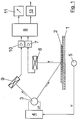
Ein mit der Geschwindigkeit v relativ zu dem in Figur 1 angedeuteten Meßsystem bewegtes
auf einem Bedruckstoff 1 befindliches Meßfeld 2 gegebener Größe wird von einer
als Glühlampe 3 ausgebildeten Beleuchtungseinrichtung über eine nicht
dargestellte Beleuchtungsoptik mit Strahlung beaufschlagt. Die Glühlampe 3 der
Beleuchtungseinrichtung wird dabei über eine zugeordnete Steuerung 4 mit der
vorgesehenen Betriebsspannung U und dem entsprechenden Betriebsstrom I
betrieben. Die Steuerung 4 der Lampe 3 der Beleuchtungseinrichtung steht mit
einem die Druckgeschwindigkeit v erfassenden Signalgeber 5 in Signalverbindung.A moving with the speed v relative to the measuring system indicated in Figure 1
Bei der Steuerung 4 handelt es sich vorzugsweise um eine programmierbare
Steuerung, wobei in einem Speicher dieser Steuerung 4 tabellarisch zu bestimmten
Geschwindigkeitsbereichen der Relativgeschwindigkeit v bzw. in Form eines
gespeicherten Funktionszusammenhanges (Kennlinie) unterschiedlichen Werten
der Relativgeschwindigkeit v vorgesehene Werte der Betriebsspannung U / des
Stromes I zum Betreiben der Lampe 3 abgespeichert sind. Demzufolge wird die
Lampe 3 zur Beaufschlagung des Meßfeldes 2 mit Strahlung bei unterschiedlichen
Relativgeschwindigkeiten v unterschiedlich angesteuert, d.h. die
Beleuchtungsstärke/die Beleuchtungsintensität verändert sich in Abhängigkeit der
Relativgeschwindigkeit v. The
Das von dem mit der Geschwindigkeit v relativ zum Meßsystem bewegte Meßfeld 2
auf dem Bedruckstoff 1 remittierte Licht der Lampe 3 wird auf einen
fotoelektrischen Empfänger 6 durch nicht dargestellte optische Mittel (Blenden,
Linsen, Lichtleiter usw.) abgebildet. Bei dem fotoelektrischen Empfänger 6 kann es
sich hierbei insbesondere um einen spektralen Empfänger handeln, welcher das
Licht in unterschiedlichen Wellenlängen selektiv bewertet und in entsprechend
abfragbare Signale wandelt. Vorzugsweise findet hier ein CCD- Zeilensensor oder
eine Diodenzeile mit vorgeschalteten Spektralanalysator (z. B. Gitter) Verwendung.
Derartige fotoelektrische Empfänger 6 als spektrale Remissionsempfänger sind
bekannt und bedürfen daher keiner weiteren Erläuterung.The measuring
Die Signale des fotoelektrischen Empfängers 6 werden über eine diesem nachgeschalteten
Verstärkereinrichtung 7 verstärkt und ausgangsseitig an eine der
Verstärkereinrichtung 7 nachgeschaltete Auswerteeinheit 8 weitergeleitet.The signals of the
Zusätzlich neben dem fotoelektrischen Empfänger 6 zur Erfassung des vom
Meßfeld 2 reflektierten Lichtes der Lampe 3 ist der Lampe 3 ein deren Strahlung
direkt erfassender fotoelektrischer Empfänger 9 nebst nicht dargestellter optischer
Mittel zugeordnet, durch welchen eine Spektralanalyse des direkt von der Lampe 3
abgegebenen Lichtes erfolgt. Auch bei dem weiteren fotoelektrischen Empfänger 9
kann es sich um einen CCD-Zeilensensor oder eine Diodenzeile handeln, der bzw.
die durch Vorschaltung bspw. eines Beugungsgitters zu einem spektralen
Analysesystem erweitert ist. Der fotoelektrische Empfänger 9 ist ausgangsseitig an
eine Verstärkereinrichtung 10 geschaltet, deren Ausgangssignal ebenfalls der
Auswerteeinrichtung 8 zugeleitet wird. In der Auswerteeinrichtung 8 erfolgt dabei
die zuvorstehend erläuterte Auswertung der spektralen Intensitätsverteilung des
vom Meßfeld reflektierten Lichtes Mv(λ) sowie des direkt von der Lampe 3
entsprechend deren unterschiedlicher Ansteuerung (Relativgeschwindigkeit v)
ausgesendeten Lichtes bv(λ). Durch die Auswerteeinrichtung 8 erfolgt die
Errechnung eines auf eine vorgegebene (gespeicherte) Beleuchtungsstärke
(spektrale Intensitätsverteilung b (λ)) bezogenen Meßwertes M (λ), welcher auf einer
Anzeigeeinrichtung 11 ausgangsseitig der Auswerteeinrichtung 8
nachgeschaltet darstellbar ist. Der Meßwert M (λ) kann ferner auch über einen
Transmitter 13 einer weiterverarbeitenden Station (nicht dargestellt) zugeführt
werden, in welcher entsprechende Daten für eine Qualitätskontrolle, die Ableitung
von Steuergrößen (Regler) usw. bildbar sind.In addition to the
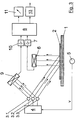
Die Meßvorrichtung gemäß Figur 2 unterscheidet sich von der in Figur 1 gezeigten
Variante dadurch, daß in dem Strahlengang zur Beaufschlagung des fotoelektrischen
Empfängers 9 mit dem entsprechend der Druckgeschwindigkeit v unterschiedlich
von der Lampe 3 abgegebenen Lichtes ein das Licht der Lampe 3 reflektierender
Weißstandard 12 (Absolutweiß) angeordnet ist. Auch in diesem Ausführungsbeispiel
werden die Ausgangssignale des fotoelektrischen Empfängers 9 über
eine Verstärkereinheit 10 der das Licht des fotoelektrischen Empfängers 6
verarbeitenden Auswerteeinheit 8 zugeleitet und in der obenstehend
beschriebenen Weise verarbeitet. Es folgt ebenfalls eine Ermittlung eines von den
unterschiedlichen spektralen Intensitätsverteilungen der Lampe 3 und somit von
der Druckgeschwindigkeit unabhängigen Meßwertes M (λ), welcher auf der
Anzeigeeinrichtung 11 darstellbar bzw. über den Transmitter 13 weiterleitbar ist.The measuring device according to FIG. 2 differs from that shown in FIG. 1
Variant in that in the beam path to act on the
Weiter obenstehend ist bereits angedeutet, daß es sich bei dem weiteren fotoelektrischen
Empfänger 9 zur Erfassung des direkt von der Lampe 3 abgegebenen
Lichtes um einen in gleicher Weise ausgebildeten Empfänger handeln kann, wie
dieser zur spektralen Aufteilung und fotoelektrischen Wandlung des von der Meßfläche
2 reflektrierten Lichtes Verwendung findet. Ebenfalls ist es dabei möglich,
den weiteren fotoelektrischen Empfänger 9 als ein das Licht der Lampe 3 in
beispielsweise zwei oder drei unterschiedlichen spektralen Bereichen selektiv
erfassendes Sensorsystem auszubilden und aufgrund der derartig erhaltenen
Meßwerte die spektrale Intensitätsverteilung des Lichtes unter Zugrundelegung
von Interpolationsalgorithmen zu ermitteln. Dies ist insbesondere bei dem ein
kontinuierliches Spektrum aufweisenden Licht von Glühlampen in einfacher Weise
möglich.It has already been indicated above that the further
Bei den in den Fig. 3 und 4 gezeigten Ausführungsvarianten weist die Beleuchtungseinrichtung insgesamt drei über die Steuerung 4 einzeln schaltbare Lampen 3.1, 3.2, 3.3 auf. Diese Lampen 3.1, 3.2, 3.3 sind dabei in der Leistung unterschiedlich und aufeinander abgestimmt. Vorzugsweise weist Lampe 3.2 die doppelte Leistung von Lampe 3.1 und Lampe 3.3 wiederum die doppelte Leistung von Lampe 3.2 auf. Durch einzelnes bzw. kombiniertes Schalten ein oder mehrerer der Lampen 3.1, 3.2, 3.3 ist es mit einer derartig ausgebildeten Beleuchtungseinrichtung möglich, einen Leistungsbereich, der dem siebenfachen der Leistung von Lampe 3.1 entspricht, abzudecken. Zusätzlich kann auch vorgesehen sein, wenigstens eine der Lampen 3.1, 3.2, 3.3 zumindest in einem Teil des Leistungsbereiches kontinuierlich bzw. in Leistungsstufen anzusteuern, so daß sich eine kontinuierliche bzw. quasikontinuierliche Anpassung der Beleuchtungsleistung entsprechend der jeweiligen Relativgeschwindigkeit v ergibt. In the embodiment variants shown in FIGS. 3 and 4, the lighting device has A total of three lamps that can be switched individually via the controller 3.1, 3.2, 3.3. These lamps 3.1, 3.2, 3.3 are in the power different and coordinated. Lamp 3.2 preferably has the double the power of lamp 3.1 and lamp 3.3 in turn double the power from lamp 3.2 on. By switching one or more individually or in combination the lamps 3.1, 3.2, 3.3 it is designed in such a way Lighting device possible, a power range that is seven times corresponds to the performance of lamp 3.1. In addition, too be provided, at least one of the lamps 3.1, 3.2, 3.3 at least in one To control part of the performance range continuously or in performance levels, see above that there is a continuous or quasi-continuous adaptation of the Illumination power corresponding to the respective relative speed v results.
- 11
- BedruckstoffSubstrate
- 22nd
- MeßfeldMeasuring field
- 3, 3.1,3.2, 3.33, 3.1,3.2, 3.3
- Lampelamp
- 44th
-
Steuerung (Lampen 3, 3.1, 3.2, 3.3)Control (
lamps 3, 3.1, 3.2, 3.3) - 55
- Signalgeber (Druckgeschwindigkeit v)Signal generator (printing speed v)
- 66
- fotoelektrischer Empfängerphotoelectric receiver
- 77
- VerstärkereinrichtungAmplifier device
- 88th
- AuswerteeinheitEvaluation unit
- 99
- fotoelektrischer Empfängerphotoelectric receiver
- 1010th
- VerstärkereinrichtungAmplifier device
- 1111
- AnzeigeeinrichtungDisplay device
- 1212th
- Weißstandard (weißer Diffusreflektor)White standard (white diffuse reflector)
- vv
- DruckgeschwindigkeitPrint speed
- UU
- Spannung (Lampe 3)Voltage (lamp 3)
- II.
- Strom (Lampe 3)Electricity (lamp 3)
Claims (15)
dadurch gekennzeichnet,
daß die Beleuchtungseinrichtung in Abhängigkeit der Relativgeschwindigkeit zwischen Meßfeld und Meßsystem angesteuert wird, daß bei der jeweiligen Relativgeschwindigkeit zwischen Meßfeldern und Meßsystem die spektrale Intensitätsverteilung der Lichtquelle der Beleuchtungseinrichtung erfaßt wird, und daß die jeweilig vorliegende spektrale Intensitätsverteilung des Lichtes der Lichtquelle der Beleuchtungseinrichtung bei der Verarbeitung der von den Meßfeldern reflektierten Strahlung zu Meßwerten mitberücksichtigt wird.Method for recording spectral remissions, in particular within a printing press, in which measuring fields moving at a speed relative to the measuring system are exposed to radiation of a stationary arrangement depending on the relative speed of radiation, and the radiation remitted by the measuring fields is further processed after photoelectric conversion to derive measured variables will,
characterized by
that the lighting device is controlled as a function of the relative speed between the measuring field and measuring system, that the spectral intensity distribution of the light source of the lighting device is detected at the respective relative speed between measuring fields and measuring system, and that the respective spectral intensity distribution of the light of the light source of the lighting device when processing the radiation reflected from the measuring fields is also taken into account for measured values.
dadurch gekennzeichnet,
daß die direkt von der Beleuchtungseinrichtung abgegebene Strahlung zur Feststellung der spektralen Intensitätsverteilung der Lichtquelle der Beleuchtungseinrichtung des Meßsystems verwendet wird.Method according to claim 1,
characterized by
that the radiation emitted directly by the lighting device is used to determine the spectral intensity distribution of the light source of the lighting device of the measuring system.
dadurch gekennzeichnet,
daß die an einem Weißstandard reflektierte Strahlung der Beleuchtungseinrichtung zur Feststellung der spektralen Intensitätsverteilung der Beleuchtungseinrichtung des Meßsystems verwendet wird. Method according to claim 1,
characterized by
that the radiation of the illuminating device reflected on a white standard is used to determine the spectral intensity distribution of the illuminating device of the measuring system.
dadurch gekennzeichnet,
daß zur Feststellung der spektralen Intensitätsverteilung der Strahlung der Beleuchtungseinrichtung eine Erfassung der Intensitäten in wenigstens zwei spektralen Bereichen erfolgt.Method according to one of the preceding claims,
characterized by
that to determine the spectral intensity distribution of the radiation from the lighting device, the intensities are detected in at least two spectral ranges.
dadurch gekennzeichnet,
daß zur Feststellung der spektralen Intensitätsverteilung der Strahlung der Beleuchtungseinrichtung eine Interpolation über die wenigstens zwei erfaßten spektralen Intensitäten als Stützstellen erfolgt.Method according to claim 4,
characterized by
that to determine the spectral intensity distribution of the radiation from the illumination device, an interpolation takes place over the at least two detected spectral intensities as support points.
dadurch gekennzeichnet,
daß bei mehreren Lichtquellen der Beleuchtungseinrichtung diese in Abhängigkeit der Relativgeschwindigkeit v einzeln und/oder gruppenweise geschaltet werden.Method according to one of the preceding claims,
characterized by
that in the case of several light sources of the lighting device, these are switched individually and / or in groups depending on the relative speed v.
dadurch gekennzeichnet,
daß wenigstens eine als Glühlampe ausgebildete Lichtquelle der Beleuchtungseinrichtung in Abhängigkeit der Relativgeschwindigkeit v zwischen Meßfeldern und Meßsystem mit unterschiedlicher Betriebsspannung / unterschiedlichem Betriebsstrom angesteuert wird. Method according to one of the preceding claims,
characterized by
that at least one light source, designed as an incandescent lamp, of the lighting device is driven with different operating voltage / different operating current depending on the relative speed v between measuring fields and measuring system.
dadurch gekennzeichnet,
daß die Beleuchtungseinrichtung eine Steuerung (4) zur Erzeugung geschwindigkeitsabhängiger Strahlungsstärken der Lichtquelle (3) aufweist, daß der Beleuchtungseinrichtung ein zusätzlicher Meßkanal (9, 10; 12) zur Erfassung der spektralen Intensitätsverteilung der Strahlung der Lichtquelle (3) zugeordnet ist, und daß durch die Auswerteeinheit (8) eine Verarbeitung der von den Meßfeldern (2) reflektierten Strahlung in Verbindung mit der spektralen Intensitätsverteilung der Strahlung der Lichtquelle (3) zur Ermittlung von Meßwerten erfolgt.Device for carrying out the method according to one of the preceding claims, with an illuminating device for irradiating measuring fields moving at a relative speed with respect to the measuring device on a printing material, a device within the illuminating device for changing the irradiation intensity of the measuring fields as a function of speed, and at least one measuring channel for photoelectric conversion of the radiation reflected from the measuring fields and downstream evaluation unit for determining measured values,
characterized by
that the lighting device has a control (4) for generating speed-dependent radiation levels of the light source (3), that the lighting device is assigned an additional measuring channel (9, 10; 12) for detecting the spectral intensity distribution of the radiation from the light source (3), and that the evaluation unit (8) processes the radiation reflected by the measuring fields (2) in conjunction with the spectral intensity distribution of the radiation from the light source (3) to determine measured values.
dadurch gekennzeichnet,
daß durch den der Lichtquelle (3) zugeordneten Meßkanal (9, 10) die direkt von der Lichtquelle (3) abgegebene Strahlung erfassbar ist.Device according to claim 8,
characterized by
that the radiation emitted directly by the light source (3) can be detected by the measuring channel (9, 10) assigned to the light source (3).
dadurch gekennzeichnet,
daß in dem der Lichtquelle (3) zugeordneten Meßkanal (9, 10) ein die Strahlung der Lichtquelle (3) reflektierender Weißstandard (12) angeordnet ist. Device according to claim 8,
characterized by
that a white standard (12) reflecting the radiation from the light source (3) is arranged in the measuring channel (9, 10) assigned to the light source (3).
dadurch gekennzeichnet,
daß der fotoelektrische Wandler (9) in dem der Lichtquelle (3) zugeordneten Meßkanal (9, 10) und der fotoelektrische Wandler (6) in dem dem Meßfeld (2) zugeordneten Meßkanal (6, 7) als gleichartige Meßsysteme ausgebildet sind.Device according to claim 8, 9 or 10,
characterized by
that the photoelectric converter (9) in the measuring channel (9, 10) assigned to the light source (3) and the photoelectric converter (6) in the measuring channel (6) assigned to the measuring field (6, 7) are designed as similar measuring systems.
dadurch gekennzeichnet,
daß durch den fotoelektrischen Wandler (9) in dem der Lichtquelle (3) zugeordneten Meßkanal (9, 10) die Strahlung der Lichtquelle (3) in wenigstens zwei spektralen Bereichen erfaßbar ist.Device according to claim 8, 9 or 10,
characterized by
that the radiation from the light source (3) can be detected in at least two spectral ranges by the photoelectric converter (9) in the measuring channel (9, 10) assigned to the light source (3).
dadurch gekennzeichnet,
daß durch die Auswerteeinheit (8) eine Interpolation über die erfaßten spektralen Intensitäten als Stützstellen erfolgt.Device according to claim 12,
characterized by
that the evaluation unit (8) interpolates over the detected spectral intensities as support points.
dadurch gekennzeichnet,
daß die Lichtquelle (3) der Beleuchtungseinrichtung als wenigstens eine Glühlampe ausgebildet ist, welche über die Steuerung (4) in Abhängigkeit der Relativgeschwindigkeit (v) zwischen Meßfeld (2) und Meßeinrichtung (3 - 12) mit unterschiedlichen Betriebsspannungen/Strömen (U/I) betreibbar ist. Device according to one or more of claims 8-13,
characterized by
that the light source (3) of the lighting device is designed as at least one incandescent lamp, which with the control (4) depending on the relative speed (v) between the measuring field (2) and measuring device (3 - 12) with different operating voltages / currents (U / I ) is operable.
dadurch gekennzeichnet,
daß die Beleuchtungseinrichtung mehrere insbesondere als Glühlampen ausgebildeten Lichtquellen (3; 3.1, 3.2, 3.3) aufweist, welche über die Steuerung (4) in Abhängigkeit der Relativgeschwindigkeit (v) zwischen Meßfeld (2) und Meßeinrichtung (3 - 12) einzeln und/oder gruppenweise schaltbar sind.Device according to one or more of claims 8-14,
characterized by
that the lighting device has a plurality of light sources (3; 3.1, 3.2, 3.3), in particular in the form of incandescent lamps, which individually and / or via the controller (4) as a function of the relative speed (v) between the measuring field (2) and the measuring device (3 - 12) are switchable in groups.
Applications Claiming Priority (2)
| Application Number | Priority Date | Filing Date | Title |
|---|---|---|---|
| DE19628303A DE19628303C2 (en) | 1996-07-13 | 1996-07-13 | Method and device for recording spectral remissions |
| DE19628303 | 1996-07-13 |
Publications (3)
| Publication Number | Publication Date |
|---|---|
| EP0818675A2 true EP0818675A2 (en) | 1998-01-14 |
| EP0818675A3 EP0818675A3 (en) | 1998-04-15 |
| EP0818675B1 EP0818675B1 (en) | 2003-04-09 |
Family
ID=7799751
Family Applications (1)
| Application Number | Title | Priority Date | Filing Date |
|---|---|---|---|
| EP97110961A Expired - Lifetime EP0818675B1 (en) | 1996-07-13 | 1997-07-02 | Method and device for spectral remission measurement |
Country Status (5)
| Country | Link |
|---|---|
| US (1) | US5973789A (en) |
| EP (1) | EP0818675B1 (en) |
| JP (1) | JPH1073485A (en) |
| AT (1) | ATE237130T1 (en) |
| DE (2) | DE19628303C2 (en) |
Cited By (3)
| Publication number | Priority date | Publication date | Assignee | Title |
|---|---|---|---|---|
| DE19920184A1 (en) * | 1999-05-03 | 2000-11-30 | Optosens Optische Spektroskopi | Simultaneous detection of diffuse, specular reflections from specimens involves coupling radiation from receiver plane into space between receiver, optical planes, using two receivers |
| WO2001065218A1 (en) * | 2000-03-02 | 2001-09-07 | Ndc Infrared Engineering Limited | Electromagnetic detection apparatus |
| WO2015036565A3 (en) * | 2013-09-12 | 2015-06-11 | Windmöller & Hölscher Kg | Sensor with variable light beam for optically detecting marks on a moving material web |
Families Citing this family (7)
| Publication number | Priority date | Publication date | Assignee | Title |
|---|---|---|---|---|
| DE19837084B4 (en) * | 1998-08-17 | 2009-10-08 | Volkswagen Ag | Method for optically detecting welds between a wheel disc and a wheel rim of a motor vehicle wheel |
| TW430738B (en) * | 2000-05-22 | 2001-04-21 | Acer Peripherals Inc | A detection device to detect the light emitted from a planar light source |
| FR2827043B1 (en) * | 2001-07-05 | 2004-02-27 | I2S | METHOD FOR DIGITIZING A HIGH SPEED SCROLLING SURFACE |
| US7251065B2 (en) * | 2002-01-31 | 2007-07-31 | Eastman Kodak Company | Image color balance for scanners using an illumination spectral sensor |
| DE102004064309B3 (en) | 2004-05-03 | 2022-02-10 | Heidelberger Druckmaschinen Ag | Inline measurement and control for printing presses |
| FR2881373B1 (en) * | 2005-02-01 | 2008-08-22 | Centre Nat Rech Scient | DETECTION SYSTEM FOR OFFSET PRINTING AND MACHINE USING THE SAME |
| JP2020036148A (en) * | 2018-08-29 | 2020-03-05 | 京セラドキュメントソリューションズ株式会社 | Image reading device and image forming apparatus |
Citations (3)
| Publication number | Priority date | Publication date | Assignee | Title |
|---|---|---|---|---|
| EP0378283A2 (en) * | 1989-01-12 | 1990-07-18 | Komori Corporation | Quality inspection device for printed matter and method thereof |
| US5168155A (en) * | 1989-12-28 | 1992-12-01 | Minolta Camera Co., Ltd. | Color measuring apparatus with flash lamp color temperature measurement |
| WO1995000335A1 (en) * | 1993-06-25 | 1995-01-05 | Heidelberger Druckmaschinen Ag | Device for the parallel image inspection and colour control of a printed product |
Family Cites Families (5)
| Publication number | Priority date | Publication date | Assignee | Title |
|---|---|---|---|---|
| US3892492A (en) * | 1972-10-16 | 1975-07-01 | Loepfe Ag Geb | Optoelectrical apparatus with directional light sources for detecting reflection behaviour of an object |
| DD219730A1 (en) * | 1983-11-14 | 1985-03-13 | Polygraph Leipzig | METHOD OF MEASURING COLOR DENSITY ON A RUNNING PRINTING MACHINE |
| JPS62139543A (en) * | 1985-12-13 | 1987-06-23 | Minolta Camera Co Ltd | Copying machine |
| EP0432302B1 (en) * | 1989-12-14 | 1994-03-02 | Victor Company Of Japan, Limited | Electrophotography system |
| DE4013422C2 (en) * | 1990-04-26 | 2000-02-03 | Roland Man Druckmasch | Illumination device for a three-area color measuring device |
-
1996
- 1996-07-13 DE DE19628303A patent/DE19628303C2/en not_active Expired - Fee Related
-
1997
- 1997-07-02 AT AT97110961T patent/ATE237130T1/en not_active IP Right Cessation
- 1997-07-02 EP EP97110961A patent/EP0818675B1/en not_active Expired - Lifetime
- 1997-07-02 DE DE59709746T patent/DE59709746D1/en not_active Expired - Fee Related
- 1997-07-11 US US08/891,375 patent/US5973789A/en not_active Expired - Fee Related
- 1997-07-14 JP JP9187947A patent/JPH1073485A/en active Pending
Patent Citations (3)
| Publication number | Priority date | Publication date | Assignee | Title |
|---|---|---|---|---|
| EP0378283A2 (en) * | 1989-01-12 | 1990-07-18 | Komori Corporation | Quality inspection device for printed matter and method thereof |
| US5168155A (en) * | 1989-12-28 | 1992-12-01 | Minolta Camera Co., Ltd. | Color measuring apparatus with flash lamp color temperature measurement |
| WO1995000335A1 (en) * | 1993-06-25 | 1995-01-05 | Heidelberger Druckmaschinen Ag | Device for the parallel image inspection and colour control of a printed product |
Cited By (5)
| Publication number | Priority date | Publication date | Assignee | Title |
|---|---|---|---|---|
| DE19920184A1 (en) * | 1999-05-03 | 2000-11-30 | Optosens Optische Spektroskopi | Simultaneous detection of diffuse, specular reflections from specimens involves coupling radiation from receiver plane into space between receiver, optical planes, using two receivers |
| DE19920184C2 (en) * | 1999-05-03 | 2001-06-07 | Optosens Optische Spektroskopi | Methods for the simultaneous detection of diffuse and specular reflection of samples, in particular opaque samples, and reflectance measuring probe |
| WO2001065218A1 (en) * | 2000-03-02 | 2001-09-07 | Ndc Infrared Engineering Limited | Electromagnetic detection apparatus |
| US6875985B2 (en) | 2000-03-02 | 2005-04-05 | Ndc Infrared Engineering Limited | Electomagnetic detection apparatus |
| WO2015036565A3 (en) * | 2013-09-12 | 2015-06-11 | Windmöller & Hölscher Kg | Sensor with variable light beam for optically detecting marks on a moving material web |
Also Published As
| Publication number | Publication date |
|---|---|
| DE19628303C2 (en) | 1998-05-07 |
| EP0818675A3 (en) | 1998-04-15 |
| EP0818675B1 (en) | 2003-04-09 |
| DE59709746D1 (en) | 2003-05-15 |
| ATE237130T1 (en) | 2003-04-15 |
| DE19628303A1 (en) | 1998-01-22 |
| US5973789A (en) | 1999-10-26 |
| JPH1073485A (en) | 1998-03-17 |
Similar Documents
| Publication | Publication Date | Title |
|---|---|---|
| DE19617009C2 (en) | Photoelectric measuring device | |
| EP1694049B1 (en) | Colour measuring device and corresponding measuring head | |
| EP0824736B1 (en) | Device and process for checking sheet articles such as bank notes or securities | |
| EP1805979B1 (en) | Method for correcting measured image values | |
| EP0884181B1 (en) | Process for regulating operations carried out by a printing machine | |
| EP0818675B1 (en) | Method and device for spectral remission measurement | |
| EP1470918A2 (en) | System and method for measuring color on a printing press | |
| EP2003431B1 (en) | Method for measuring the colour of printed samples with brighteners | |
| DE4109744A1 (en) | METHOD FOR DETERMINING THE SURFACE COVERAGE OF A TEMPLATE, ESPECIALLY A PRINT PLATE, AND APPARATUS FOR IMPLEMENTING THE METHOD | |
| DE102004058408B4 (en) | Device for determining surface properties | |
| DE102005024271B4 (en) | Grating spectrometer system and method for measured value acquisition | |
| US6535279B1 (en) | Measuring device for the quality control of printed products | |
| EP2034286B1 (en) | Method of controlling printing process using a spectral measuring system comprising spatial light modulator | |
| EP0886772B1 (en) | Analysis system | |
| DE10356729B4 (en) | color sensor | |
| DE4439533C2 (en) | Device and method for colorimetric detection of color control fields in the color calibration of the colors output by electronic image processing systems | |
| DE19927452C2 (en) | Device for measuring moisture and reflectivity of surfaces | |
| DE19542239C2 (en) | Method and device for the area-by-area measurement of the permeability of a photographic color copy original | |
| JP2005037294A (en) | Quality evaluation apparatus of fruit vegetables | |
| JP2004157025A (en) | Multi-sensor head and print quality controlling apparatus using the same | |
| DE2130165C3 (en) | Method and device for determining the ratio of the unprinted to the printed area of an original | |
| WO1999054713A2 (en) | Device and method for detecting a shift in a surface plasmon resonance | |
| WO2009019120A1 (en) | Device and method for metrologically capturing a color of an object | |
| DE3544422A1 (en) | Device for measuring layer thickness in printing machines | |
| JPH08132595A (en) | Ink supply volume controlling apparatus and method for multi-color printer |
Legal Events
| Date | Code | Title | Description |
|---|---|---|---|
| PUAI | Public reference made under article 153(3) epc to a published international application that has entered the european phase |
Free format text: ORIGINAL CODE: 0009012 |
|
| AK | Designated contracting states |
Kind code of ref document: A2 Designated state(s): AT CH DE FR GB IT LI NL SE |
|
| PUAL | Search report despatched |
Free format text: ORIGINAL CODE: 0009013 |
|
| AK | Designated contracting states |
Kind code of ref document: A3 Designated state(s): AT BE CH DE DK ES FI FR GB GR IE IT LI LU MC NL PT SE |
|
| 17P | Request for examination filed |
Effective date: 19980325 |
|
| AKX | Designation fees paid |
Free format text: AT CH DE FR GB IT LI NL SE |
|
| RBV | Designated contracting states (corrected) |
Designated state(s): AT CH DE FR GB IT LI NL SE |
|
| 17Q | First examination report despatched |
Effective date: 20011022 |
|
| GRAH | Despatch of communication of intention to grant a patent |
Free format text: ORIGINAL CODE: EPIDOS IGRA |
|
| GRAH | Despatch of communication of intention to grant a patent |
Free format text: ORIGINAL CODE: EPIDOS IGRA |
|
| GRAA | (expected) grant |
Free format text: ORIGINAL CODE: 0009210 |
|
| AK | Designated contracting states |
Designated state(s): AT CH DE FR GB IT LI NL SE |
|
| PG25 | Lapsed in a contracting state [announced via postgrant information from national office to epo] |
Ref country code: NL Free format text: LAPSE BECAUSE OF FAILURE TO SUBMIT A TRANSLATION OF THE DESCRIPTION OR TO PAY THE FEE WITHIN THE PRESCRIBED TIME-LIMIT Effective date: 20030409 Ref country code: IT Free format text: LAPSE BECAUSE OF FAILURE TO SUBMIT A TRANSLATION OF THE DESCRIPTION OR TO PAY THE FEE WITHIN THE PRESCRIBED TIME-LIMIT;WARNING: LAPSES OF ITALIAN PATENTS WITH EFFECTIVE DATE BEFORE 2007 MAY HAVE OCCURRED AT ANY TIME BEFORE 2007. THE CORRECT EFFECTIVE DATE MAY BE DIFFERENT FROM THE ONE RECORDED. Effective date: 20030409 |
|
| REG | Reference to a national code |
Ref country code: GB Ref legal event code: FG4D Free format text: NOT ENGLISH |
|
| REG | Reference to a national code |
Ref country code: CH Ref legal event code: EP |
|
| GBT | Gb: translation of ep patent filed (gb section 77(6)(a)/1977) |
Effective date: 20030409 |
|
| REG | Reference to a national code |
Ref country code: CH Ref legal event code: NV Representative=s name: E. BLUM & CO. PATENTANWAELTE |
|
| PG25 | Lapsed in a contracting state [announced via postgrant information from national office to epo] |
Ref country code: SE Free format text: LAPSE BECAUSE OF FAILURE TO SUBMIT A TRANSLATION OF THE DESCRIPTION OR TO PAY THE FEE WITHIN THE PRESCRIBED TIME-LIMIT Effective date: 20030709 |
|
| NLV1 | Nl: lapsed or annulled due to failure to fulfill the requirements of art. 29p and 29m of the patents act | ||
| ET | Fr: translation filed | ||
| PLBE | No opposition filed within time limit |
Free format text: ORIGINAL CODE: 0009261 |
|
| STAA | Information on the status of an ep patent application or granted ep patent |
Free format text: STATUS: NO OPPOSITION FILED WITHIN TIME LIMIT |
|
| 26N | No opposition filed |
Effective date: 20040112 |
|
| PGFP | Annual fee paid to national office [announced via postgrant information from national office to epo] |
Ref country code: GB Payment date: 20050621 Year of fee payment: 9 |
|
| PGFP | Annual fee paid to national office [announced via postgrant information from national office to epo] |
Ref country code: AT Payment date: 20050628 Year of fee payment: 9 |
|
| PGFP | Annual fee paid to national office [announced via postgrant information from national office to epo] |
Ref country code: FR Payment date: 20050712 Year of fee payment: 9 |
|
| PG25 | Lapsed in a contracting state [announced via postgrant information from national office to epo] |
Ref country code: GB Free format text: LAPSE BECAUSE OF NON-PAYMENT OF DUE FEES Effective date: 20060702 Ref country code: AT Free format text: LAPSE BECAUSE OF NON-PAYMENT OF DUE FEES Effective date: 20060702 |
|
| GBPC | Gb: european patent ceased through non-payment of renewal fee |
Effective date: 20060702 |
|
| REG | Reference to a national code |
Ref country code: FR Ref legal event code: ST Effective date: 20070330 |
|
| REG | Reference to a national code |
Ref country code: CH Ref legal event code: PFA Owner name: MAN ROLAND DRUCKMASCHINEN AG Free format text: MAN ROLAND DRUCKMASCHINEN AG#MUEHLHEIMER STRASSE 341#63075 OFFENBACH (DE) -TRANSFER TO- MAN ROLAND DRUCKMASCHINEN AG#MUEHLHEIMER STRASSE 341#63075 OFFENBACH (DE) |
|
| PG25 | Lapsed in a contracting state [announced via postgrant information from national office to epo] |
Ref country code: FR Free format text: LAPSE BECAUSE OF NON-PAYMENT OF DUE FEES Effective date: 20060731 |
|
| REG | Reference to a national code |
Ref country code: CH Ref legal event code: PFA Owner name: MANROLAND AG Free format text: MAN ROLAND DRUCKMASCHINEN AG#MUEHLHEIMER STRASSE 341#63075 OFFENBACH (DE) -TRANSFER TO- MANROLAND AG#MUEHLHEIMER STRASSE 341#63075 OFFENBACH (DE) |
|
| PGFP | Annual fee paid to national office [announced via postgrant information from national office to epo] |
Ref country code: DE Payment date: 20090722 Year of fee payment: 13 Ref country code: CH Payment date: 20090715 Year of fee payment: 13 |
|
| REG | Reference to a national code |
Ref country code: CH Ref legal event code: PL |
|
| PG25 | Lapsed in a contracting state [announced via postgrant information from national office to epo] |
Ref country code: CH Free format text: LAPSE BECAUSE OF NON-PAYMENT OF DUE FEES Effective date: 20100731 Ref country code: DE Free format text: LAPSE BECAUSE OF NON-PAYMENT OF DUE FEES Effective date: 20110201 Ref country code: LI Free format text: LAPSE BECAUSE OF NON-PAYMENT OF DUE FEES Effective date: 20100731 |
|
| REG | Reference to a national code |
Ref country code: DE Ref legal event code: R119 Ref document number: 59709746 Country of ref document: DE Effective date: 20110201 |