EP0818669A1 - Weighing machine - Google Patents
Weighing machine Download PDFInfo
- Publication number
- EP0818669A1 EP0818669A1 EP97202733A EP97202733A EP0818669A1 EP 0818669 A1 EP0818669 A1 EP 0818669A1 EP 97202733 A EP97202733 A EP 97202733A EP 97202733 A EP97202733 A EP 97202733A EP 0818669 A1 EP0818669 A1 EP 0818669A1
- Authority
- EP
- European Patent Office
- Prior art keywords
- vibration
- floor
- weight
- detecting
- signal
- Prior art date
- Legal status (The legal status is an assumption and is not a legal conclusion. Google has not performed a legal analysis and makes no representation as to the accuracy of the status listed.)
- Granted
Links
Images


Classifications
-
- G—PHYSICS
- G01—MEASURING; TESTING
- G01G—WEIGHING
- G01G23/00—Auxiliary devices for weighing apparatus
- G01G23/06—Means for damping oscillations, e.g. of weigh beams
- G01G23/10—Means for damping oscillations, e.g. of weigh beams by electric or magnetic means
-
- G—PHYSICS
- G01—MEASURING; TESTING
- G01G—WEIGHING
- G01G19/00—Weighing apparatus or methods adapted for special purposes not provided for in the preceding groups
- G01G19/387—Weighing apparatus or methods adapted for special purposes not provided for in the preceding groups for combinatorial weighing, i.e. selecting a combination of articles whose total weight or number is closest to a desired value
- G01G19/393—Weighing apparatus or methods adapted for special purposes not provided for in the preceding groups for combinatorial weighing, i.e. selecting a combination of articles whose total weight or number is closest to a desired value using two or more weighing units
-
- G—PHYSICS
- G01—MEASURING; TESTING
- G01G—WEIGHING
- G01G3/00—Weighing apparatus characterised by the use of elastically-deformable members, e.g. spring balances
- G01G3/12—Weighing apparatus characterised by the use of elastically-deformable members, e.g. spring balances wherein the weighing element is in the form of a solid body stressed by pressure or tension during weighing
- G01G3/14—Weighing apparatus characterised by the use of elastically-deformable members, e.g. spring balances wherein the weighing element is in the form of a solid body stressed by pressure or tension during weighing measuring variations of electrical resistance
- G01G3/1414—Arrangements for correcting or for compensating for unwanted effects
-
- G—PHYSICS
- G01—MEASURING; TESTING
- G01G—WEIGHING
- G01G3/00—Weighing apparatus characterised by the use of elastically-deformable members, e.g. spring balances
- G01G3/12—Weighing apparatus characterised by the use of elastically-deformable members, e.g. spring balances wherein the weighing element is in the form of a solid body stressed by pressure or tension during weighing
- G01G3/14—Weighing apparatus characterised by the use of elastically-deformable members, e.g. spring balances wherein the weighing element is in the form of a solid body stressed by pressure or tension during weighing measuring variations of electrical resistance
- G01G3/142—Circuits specially adapted therefor
- G01G3/147—Circuits specially adapted therefor involving digital counting
Definitions
- This invention relates to weighing machines using load sensors such as load cells set on a floor to measure the weight of articles such as food items and industrial machine parts. More particularly, the invention relates to means for correcting the effects of lower-frequency floor vibrations on weight signals generated and processed by such a weighing machine.
- Patent 4,624,331 disclosed a weighing machine having not only a scale cell for measuring the weight of an object and outputting a weight signal indicative of the measured weight, but also a dummy cell set on the same floor as the scale cell such that the effects of the floor vibrations can be eliminated from the weight signal by inverting the dummy signal outputted from the dummy cell and adding it to the weight signal from the scale cell. In this manner, the cutoff frequency of the filter can be set higher, and hence the weighing speed is not reduced.
- the scale cell and the dummy cell must be set close to each other because the floor at the positions of the two cells is assumed to be vibrating under the same conditions. If the conditions of vibrations are different at the positions of the cells, corrections cannot be effected accurately by subtracting the dummy signal of the dummy cell from the weight signal. There may even be situations where the error becomes magnified by the "correction". In short, the choice of the position for installing the dummy cell becomes extremely limited, and the degree of freedom in designing the weighing machine is reduced. If there is not much free space in the neighborhood of the scale cell, in particular, it is extremely difficult to find an adequate place for installing the dummy cell for this purpose.
- Japanese Patent Publication Tokkai 64-32122 disclosed a combinational weighing machine adapted to determine the vibration characteristics of the floor from the average of weight signals outputted from those load sensors not selected in the preceding cycle of combinational calculations and to thereby correct the signals outputted from the selected load sensors.
- This correction routine is based, however, on the assumption that the floor vibrations are identical at the positions of the plurality of load sensors. If this assumption does not hold, the effects of floor vibrations cannot be eliminated accurately by subtracting such an average value.
- the weight sensitivity Since the load on the scale cell may be very different from the load on the vibration-detecting cell, however, prior art correction methods ignoring the sensitivity differences due to the difference in load (hereinafter referred to as the weight sensitivity) cannot be accurate. Accuracy in measurements is believed to decline as the weight of the object being weighed increases.
- a weighing machine comprises a scale cell for weighing an object and outputting a weight signal indicative of measured weight value of said object; a vibration-detecting cell set on a same floor as said scale cell for outputting a floor vibration signal indicative of the vibration of said floor; correcting means for correcting said weight signal on the basis of said floor vibration signal outputted from said vibration-detecting cell and thereby generating vibration corrected signal indicative of corrected weight value of said object not containing effects of said vibration of said floor; and correction control means for detecting vibration components of said floor and stopping operations of said correcting means by comparing said vibration components with a reference value.
- the invention provides a weighing machine capable of accurately removing the effects of floor vibrations from weight signals to thereby yield highly accurate results of weighing.
- the invention provides means for accurately and quickly removing the effects of floor vibrations on weight values obtained by a weighing machine independent of the size of the weight of the object being weighed.
- Weighing machines in accordance with the invention can be made compact and to cost less.
- the weighing machine does not require any extra dummy or vibration-detecting cells or amplifiers therefor but is still capable of accurately removing the effects of floor vibrations from weight signals even in situations where the conditions of vibrations are different at the positions of its load sensors.
- the invention can also provide a weighing machine capable of providing an accurate weight value independent of whether the amplitude of floor vibrations is large or small.
- the weighing machine may preferably also comprise a cell sensitivity setting means for setting cell sensitivity ratio at least between the scale cells and the dummy cells (and possibly also among the scale cells and among the dummy cells) on the basis of the loads on the dummy cells and those of the scale cells when not carrying any object to be weighed and the spring constants of the scale and dummy cells, and also a cell sensitivity correcting means for generating cell sensitivity corrected signals to correct at least a weight signal or a dummy signal by using the aforementioned cell sensitivity ratio.
- a cell sensitivity setting means for setting cell sensitivity ratio at least between the scale cells and the dummy cells (and possibly also among the scale cells and among the dummy cells) on the basis of the loads on the dummy cells and those of the scale cells when not carrying any object to be weighed and the spring constants of the scale and dummy cells
- a cell sensitivity correcting means for generating cell sensitivity corrected signals to correct at least a weight signal or a dummy signal by using the
- such a weighing machine may additionally comprise a weight sensitivity calculating means for calculating weight sensitivity ratio at least between the scale cells and the dummy cells (and possibly also among the scale cells) corresponding to the weight of the object to be weighed and a weight sensitivity correcting means for generating weight sensitivity corrected signals by using the aforementioned weight sensitivity ratio to correct at least either the weight or dummy signals.
- the vibration modes of the floor at the positions of the scale cells are detected by the dummy cells, and the vertical displacements of the floor at these positions are calculated and used for correcting the weight signals. Accordingly, the weight signals can be accurately corrected even if the vibrating conditions of the floor are different at the positions of the scale and dummy cells.
- the dummy cells do not have to be necessarily installed close to the scale cells, and hence the degree of structural freedom of the weighing machine is improved.
- the cell sensitivity correcting means generation of errors due to differences in sensitivity of the cells can be prevented and the accuracy in correction can be improved.
- the weight sensitivity calculating means generation of errors due to changes in sensitivity due to the weight of the object being weighed can also be prevented and the accuracy in correction can be further improved.
- the weighing machine may carry out cycles of combinational calculations to thereby select a combination of said weight signals satisfying a preset criterion, and discharging objects weighed by those of said load sensors which outputted said selected combination of weight signals, wherein the dummy cells are defined by the floor vibration calculating means as those scale cells whose weight signals not selected in the preceding cycle of the combinational calculations.
- This weighing machine may preferably also comprise a cell sensitivity correcting means for generating cell sensitivity corrected signals and, more preferably, also a weight sensitivity calculating means for generating weight sensitivity corrected signals.
- the main advantage of this weighing machine is that neither dummy cells structured identically to the scale cells nor amplifiers therefore are needed for eliminating the effects of floor vibrations and hence that the cost of the weighing machine can be reduced.
- the dummy signals are used to calculate the vertical displacements of the floor as explained above regarding a weighing machine according to the first aspect of the invention.
- Cell sensitivity correcting means and weight sensitivity calculating means similarly contribute to further improving the accuracy in the corrections.
- the floor vibration correcting means may include:
- the floor vibration correcting means serves to eliminate the effects of floor vibrations obtained from the vibration-detecting cell from the weight value of the object being weighed contained in the weight signal when the weight of this object has been added, and this floor vibration correcting means comprises a cell sensitivity setting means for setting the sensitivity ratio K between the scale cell when the weight of the object is not added and the vibration-detecting cell, an initial load setting means for setting an initial load value M for the scale cell when the weight of the object is not applied, and a weight calculating means for calculating the weight m of the object by a formula rather than by carrying out a time-consuming feedback process.
- a weighing machine may also be adapted to provide accurate weight values independent of whether the amplitude of floor vibrations is large or small.
- Such a weighing machine may comprise, in addition to scale cells and dummy cells (the roles of which may be played by those of the scale cells not selected in the previous cycle of combinational calculation) as described above, not only a correcting circuit for correcting weight signals outputted from the scale cells on the basis of floor vibration signals outputted from the dummy cells and thereby generating vibration corrected signal indicative of corrected weight values not containing effects of the floor vibrations, but also correction control means for detecting amplitudes of the floor vibrations and stopping the operation of the correcting circuit if the detected amplitudes are not large enough, as compared to present reference values.
- FIG. 1 represents a signal processing system according to a first comparative example of a combinational weighing machine
- load sensors 1 1 -1 m each comprising a weigh hopper 2 1 -2 m and a scale cell 3 1 -3 m such that objects X 1 -X m placed in the weigh hoppers 2 1 -2 m , are weighed respectively by the corresponding ones of the scale cells 3 1 -3 m and analog weight signals W 1 -W m representing their weights are outputted.
- dummy cells 4 1 -4 n installed through frames FR on the same floor F as the scale cells 3 1 -3 m , being adapted to output analog dummy signals D 1 -D n caused by the floor vibrations.
- the dummy cells 4 1 -4 n may be installed either on the frames for the weighing machine or on separately prepared frames.
- the analog weight signals W 1 -W m outputted from the load sensors 1 1 -1 m are amplified by amplifiers 6 1 -6 m and inputted into a multiplex 5.
- the dummy signals D 1 -D n from the dummy cells 4 1 -4 n are also amplified by amplifiers 7 1 -7 n and inputted into the same multiplexer 5.
- the signals W 1 -W m and D 1 -D n selectively outputted from the multiplexer 5 in response to a switch signal c from a CPU 9, are converted into digital signals by an analog-to-digital (A/D) converter 8.
- the CPU 9 which also serves as a calculating means, carries out vibration corrections and combinational calculations by using the digital weight and dummy signals W 1 -W m , and D 1 -D n received through the A/D converter 8 and outputs open signals OS for selectively opening a combination of weigh hoppers 2 1 -2 m which satisfies a preset criterion (such as having the total weight closest to a preset target weight value).
- a preset criterion such as having the total weight closest to a preset target weight value.
- the CPO 9 contains digital filters 10 1 -10 m and 11 1 -11 n .
- the weight and dummy signals W 1 -W m , and D 1 -D n which are selectively outputted from the multiplexer 5 and converted into digital signals by the A/D converter 8, are passed through a switching circuit 12 and corresponding one of the digital filters 10 1 -10 m and 11 1 -11 n such that their components with relatively high frequencies, generated principally when objects X to be weighed are put inside the weigh hoppers 2 1 -2 m , are eliminated.
- the CPU 9 also includes a floor vibration calculating means 13 for detecting the vibration mode of the floor on the basis of the digital dummy signals D 1 -D n received through the filters 11 1 -11 n , calculating therefrom the vertical displacements of the floor at the positions of the scale cells 1 1 -1 m and outputting displacement signals S 1 -S m indicative of these calculated vertical displacements of the floor.
- These displacement signals S 1 -S m are respectively received by floor vibration correcting means 14 1 -14 m for respectively correcting the digital weight signals W 1 -W 2 received respectively through the filters 10 1 -10 m .
- the effects of the vibrations represented by the displacement signals S 1 -S m are subtracted from the measured weight values represented by the weight signals W 1 -W m to generate and output vibration corrected weight signals BS 1 -BS m .
- Low frequency components of the floor vibrations are thus corrected, this makes it possible to set the cutoff frequencies of the filters 10 1 -10 m relatively high and to allow speedy weighing operations.
- the vibration corrected weight signals BS 1 -BS m thus outputted are received by a combination calculating means 20 for selecting a particular combination thereof in view of a preset criterion such that the total weight represented by such combination be the closest to a preset target weight value, and outputting an selection signal (or open signal) OS to open those of the weigh hoppers 2 1 -2 m corresponding to the selected combination. Since the correction operations are carried out digitally according to the illustrated example, more accurate corrections are possible than if they are done by using analog circuits along which there tend to be individual fluctuations.
- a method such as the one described above, of detecting the vibration modes of a floor and canceling the vibration components of scale cells at arbitrary positions thereon is referred to as a multi-point AFV (anti-floor vibration) process.
- the scale cells are distributed two-dimensionally (say, on a horizontal plane)
- floor vibrations are detected by dummy cells at three or more positions on the plane not in collinear relationship
- the vibration modes of the floor are detected from the vibrations detected thereby, and the vibration components of the floor at arbitrary positions of the scale cells are obtained therefrom and subtracted from the weight values being outputted from the scale cells.
- FIG. 3 shows the structure of a load cell 3(4) used as the scale and dummy cells 3 1 -3 m and 4 1 -4 n in the weighing machine described above.
- a load cell 3(4) of this type is provided with four strain gauges 32 attached individually near one of four notches 31 formed in a central opening therethrough to detect its deformation in terms of the strains measured thereby.
- These four strain gauges 32 form a Wheatstone bridge (not shown) which is adapted such that its output changes only if the load cell 3(4) is deformed into a parallelogram as shown by a broken line. In other words, there is no change in its output if the food cell 3(4) undergoes any other kind of deformation.
- the motion of the X-Y plane can be described in terms of the rotation around the x-axis, the rotation around the Y-axis and the motion along an axis (the Z-axis) perpendicular to both the X-axis and the Y-axis.
- the other modes of motion will not be discussed here because they are not detected by the load cell 3(4).
- V P (t) xA(t)+yB(t)+C(t)
- A(t), B(t) and C(t) In order to obtain the values of A(t), B(t) and C(t), it is theoretically sufficient to detect the floor motion at three positions not in a collinear relationship and solve linear simultaneous equations with three unknowns. In practice, however, motion is detected at more than three positions because the output from arch load sensor contains some measurement errors, and A(t), B(t) and C(t) obtained preferably by a method of least squares. It is the floor vibration calculating means 13 that calculates the values of V P (t) from A(t), B(t) and C(t) by using (1).
- Fig. 5 shows the structure of another CPU 9 1 which may be substituted for the CPU 9 shown in Fig. 2, being different therefrom in the following two aspects.
- this CPU 9 1 additionally includes a cell sensitivity setting means 15 and a cell sensitivity correcting means 16.
- the cell sensitivity setting means is serves to preliminarily set a cell sensitivity ratio between the scale cells 3 and the dummy cells 4 on the basis of the loads on the dummy cells 4 (or 4 1 -4 n in Fig. 1), the loads on the scale cells 3 (or 3 1 -3 m in Fig. 1) and the spring constant of the scale and dummy cells 3 and 4.
- the cell sensitivity correcting means 16 is for using the cell sensitivity ratio set by the cell sensitivity setting means 15 to thereby correct the dummy signals D (or D 1 -D n ) and generating cell sensitivity corrected signals CS 1 -CS n .
- the weight sensitivity calculating means 17 served to calculate the weight sensitivity ratio between the scale and dummy cells 3 and 4 as it changes according to the weights of the objects X being weighed.
- the weight sensitivity correcting means 18 serves to use the weight sensitivity ratio calculated by the weight sensitivity calculating means 17 to correct the displacement signals S 1 -S m outputted from the floor vibration calculating means 13 and to thereby generate weight sensitivity corrected signals WS 1 -WS m .
- cell sensitivity corrections are performed by the cell sensitivity correcting means 16, and the dummy signals D 1 -D n are converted to the levels of the weight signals W 1 -W m by means of the cell sensitivity setting means 15.
- These converted signals (or the cell sensitivity corrected signals CS 1 -CS n ) are used by the floor vibration calculating means 13 to calculate the floor vibrations.
- the weight sensitivity correcting means 18 carrier out sensitivity corrections according to the weights of the objects applied to the scale cells 3 1 -3 m , thereby outputting weight sensitivity corrected signals WS 1 -WS m , which are used by the floor vibration correcting means 14 1 -14 m to subtract the vibration components of the floor represented by the weight sensitivity corrected signals WS 1 -WS m from the weight signals W 1 -W m , thereby obtaining vibration corrected weight signals BS 1 -BS m .
- G 1 (j ⁇ ) ⁇ 2 /( ⁇ 1 2 - ⁇ 2 )
- G 0 (j ⁇ ) ⁇ 2 /( ⁇ 0 2 - ⁇ 2 )
- ⁇ 1 2 k 1 /(m + M 1 )
- the first factor on the right-hand side of (18) represents the change in the sensitivity of the scale cell when the weight of the object (of mass m) is applied to the scale cell, that is, the weight sensitivity ratio between the two cells.
- the cell sensitivity ratio is preliminarily determined from the simple expression k 0 M 1 /K 1 M 0 . Thereafter, this value is set as the cell sensitivity ratio by means of the cell sensitivity setting means 15, and the cell sensitivity is corrected by the cell sensitivity correcting means 16.
- the weight sensitivity calculating means 17 calculates the weight sensitivity ratio from the expression ⁇ 1+ (m/M 1 ) ⁇ , or the first factor on the right-hand side of (18), and correction of the weight sensitivity is carried out by the weight sensitivity correcting means 18.
- the weight sensitivity correction may be carried out by using one of the scale cells as a standard to carry out weight sensitivity corrections between a plurality of scale and dummy cells and weight sensitivity corrections among the scale cells. Weight signal corrections can thus be carried out extremely accurately.
- the cell sensitivity correcting means 16 and the weight sensitivity correcting means 18 may be connected to the output side of the digital filters 10 1 -10 m for the weight signals such that one of the dummy cells 4 is used as a standard for correcting the sensitivities of the weight signals W 1 -W m by converting them to the level of the dummy signals D 1 -D n to thereby carry out the floor vibration corrections. In this situation, however, sensitivity corrected weight signals W 1 -W m must be corrected again back to the level before the corrections.
- the cell sensitivity correcting means 16 may be connected both to the sides of the weight signals and the dummy signals so as to be able to carry out cell sensitivity corrections not only between weight and dummy signals but also between weight signals and between dummy signals.
- the cell sensitivity and weight sensitivity correcting means 16 and 18 need only to be adapted to carry out sensitivity corrections according to at least one of either weight or dummy signal.
- analog filters are preferred also in all these examples both described above and to be described below because analog filters tend to have large fluctuations in their characteristics, but this invention is not limited to the use of digital filters. If analog filters are to be used instead of, or in addition to, the digital filters shown at 10 1 -10 m and 11 1 -11 n , such analog filters are connected at 19 in Fig. 2.
- Fig. 7 shows schematically an example of combinational weighing machine to which the present invention can be effectively applied.
- numeral 60 indicates a dispersion table adapted to be vibrated and serving to radially disperse articles to be weighed as they are dropped from above and to thereby supply them to a plural m-number of weighing units 61 1 -61 m disposed radially around the periphery of the table 60.
- the weigh hoppers 65 1 -65 m , and the scale cells 67 1 -67 m may be said to together form load sensors 41 1 -41 m .
- Numeral 70 indicates a base which is set on the same floor F. Since combinational weighing machines are well known and many structured as shown above have been described and sold commercially, the functions of each of these components will not be explained in detail herein.
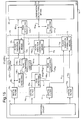
- Fig. 8 represents a signal processing system according to a second comparative example of a combinational weighing machine structured as shown in Fig. 7. It is to be noted that this processing system is importantly different from the system shown in Fig. 1 in that there are no load cells identified specifically as dummy cells. As explained above with reference to Fig.
- the CPU 45 like the CPUs 9 and 9 1 described above with reference to Figs. 2 and 5, carries out vibration corrections and combinational calculations but by using only the digital weight signals W 1 -W m because there are no dummy cells outputting dummy signals.
- the CPU 45 contains digital filters 46 1 -46 m .
- the weight signals W 1 -W m which are selectively outputted from the multiplexer 42 and converted into digital signals by the A/D converter 44, are passed through a switching circuit 47 and corresponding one of the digital filters 46 1 -46 m such that components with relatively high frequencies generated principally when objects to be weighed are put inside the weigh hoppers 65 1 -65 m are eliminated.
- Numeral 48 indicates a combination calculating means which functions like the one shown at 20 in Figs. 2 and 5.
- Digital weight signals W 1 -W m pass through floor vibration correcting means 50 (similar to the means 14 1 -14 m described above) and are inputted into the combination calculating means 48 as vibration corrected weight signals BS 1 -BS m .
- Combinations of these vibration corrected weight values are calculated and particular one of them satisfying a preset criterion is selected.
- the combination calculating means 48 outputs an open signal OS to cause the weighed objects to be dropped from the corresponding hoppers 65 1 -65 3 to the chute 69.
- the vibration components of the weight signals W i -W m shown in Fig. 9 become the same as those of the floor vibrations. It now goes without saying that the load sensors 41 i -41 m may include any of the load sensors 41 1 -41 3 which are selected.
- Another function of the combination calculating means 48 is to treat those of the weight signals W i -W m which were not selected in the preceding cycle of combinational calculations and output them as digital dummy signals D i -D m to a floor vibration calculating means 49 for calculating the vibration mode of the floor on the of the vibration components of the received dummy signals D i -D m to thereby calculate the vertical displacements of the floor at the position, of the load sensors 41 l -41 m and to output displacement signal S l -S m indicative of the calculated displacements to the floor vibration correcting means 50.
- the floor vibration correcting means 50 serves to use the received displacement signals S 1 -S m to correct the weight signals W 1 -W m , that is, to subtract the effects of the floor vibrations represented by the displacement signals S 1 -S m from the weight values of the weighed objects represented by the weight signals W 1 -W m , thereby eliminating the effects of low-frequency floor vibrations and generating and outputting vibration corrected weight signals BS 1 -BS m representing vibration corrected weight values.
- the combination calculating means 48 receives these vibration corrected weight signals BS 1 -BS m and outputs an open signal OS to those of the hopper gate drivers 68 1 -68 m corresponding to selected ones of the load sensors 41 1 -41 m by the combinational calculations, causing weighed objects to be discharged from the corresponding ones of the weigh hoppers 65 1 -65 m to the collector chute 69.
- This allows the cutoff frequencies of the filters 46 1 -46 m to be set relatively high and reduces the time required for the combinational calculations.
- the method of calculating the vertical displacements was already explained above with reference to the weighing machine according to the first comparative example and hence will not be repeated here.
- Fig. 10 shows the structure of another CPU 45' which may be substituted for the CPU 45 shown in Fig. 9, being different therefrom in the following two aspects.
- the CPU 45' additionally includes a cell sensitivity setting means 55 and a cell sensitivity correcting means 56.
- the cell sensitivity setting means 55 serves to preliminarily set a cell sensitivity ratio among the scale cells 67 1 -67 m on the basis of the spring constant of the scale cells 67 1 -67 m and the loads on the scale cells 67 1 -67 m when no objects to be weighed are in the corresponding weigh hoppers 66 i -66 m .
- the cell sensitivity correcting means 56 is for using the cell sensitivity ratio set by the cell sensitivity setting means 55 to thereby correct the dummy signals D i -D m and generating cell sensitivity corrected signals CS i -CS n .
- a weight sensitivity calculating means 57 and a weight sensitivity correcting means 58 are for correcting the changes in sensitivity to the floor vibrations due to changes in the applied load.
- FIG. 11 Another signal processing system according to a third comparative example described next with reference to Fig. 11.
- this signal processing system is described as applied not to a combinational weighing machine with a plurality of weighing units but only to a combination of one weighing unit 81 having a weigh hopper 82 and a scale cell 83 and a vibration-detecting cell 84 which may be an equivalent of a dummy cell shown in Fig. 1 or one of the scale cells shown in Fig. 8 not selected in the preceding cycle of combinational calculations.
- this signal processing system described in Fig. 11 may be interpreted as being applied to a part of a combinational weighing machine.
- the scale cell 83 When an object X to be weighed is placed inside the weigh hopper 82, the scale cell 83 outputs an analog weight signal W.
- the vibration-detecting cell 84 is attached through a frame FR to the same floor F as the scale cell 83 and is adapted to output an analog floor vibration signal V indicative of the vibratory motion of the floor F.
- the signals W and V from these two cells 83 and 84 are amplified by amplifiers 85 and 86 and converted into digital signals by means of analog-to-digital (A/D) converters 87 and 88, respectively.
- A/D analog-to-digital
- the digitalized weight and floor vibration signals W and V are received by a CPU 89 provided with digital filters 90 and 91 for removing therefrom high-frequency vibration components introduced mainly when the object X is loaded, a floor vibration correcting means 92 for removing the digital floor vibration signal V from the digital weight signal W, a repeating means 93 to be described below and a repetition frequency setting means 94 for setting the number of repetitions for the repeating means 93.
- the floor vibration correcting means 92 includes a cell sensitivity correcting means 95 for correcting the sensitivity difference of the cells 83 and 84 with respect to the floor vibrations by adjusting the signal level of the floor vibration signal V, a weight sensitivity correcting means 96 for correcting the sensitivity of the scale cell 83 caused by the application of the load due to the object X, and a subtracting means 97 for subtracting the digital floor vibration signal V from the digital weight signal W to thereby output a vibration-corrected weight signal W indicative of the weight (as mass) m of the object X with the effects of the floor vibrations removed.
- the cell sensitivity correcting means 95 and the weight sensitivity correcting means 96 may alternatively be adapted to adjust the signal level of digital weight signal W to correct the sensitivity difference of the cells 83 and 84 with respect to the floor vibrations or that against changes in the load applied thereon.
- the repeating means 93 is for inputting into the weight sensitivity correcting means 96 the weight m of the object X outputted from the subtracting means 97 and causing the weight sensitivity correction of the scale cell 83 repeated by the number of times specified by the repetition frequency setting means 94 (say, twice).
- the analog weight signal W outputted from the scale cell 83 indicative of the weight of the object X is amplified by the amplifier 85 and then passed through the A/D converter 87 to be converted into a digital signal. Subsequently, this digital weight signal w is received by the CPU 89, passed through the digital filter 90 to have relatively high-frequency vibration components removed therefrom and inputted into the floor vibration correcting means 92.
- the analog floor vibration signal V outputted from the vibration-detecting cell 84 is amplified by the amplifier 86 and then converted into a digital signal by passing through the A/D converter 88.
- This digital floor vibration signal is inputted into the CPU 89, passed through the digital filter 91 and inputted into the floor vibration correcting means 92 after relatively high-frequency vibration components are removed.
- the digital floor vibration signal V has its level adjusted by the cell sensitivity correcting means 95 and the sensitivity difference of the cells 83 and 84 with respect to the floor vibrations is corrected.
- the weight sensitivity correcting means 96 serves to correct, on the basis of the digital weight signal W, the sensitivity difference of the cells 83 and 84 due to application of the weight of the object X.
- the sensitivity corrected digital floor vibration signal V is subtracts by the subtracting means 97 from the digital weight signal W to thereby generate and output a vibration corrected signal W indicative of the mass m of the object X.
- the factor (M + m)/M represents the weight sensitivity ratio between the cells 83 and 84.
- the scale cell 83 is subjected not only to fte initial load M but also to the weight m of the object X, but the vibration-detecting cell 84 is not subjected to such an additional load.
- the sensitivity against the floor vibrations becomes (M + m)/M times greater for the scale cell 83 as compared to the vibration-detecting cell 84. In other words, a correction due to the mass m of the object X becomes desirable.
- the mass m is not of a preliminarily known value but is a target value to be determined. In other words, its value is not determined at the time of the correction operations.
- the weight sensitivity of the scale cell 83 is not corrected at once, but by a feedback process whereby the vibration component V is first detected by the vibration-detecting cell 84, the corrected weight signal W c (t) is calculated by the floor vibration correcting means 92 by (20) and the corrected weight signal W c (t) thus obtained is then fed back into the weight sensitivity correcting means 96.
- This feedback process is repeated by the repetition number set by the repetition frequency setting means 94, such as twice, to improve the accuracy of weight sensitivity correction.
- Fig. 11 shows an embodiment with one scale cell and one vibration-detecting cell, this embodiment is applicable equally well to a situation with one or more scale cells and a plurality of vibration-detection cells such that the vibration mode of the floor is determined on the basis of the vibration component of the floor detected by the vibration-detection cells to calculate the vertical displacements of the floor at the position of each of the scale cells.
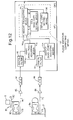
- Fig. 12 is a block diagram of still another signal processing system according to a fourth comparative example which is similar in part to the system described above with reference to Fig. 11. So, the components therein which are substantially identical to corresponding ones shown in Fig. 11 are indicated by the same numerals and will not be explained again in detail.
- the CPU 89' for the system shown in Fig. 12 is different from the CPU 89 of Fig. 11 firstly in that it includes a first zero-point adjusting means 103 and a second zero-point adjusting means 104 for carrying out a zero-point adjustment respectively on the weight signal W and the floor vibration signal V digitalized by the digital filters 90 and 91 and outputting weight component W(t) corresponding to the weight m of the object X and floor vibration component V(t) corresponding to the floor vibrations.
- These components W(t) and V(t) are received by a floor vibration correcting means 103 for correcting the floor vibration component according to a fomula to be described below to thereby output the mass m of the object X.
- the first zero-point adjusting means 103 is for detecting the weight signal level when the weight m of the object X is not being applied, either during a specially set zero-detecting time period before the day's weighing operation is started or during a regular weighing operation, storing it as the zero-level and subtracting this zero-level from the weight signal W outputted from the scale cell 83 loaded with the object X to thereby obtain a zero-adjusted weight signal, that is, the weight component W(t) corresponding to the weight m of the object X.
- the second zero-point adjusting means 104 is for passing the floor vibration signal V outputted from the vibration-detecting cell 84 during such a specially set zero-detecting time period through a strong filter, storing its output as the zero-level, and subtracting this zero-level from the floor vibration signal V to thereby obtain a zero-adjusted floor vibration signal, or the vibration component V(t) corresponding to the floor vibrations.
- the floor vibration correcting means 102 includes a cell sensitivity setting means 105, an initial load setting means 106 and a weight calculating means 107.
- the cell sensitivity setting means 105 is for setting the sensitivity ratio ⁇ between the scale cell 83 when it is not loaded with any object and the vibration-detecting cell 84.
- the initial load setting means 106 is for setting the initial load M on the scale cell 83 when it is not loaded with any object.
- the weight calculating means 107 is for using the cell sensitivity ratio ⁇ set in the cell sensitivity setting means 105 and the initial load M stored in the initial load setting means 106 to calculate the mass m of the object X.
- the sensitivity ratio ⁇ and the initial load M are characteristic to the weighing machine and hence of known values.
- the formula used by the weight calculating means 107 to calculate the weight (as mass) m of the object X is obtained by setting the left-hand side of (20) equal to m. This is because, as (20) is used repeatedly by initially setting m equal to an appropriate initial value, the left-hand side of (20), or the corrected value W c (t), eventually approaches the value to be treated as m.
- m ⁇ W(t) - ⁇ V(t) ⁇ / ⁇ 1 + ( ⁇ /M)V(t) ⁇
- W(t) is the output from the scale. cell after the zero-point adjustment (or weight component) and V(t) is the floor vibration component.
- the digital weight signal W before the object X is placed in the weigh hopper 82 (for example, during a specially set zero-detecting time period before the day's continuous weighing operation is started or even during a regular weighing operation) is inputted into the first zero-point adjusting means 103 and its signal level is detected and stored as the zero-level.
- the digital vibration detecting signal V outputted from the vibration-detecting cell 84 is inputted into the second zero-point adjusting means 104 so as to be passed through a strong filter therein. The output therefrom is stored as the zero-level.
- the sensitivity ratio ⁇ between the scale cell 83 when it is not loaded with any object and the vibration-detecting cell 84 is inputted into and stored in the cell sensitivity setting means 105.
- the initial load M of the scale cell 83 when it is not loaded with any object is inputted into and stored in the initial load setting means 106.
- an object X to be weighed is received by the weigh hopper 82, and the analog weight signal outputted from the scale cell 83 is amplified by the amplifier 85 and converted by the A/D converted 87 into a digital weight signal W.
- This digital weight signal is then inputted into the CPU 89' and, after its relatively highfrequency vibration components are removed by the digital filter 90, is passed through the first zero-point adjusting means 103.
- the weight component W(t) corresponding to the weight m of the object X after the zero-point adjustment is then inputted into the weight calculating means 107 of the floor vibration correcting means 102.
- the analog floor vibration signal V outputted from the vibration-detecting cell 84 is amplified by the amplifier 86 and then converted into a digital floor vibration signal by the A/D converter 88.
- This digital floor vibration signal is inputted into the CPU 89' and, after its relatively high-frequency vibration components are removed by the digital filter 91, is passed through the second zero-point adjusting means 104 to be inputted into the weight calculating means 107 as the floor vibration component V(t) after a zero-point adjustments.
- the weight calculating means 107 thereupon uses the earlier inputted values of the cell sensitivity ratio ⁇ and the initial load M on the scale cell 83 to perform the calculation according to (21) to output the value of the weight m of the object X.
- This embodiment is advantageous in that the mass m of a loaded object X can be immediately calculated by a formula by using preliminarily inputted values of the initial load M and the sensitivity ratio ⁇ such that no time-consuming feedback process of repeating weight sensitivity correction is required.
- this emdiment makes it possible to carry out accurate weighing quickly by performing a weight value calculation only once by using preliminarily inputted constant values.
- Fig. 12 shows an example with one scale cell and one vibration-detecting cell
- this embodiment too is applicable equally well to situations with one or more scale cells and a plurality of vibration-detection cells such that the vibration mode of the floor is determined on the basis of the vibration components of the floor detected by the vibration-detection cells to calculate the vertical displacements of the floor at the position of each of the scale cells.
- the CPUs such as shown in Fig. 2 at 9 and in Fig. 9 at 45, may be provided also with another set of stronger filters with a very low cutoff frequency and a long stabilizing time in addition to ordinary filters.
- filters are highly efficient but do not stabilize within the period of the weighing cycle.
- automatic switches may be further provided such that vibration corrected data will be used as output signals if they participate in combinational calculations continuously but the data filtered through these additional filters will be used as output signals if they do not participate in combinational calculations continuously and the filters are given enough time to stabilize.
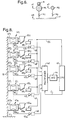
- Fig. 13 which shows a CPU 9 2 according to a first embodiment of the invention
- digital filters (of a first kind) 10 1 -10 m and 11 l -11 m are adapted to receive digitalized weight signals W 1 -W m and dummy signals D 1 -D n sequentially as explained above through a switching circuit 12, and the vibration components with relatively high frequencies are thereby eliminated.
- Numeral 115 indicates a correction circuit consisting essentially of a floor vibration calculating means 13 and floor vibration correcting means 14 1 -14 m as explained above with reference to Fig. 2.
- Numerals 116 1 -116 m indicate a set of filters (of a second kind) characterized as having a relatively low cutoff frequency for eliminating the low-frequency vibration components of the floor, each connected in parallel to corresponding one of the floor vibration correcting means 14 1 -14 m so as to receive the weight signals W 1 -W m and output signals FW 1 -FW m with the vibration components of the floor removed.
- Correction control means 120 1 -120 m individually associated with the floor vibration correcting means 14 1 -14 m , include component detecting means 121 1 -121 m , reference value setting means 122 1 -122 m and comparing means 123 1 -123 m , in addition to the aforementioned digital filters of the second kind 116 1 -116 m .
- the component detecting means 121 1 -121 m serve to compare the digital weight signals W 1 -W m before they are passed though the digital filters of the second kind 116 1 -116 m and the corrected weight signals FW 1 -FW m after they have passed therethrough to thereby determine the vibration components of the floor.
- the reference value setting means 122 1 -122 m are for setting and inputting reference values RefH 1 -RefH m for the amplitudes of the vibration components of the floor.
- the comparing means 123 1 -121 m are for comparing the amplitudes H 1 -H m of the floor vibration components obtained by the component detecting means 121 1 -121 m with the inputted reference values RefH 1 -RefH m .
- the comparing means 123 1 -123 m is adapted to carry out the comparison operations only during a preset time interval in response to a command signal C 1 outputted from a command means 119.
- the correction control means 120 1 -120 m serve to stop the operations of the floor vibration correcting means 14 1 -14 m in response to stop signals ST 1 -ST m outputted from the comparing means 121 t -123 m when H 1 ⁇ RefH 1 ,... or H m ⁇ RefH m , and to operate the floor vibration correcting means 14 1 -14 m in response to correction drive signals DR 1 -DR m from the comparing means 123 1 -123 m when the amplitudes H 1 -H m are respectively greater than the reference values RefH 1 -RefH m .
- the operations of these component detecting means 121 1 -121 m will be explained next with reference to one of them (121 1 ).
- the command means 119 is adapted to output the command signal C 1 at a preset time when decision is to be made whether floor vibration correction must be carried out. Such time may be set some time before the beginning of the daily weighing operation. If the command signal C 1 is received, the associated comparing means 123 1 is activated and outputs a stop signal ST 1 to the correction circuit 115 to stop the operation of the corresponding floor vibration correcting means 14 1 if any, all or the average of the amplitudes H 1 detected during the specified time la less than the reference value RefH 1 .
- the CPU 9 2 is also provided with manually operated selection switches 127 1 -127 m for selectably allowing or not allowing the stop and drive signals ST 1 -ST m and DR 1 -DR m from the comparing means 123 1 -123 m of the correction control means 120 1 -120 m to be transmitted to the floor vibration correcting means 14 1 -14 m of the correction circuit 115.
- these selection switches 127 1 -127 m alloy the user to manually change the mode of control of the correction circuit 115 by the correction control means 120 1 -120 m , in response to the condition of the weighing operations or a change in environmental conditions.
- the selection switches 127 1 -127 m may be set in ON conditions to allow the stop and drive signals ST 1 -ST m and DR 1 -DR m to pass therethrough but, when it is known that a vibration-causing operation is going to take place, the user may manually set the selection switches 127 1 -127 m in OFF conditions to disallow the signals ST 1 -ST m and DR 1 -DR m to pass therethrough and to stop the operations of the floor vibration correcting means 14 1 -14 m such that the weight signals W 1 -W m from the first digital filters 10 1 -10 m are directly inputted to the combination calculating means 20.
- the user can cause the floor vibration correcting means 14 1 - 14 m to operate all the time independent of the magnitude of the floor vibrations also by preventing the signals ST 1 -ST m and DR 1 -DR m from passing through the selection switches 127 1 -127 m .
- the weight signals W 1 -W m are inputted to the stronger digital filters (of the second kind) 116 1 -116 m which allow the component detecting means 121 1 -121 m to determine the vibration components of the floor.
- the comparing means 123 1 -123 m , of the correction control means 120 1 -110 m compare the amplitudes H 1 -H m of these vibration components with the reference values RefH 1 -RefH m in response to the command signal C 1 from the command means 119 such that the operations of the correction circuit 115 can be stopped, depending on the results of comparison therebetween according to any preset criterion such that the weight signals W 1 -W m are directly inputted to the combination calculating means 20.
- Fig. 14 shows still another CPu 9 3 , which is similar to the one described above with reference to Fig. 13 and shown at 9 2 therein, being different therefrom firstly in that a single correction control means 120 (instead of the plurality of correction control means 120 1 -120 m of Fig. 13) is connected to the output side of the digital filters 11 1 -11 n so as to receive the digital dummy signals D 1 -D n therefrom and secondly in that this single control correction control means 120 is provided with a single comparing means 123.
- a single correction control means 120 instead of the plurality of correction control means 120 1 -120 m of Fig. 13
- this single control correction control means 120 is provided with a single comparing means 123.
- the single correction control means 120 includes n-number of stronger digital filters (of the second kind) 116 1 -116 n and component detecting means 121 1 -121 n , as do the correction control means 120 1 -120 m of Fig. 13 together, such that the dummy signals D 1 -D n as outputted from the digital filters 11 1 -11 n and the corrected dummy signals FD 1 -FD n after they have passed through the digital filters of the second kind 116 1 -116 n are compared and the vibration components of the floor are thereby determined.
- the amplitudes H 1 -H n of these vibration components determined by the component detecting means 121 1 -121 n are received by the single comparing means 123, which is activated during a specified period of time (as the comparing means 123 1 -113 m of the correction control means 120 1 -120 m of Fig. 13 are activated by the command signal C 1 as explained above), and compared thereby with a single reference value RefH set inside a reference value setting means 122.
- the comparing means 123 is programmed to compare the reference value RefH with either the maximum or the minimum of the amplitudes K 1 -H n and output a stop signal ST1 or a drive signal DR1 accordingly, as explained above with reference to Fig. 13.
- the CPU 9 3 shown in Fig. 14 is identical to the CPU 9 2 in Fig. 13, and those components which are identical or equivalent to each other are indicated by the same numerals. It goes without saying that the CPU 9 3 of Fig. 14 may also be provided with a command means as indicated at 119 in Fig. 13 such that the time for activation of the single comparing means 123 can be controlled by outputting a command signal.
- Fig. 15 shows still anaother CPU 9 4 , which may be viewed as another variations of the CPU 9 2 shown in Fig. 13, characterized as including peak detecting means of a first kind 130 1 -130 m for detecting peak value P 1 of the digital weight signals W 1 -W m outputted from the scale cells 3 1 -3 m and peak detecting means of a second kind 131 1 -131 m for detecting (second) peak value P 2 of the vibration corrected weight signal BS 1 -BS m outputted from the floor vibration correcting means 14 1 -14 m of the correction circuit 115.
- peak value comparing means 135 1 -133 m for using these second peak value P 2 as a reference value and comparing the first peak value P 1 therewith.
- Neither the digital filters of the second kind 116 1 -116 n nor the command means 119 shown in Fig. 13 find their equivalents in the CPU 9 4 , although a command means may be included such that the peak value comparing means 135 1 -135 m may be activated only during a specified time interval.
- the peak value comparing means 135 1 -135 m may be programmed to output a stop signal ST1 to the correction circuit 115 to stop the operations of the corresponding floor vibration correcting means 14 1 -14 m if any of the (first) peak values P 1 detected during a predetermined time interval is less than the reference peak value P 2 ("minimum” condition), if all of such first peak values P 1 are less than the reference value P 2 ("maximum” condition), or if the average of them is loss than the reference value P 2 .
- the advantage of this CPU 9 4 is that the operation of any of the floor vibration correcting means 14 1 -14 m is stopped if its corresponding first peak value P 1 is less (whether in the sense of "minimum”, “maximum” or average as explained above) than a predetermined reference value (represented by the second peak value P 2 ) so as to reduce the errors which may be generated due to vibration corrections.
- Fig. 15 is identical to Fig. 13 and those components which are identical or equivalent to each other are indicated by the same numerals.
- Fig. 16 shows Still another CPU 9 5 adapted to stop or continue the operations of its correction circuit 115, depending on the magnitudes of the amplitudes of the dummy signals D 1 -D n .
- digital filters of the second kind 116 1 -116 n are adapted to receive the dummy signals D 1 -D n , to remove therefrom the vibration components of the floor and to thereby output vibration corrected DC dummy signals FD 1 -FD n to zero point adjusting means 142 1 -142 n of zero point adjusting setting units 141 1 -141 n .
- These inputted signals FD 1 -FD n are stored in memory devices (MEM) 143 1 -143 n as zero points, and zero point signals Rz 1 -Rz n indicative of the zero points are outputted from zero point outputting means 144 1 -144 n .
- MEM memory devices
- a zero point adjustment command means 147 adapted to output a command signal C 2 at a preset timing during a weighing operation, may, every 30 minutes.
- the zero point adjusting means 142 1 -142 n receive the command signal C 2 , they accept the DC dummy signals FD 1 -FD n for a predetermined length of time such as 10 seconds, thereby adjusting the zero points on the basis of these signals FD 1 -FD n , say, from their average values. If zero points are already known, a simple means for outputting a zero point may be used in place of the zero point adjusting setting units 141 1 -141 n .
- the dummy signals D 1 -D n are also inputted into amplitude detecting means 145 1 -145 n , which are adapted to detect the amplitudes H 1 -H n of the dummy signals D 1 -D n on the basis of the ditferences between the dummy signals D 1 -D n and the zero point signals Rz 1 -Rz n received from the zero point outputting means 144 1 -144 n .
- the amplitudes H 1 -H n thus detected by the amplitude detecting means 145 1 -145 n , are received by a comparing means 123 and compared thereby with a reference amplitude value RefH set in a reference value setting means 122.
- the comparing means 123 outputs a stop signal ST to the correction circuit 115 if any of the detected amplitudes H 1 -H n is smaller than the reference amplitude value RefH (minimun condition), if all of the detected amplitudes H 1 -H n are smaller than the reference amplitude value RefH (maximum condition), or if the average of the detected amplitudes H 1 -H n is smaller than the reference amplitude value RefH.
- Fig. 17 shows still another CPU 9 6 adapted to stop or continue the operations of its correction circuit 115, but depending on the magnitudes of the amplitudes of the digital weight signals W 1 -W m outputted from the scale cells 3 1 -3 m , rather than of the dummy signals D 1 -D n , and provided with a plurality of correction control means 120 1 -120 m corresponding individually to the m-number of load sensors 1 1 -1 m (Fig. 1).
- the zero point adjustment command means 147 is adapted to output a command signal C 2 at preset times when the scale cells 3 1 -3 m are in unloaded conditions such as every morning before the daily weighing operation is started.
- zero point adjusting setting units 141 1 -141 m are activated for a specified length of time, during which digital weight signals W 1 -W m , while the load sensors 1 1 -1 m are in unloaded conditions, are passed through strong digital filters of the second kind 116 1 -116 m and corrected DC weight signals FW 1 -FW m , are received by zero point adjusting means 142 1 -142 n .
- Zero points are thereby determined, say, from the average of these weight signals W 1 -W m , and stored in memory devices (MEM) 143 1 -143 m .
- MEM memory devices
- Zero point outputting means 144 1 -144 m to output zero point signals Rzz 1 -Rzz m indicative of these zero points when weight signals W 1 -W m are outputted subsequently when the load sensors 1 1 -1 m are in loaded conditions.
- a simple means for outputting a zero point may be used in place of zero point adjusting setting units 141 1 -141 m as explained above with reference to Fig. 16.
- Amplitude detecting leans 145 1 -145 m are adapted to detect the amplitudes H 1 -H m of the weight signals W 1 -W m on the basis of the differences between the weight signals W 1 -W m under the no-load conditions and the zero point signals Rzz 1 -Rzz m received from zero point outputting means 144 1 -144 m .
- the amplitudes H 1 -H m thus detected by the amplitude detecting means 145 1 -145 m are received by comparing means 123 1 -123 m and compared thereby with reference amplitude values RefH 1 -RefH m set in reference value setting means 122 1 -122 m .
- the comparing means 123 1 -123 m output stop signals ST 1 -ST m to the correction circuit 115 in the same manner as explained above with reference to Fig. 13.
- a plurality of correction control means corresponding individually to the n-number of dummy cells 4 1 -4 n may be provided as shown in Fig. 17.
- a single correction control means may be provided in common for all load sensors 1 1 -1 m (Fig. 1).
- correction circuit 115 in all of the embodiments described above, is controlled by correction control means 120 for detecting vibration components contained in weight signals W 1 -W m or dummy siqnals D 1 -D n , displacement signals S 1 -S m representing the vertical motion of the floor may be used to determine whether floor vibration corrections are necessary or not, as shown in Fig. 18.
- Fig. 18 shows such a CPU 9 7 .
- the CPU 9 7 according to this embodiment includes a floor vibration calculating means 13 adapted to calculate the vibration mode of the floor from the vibration components of the dummy signals D 1 -D n and to output displacement signals S 1 -S m indicative of the vertical displacements of the floor at the positions of the scale cells 3 1 -3 m .
- the CPU 9 7 also includes m-number of comparing means 123 1 -123 m corresponding to the m-number of scale cells 3 1 -3 m
- These comparing means 123 1 -123 m are adapted to receive the displacement signals S 1 -S m outputted from the floor vibration calculating means 13 and to compare them with reference values RefS 1 -RefS m stored in reference value setting means 122 1 -122 m , outputting stop signals ST 1 -ST m to the floor vibration correcting means 14 1 -14 m if the level of the displacement signals S 1 -S m is lower than that of the reference values RefS 1 -RefS m and drive signals DR 1 -DR m if other wise.
- the floor vibration calculating means 13 can calculate the effects of floor vibrations on the scale cells 3 1 -3 m accurately even where the dummy signals D 1 -D n outputted from the dummy cells 4 1 -4 m do not accurately represent the effects of the floor vibrations on the scale cells 3 1 -3 m because, for example, the scale and dummy cells 3 1 -3 m , 4 1 -4 m are positioned differently.
- the CPU 9 7 as shown in Fig. 18 can stop and activate the correction circuit 115 more appropriately according to the motion of the individual scale cells 3 1 -3 m .
- the correcting circuit may be of a simple structure merely for the purpose of subtracting the vibration compornent from the weight signal.
- the manually operable selection switches 127 1 -127 m may be replaced by automatic switches adapted to function periodically or the correction control means 120 may be additionally adapted to control the operation of the correction circuit 115.
- the invention has many aspects, each of which can be realized in many different forms.
- these aspects of the invention were not necessarily presented all at once in any of the embodiments.
- these different aspects of the invention presented herein are intended to be freely combined to produce further embodiments of the invention.
- the disclosure is intended to be interpreted broadly, and all modifications and variations of the disclosed embodiments that may be apparent to persons skilled in the art are intended to be within the scope of the invention.
Landscapes
- Physics & Mathematics (AREA)
- General Physics & Mathematics (AREA)
- Weight Measurement For Supplying Or Discharging Of Specified Amounts Of Material (AREA)
- Measurement Of Levels Of Liquids Or Fluent Solid Materials (AREA)
Abstract
Description
Claims (7)
- A weighing machine comprising:a scale cell for weighing an object and outputting a weight signal indicative of measured weight value of said object;a vibration-detecting cell set on a same floor as said scale cell for outputting a floor vibration signal indicative of the vibration of said floor;correcting means (14) for correcting said weight signal on the basis of said floor vibration signal outputted from said vibration-detecting cell and thereby generating vibration corrected signal indicative of corrected weight value of said object not containing effects of said vibration of said floor; andcorrection control means (120) for detecting vibration components of said floor and stopping operations of said correcting means by comparing said vibration components with a reference value.
- The weighing machine of claim 1, wherein said correction control means includes:a filter which is connected to said scale cell in parallel with said correcting means so as to receive said weight signal from said scale cell; andvibration component detecting means for comparing said weight signal before and after passing through said filter and thereby detecting vibration components of said floor;said weighing machine further comprising command means for causing a comparison to be made between said vibration components and said reference value during a preset comparison time interval.
- The weighing machine of claim 1, wherein said correction control means includes:a filter which is connected to said vibration-detecting cell in parallel with said correcting means so as to receive said floor vibration signal from said vibration detecting cell; andvibration component detecting means for comparing said weight signal before and after passing through said filter and thereby detecting vibration components of said floor;said weighing machine further comprising command means for causing a comparison to be made between said vibration components and said reference value during a preset comparison time interval.
- The weighing machine of claim 1, further comprising:first peak detecting means for detecting peaks in said weight signal from said scale cell; andsecond peak detecting means for detecting peaks in a vibration-corrected signal outputted from said correcting means;said correction control means including peak comparing means for using a peak detected by said second peak detecting means as said reference value and comparing a peak detected by said first peak detecting means with said reference value.
- The weighing machine of claim 1, wherein said correction control means includes:zero-point adjusting means for operating during a specified zero-point adjusting time interval, storing a zero-point level indicated by a zero-point signal obtained by removing said vibration components from said weight signal, and thereby outputting a zero-point signal indicative of said zero-point level; andamplitude detecting means for detecting the amplitude of said floor vibration signal from the difference between said floor vibration signal and said zero-point signal.
- The weighing machine of claim 1, wherein said correction control means includes:zero-point adjusting means for operating during a specified zero-point adjusting time interval, storing a zero-point level indicated by a zero-point signal obtained by removing said vibration components from a no-load weight signal outputted from said scale cell when no load is being applied thereto from any object, and thereby outputting a zero-point signal indicative of said zero-point level; andamplitude detecting means for detecting the amplitude of said no-load weight signal from the difference between said no-load weight signal and said zero-point signal.
- The weighing machine of claim 1, wherein said vibration-detecting cell is one of a plurality of similar vibration-detecting cells and said correcting means include:vibrating calculating means for detecting vibration modes of said floor from vibration components of floor vibration signals outputted from said plurality of vibration-detecting cells and thereby calculating vertical displacement of said floor at the position of said scale cell; andvibration correcting means for generating a vibration-corrected signal by removing said vibration components from said weight signal by using said vertical displacement;said correction control means including comparing means for comparing said vertical displacement calculated by said vibration calculating means with said reference value.
Applications Claiming Priority (16)
| Application Number | Priority Date | Filing Date | Title |
|---|---|---|---|
| JP12785693A JP3251707B2 (en) | 1993-04-30 | 1993-04-30 | Combination weighing device |
| JP12785593A JP3251706B2 (en) | 1993-04-30 | 1993-04-30 | Weighing device |
| JP12785693 | 1993-04-30 | ||
| JP127856/93 | 1993-04-30 | ||
| JP127855/93 | 1993-04-30 | ||
| JP12785593 | 1993-04-30 | ||
| JP343540/93 | 1993-12-15 | ||
| JP34354093A JP3422546B2 (en) | 1993-12-15 | 1993-12-15 | Floor vibration correction method and apparatus |
| JP34353993 | 1993-12-15 | ||
| JP34353993A JP3765105B2 (en) | 1993-12-15 | 1993-12-15 | Floor vibration correction method and apparatus |
| JP34354093 | 1993-12-15 | ||
| JP343539/93 | 1993-12-15 | ||
| JP35270093 | 1993-12-31 | ||
| JP352700/93 | 1993-12-31 | ||
| JP35270093A JP3251754B2 (en) | 1993-12-31 | 1993-12-31 | Weighing device with floor vibration compensation |
| EP19940303195 EP0622617B1 (en) | 1993-04-30 | 1994-05-03 | Weighing machine with at least three dummy cells |
Related Parent Applications (1)
| Application Number | Title | Priority Date | Filing Date |
|---|---|---|---|
| EP19940303195 Division EP0622617B1 (en) | 1993-04-30 | 1994-05-03 | Weighing machine with at least three dummy cells |
Publications (2)
| Publication Number | Publication Date |
|---|---|
| EP0818669A1 true EP0818669A1 (en) | 1998-01-14 |
| EP0818669B1 EP0818669B1 (en) | 2001-09-26 |
Family
ID=27527156
Family Applications (2)
| Application Number | Title | Priority Date | Filing Date |
|---|---|---|---|
| EP19940303195 Expired - Lifetime EP0622617B1 (en) | 1993-04-30 | 1994-05-03 | Weighing machine with at least three dummy cells |
| EP97202733A Expired - Lifetime EP0818669B1 (en) | 1993-04-30 | 1994-05-03 | Weighing machine with stoppage of vibration correction |
Family Applications Before (1)
| Application Number | Title | Priority Date | Filing Date |
|---|---|---|---|
| EP19940303195 Expired - Lifetime EP0622617B1 (en) | 1993-04-30 | 1994-05-03 | Weighing machine with at least three dummy cells |
Country Status (3)
| Country | Link |
|---|---|
| EP (2) | EP0622617B1 (en) |
| DE (2) | DE69428463T2 (en) |
| ES (2) | ES2119964T3 (en) |
Cited By (3)
| Publication number | Priority date | Publication date | Assignee | Title |
|---|---|---|---|---|
| EP0743509A2 (en) * | 1995-05-16 | 1996-11-20 | ISHIDA CO., Ltd. | Method, apparatus and system for combinational weighing by ranks |
| US6558721B1 (en) * | 1998-04-03 | 2003-05-06 | Ishida Co., Ltd. | Apparatus and method for distributing a particulate charge over an article |
| EP2159554A1 (en) * | 2008-08-29 | 2010-03-03 | Mettler-Toledo AG | Method for monitoring the status of a power measuring device, power measuring device and power measuring module |
Families Citing this family (5)
| Publication number | Priority date | Publication date | Assignee | Title |
|---|---|---|---|---|
| JPH07121732B2 (en) * | 1992-12-17 | 1995-12-25 | 株式会社イシダ | Film supply device in packaging machine |
| JP3539582B2 (en) * | 1993-12-02 | 2004-07-07 | 株式会社イシダ | Multi-point cell type weighing device |
| EP0756158B1 (en) * | 1995-07-26 | 2002-10-02 | ISHIDA CO., Ltd. | Weighing apparatus |
| JPH11108751A (en) * | 1997-10-08 | 1999-04-23 | Ishida Co Ltd | Measuring device with filter automatic regulating function |
| DE102008062972B4 (en) | 2008-12-23 | 2012-04-12 | Wipotec Wiege- Und Positioniersysteme Gmbh | Device for vibration compensation of the weight signal of a weighing sensor |
Citations (7)
| Publication number | Priority date | Publication date | Assignee | Title |
|---|---|---|---|---|
| FR2418451A1 (en) * | 1978-02-24 | 1979-09-21 | Mettler Instrumente Ag | ELECTRICAL INSTRUMENT FOR MEASURING A MASS |
| EP0122796A1 (en) * | 1983-04-14 | 1984-10-24 | Kabushiki Kaisha Ishida Koki Seisakusho | Weighing apparatus |
| EP0129249A2 (en) * | 1983-06-21 | 1984-12-27 | Kabushiki Kaisha Ishida Koki Seisakusho | Weighing machine |
| EP0418567A1 (en) * | 1989-08-25 | 1991-03-27 | Tokyo Electric Co., Ltd. | Device for measuring a force, particularly a weight |
| EP0429725A1 (en) * | 1989-11-29 | 1991-06-05 | Yamato Scale Company, Limited | Device and method for filtering weight indicative signal from weighing device |
| EP0430695A2 (en) * | 1989-12-01 | 1991-06-05 | ISHIDA CO., Ltd. | Weighing apparatus |
| EP0432979A2 (en) * | 1989-12-08 | 1991-06-19 | Yamato Scale Co., Ltd. | Scale for operation under oscillating conditions |
-
1994
- 1994-05-03 DE DE1994628463 patent/DE69428463T2/en not_active Expired - Lifetime
- 1994-05-03 ES ES94303195T patent/ES2119964T3/en not_active Expired - Lifetime
- 1994-05-03 ES ES97202733T patent/ES2164984T3/en not_active Expired - Lifetime
- 1994-05-03 DE DE1994612335 patent/DE69412335T2/en not_active Expired - Lifetime
- 1994-05-03 EP EP19940303195 patent/EP0622617B1/en not_active Expired - Lifetime
- 1994-05-03 EP EP97202733A patent/EP0818669B1/en not_active Expired - Lifetime
Patent Citations (7)
| Publication number | Priority date | Publication date | Assignee | Title |
|---|---|---|---|---|
| FR2418451A1 (en) * | 1978-02-24 | 1979-09-21 | Mettler Instrumente Ag | ELECTRICAL INSTRUMENT FOR MEASURING A MASS |
| EP0122796A1 (en) * | 1983-04-14 | 1984-10-24 | Kabushiki Kaisha Ishida Koki Seisakusho | Weighing apparatus |
| EP0129249A2 (en) * | 1983-06-21 | 1984-12-27 | Kabushiki Kaisha Ishida Koki Seisakusho | Weighing machine |
| EP0418567A1 (en) * | 1989-08-25 | 1991-03-27 | Tokyo Electric Co., Ltd. | Device for measuring a force, particularly a weight |
| EP0429725A1 (en) * | 1989-11-29 | 1991-06-05 | Yamato Scale Company, Limited | Device and method for filtering weight indicative signal from weighing device |
| EP0430695A2 (en) * | 1989-12-01 | 1991-06-05 | ISHIDA CO., Ltd. | Weighing apparatus |
| EP0432979A2 (en) * | 1989-12-08 | 1991-06-19 | Yamato Scale Co., Ltd. | Scale for operation under oscillating conditions |
Cited By (7)
| Publication number | Priority date | Publication date | Assignee | Title |
|---|---|---|---|---|
| EP0743509A2 (en) * | 1995-05-16 | 1996-11-20 | ISHIDA CO., Ltd. | Method, apparatus and system for combinational weighing by ranks |
| EP0743509B1 (en) * | 1995-05-16 | 2003-07-23 | ISHIDA CO., Ltd. | Method of combinational weighing by ranks |
| US6558721B1 (en) * | 1998-04-03 | 2003-05-06 | Ishida Co., Ltd. | Apparatus and method for distributing a particulate charge over an article |
| EP2159554A1 (en) * | 2008-08-29 | 2010-03-03 | Mettler-Toledo AG | Method for monitoring the status of a power measuring device, power measuring device and power measuring module |
| WO2010023287A1 (en) * | 2008-08-29 | 2010-03-04 | Mettler-Toledo Ag | Method for monitoring the state of a force-measuring apparatus, force-measuring apparatus, and force-measuring module |
| US8258415B2 (en) | 2008-08-29 | 2012-09-04 | Mettler-Toledo Ag | Method of monitoring the free mobility of a force-measuring device and force-measuring module for applying method |
| CN102132135B (en) * | 2008-08-29 | 2013-01-02 | 梅特勒-托利多公开股份有限公司 | Method for monitoring the state of a force-measuring apparatus, force-measuring apparatus, and force-measuring module |
Also Published As
| Publication number | Publication date |
|---|---|
| ES2164984T3 (en) | 2002-03-01 |
| DE69428463D1 (en) | 2001-10-31 |
| DE69412335D1 (en) | 1998-09-17 |
| DE69428463T2 (en) | 2002-05-29 |
| DE69412335T2 (en) | 1999-01-21 |
| ES2119964T3 (en) | 1998-10-16 |
| EP0622617A1 (en) | 1994-11-02 |
| EP0818669B1 (en) | 2001-09-26 |
| EP0622617B1 (en) | 1998-08-12 |
Similar Documents
| Publication | Publication Date | Title |
|---|---|---|
| US5936206A (en) | Weighing machines with means for correcting effects of floor vibrations on weight signals therefrom | |
| USRE36411E (en) | Weighing apparatus with means for correcting effects of vibrations | |
| US6013879A (en) | Multi-point cell type weighing machines | |
| EP0122796B1 (en) | Weighing apparatus | |
| CN100595530C (en) | Weighing device, in particular multiple-track weighing device | |
| US6034334A (en) | Method of and means for correcting effects of floor vibrations on weight signals from a weighing machine | |
| EP0818669B1 (en) | Weighing machine with stoppage of vibration correction | |
| US5736684A (en) | Combinational weighing or counting apparatus | |
| CN113494947B (en) | Metering device | |
| JPH09113348A (en) | Weighing system | |
| EP0674158A2 (en) | Mass measurement method and apparatus | |
| JPH08110261A (en) | Apparatus for mass measurement and apparatus for weight measurement | |
| JP3642639B2 (en) | A weighing device having a plurality of load converting means | |
| JPH09113346A (en) | Method and apparatus for measurement | |
| JP3251707B2 (en) | Combination weighing device | |
| EP4060296A1 (en) | Weighing apparatus | |
| JP3836969B2 (en) | Vibratory conveying device for goods | |
| JP3525364B2 (en) | Weighing method and device | |
| JP3251754B2 (en) | Weighing device with floor vibration compensation | |
| JP3251706B2 (en) | Weighing device | |
| JPH0769207B2 (en) | Combination weighing device | |
| JP2687624B2 (en) | Electronic balance | |
| JP3422546B2 (en) | Floor vibration correction method and apparatus | |
| JPH1164086A (en) | Weighting apparatus | |
| SU1606870A1 (en) | Method and apparatus for weighing |
Legal Events
| Date | Code | Title | Description |
|---|---|---|---|
| PUAI | Public reference made under article 153(3) epc to a published international application that has entered the european phase |
Free format text: ORIGINAL CODE: 0009012 |
|
| AC | Divisional application: reference to earlier application |
Ref document number: 622617 Country of ref document: EP |
|
| AK | Designated contracting states |
Kind code of ref document: A1 Designated state(s): DE ES FR GB IT |
|
| 17P | Request for examination filed |
Effective date: 19980626 |
|
| RTI1 | Title (correction) |
Free format text: WEIGHING MACHINE WITH STOPPAGE OF VIBRATION CORRECTION |
|
| GRAG | Despatch of communication of intention to grant |
Free format text: ORIGINAL CODE: EPIDOS AGRA |
|
| 17Q | First examination report despatched |
Effective date: 20001124 |
|
| GRAG | Despatch of communication of intention to grant |
Free format text: ORIGINAL CODE: EPIDOS AGRA |
|
| GRAH | Despatch of communication of intention to grant a patent |
Free format text: ORIGINAL CODE: EPIDOS IGRA |
|
| GRAH | Despatch of communication of intention to grant a patent |
Free format text: ORIGINAL CODE: EPIDOS IGRA |
|
| GRAH | Despatch of communication of intention to grant a patent |
Free format text: ORIGINAL CODE: EPIDOS IGRA |
|
| GRAA | (expected) grant |
Free format text: ORIGINAL CODE: 0009210 |
|
| AC | Divisional application: reference to earlier application |
Ref document number: 622617 Country of ref document: EP |
|
| AK | Designated contracting states |
Kind code of ref document: B1 Designated state(s): DE ES FR GB IT |
|
| REF | Corresponds to: |
Ref document number: 69428463 Country of ref document: DE Date of ref document: 20011031 |
|
| ET | Fr: translation filed | ||
| REG | Reference to a national code |
Ref country code: GB Ref legal event code: IF02 |
|
| REG | Reference to a national code |
Ref country code: ES Ref legal event code: FG2A Ref document number: 2164984 Country of ref document: ES Kind code of ref document: T3 |
|
| PLBE | No opposition filed within time limit |
Free format text: ORIGINAL CODE: 0009261 |
|
| STAA | Information on the status of an ep patent application or granted ep patent |
Free format text: STATUS: NO OPPOSITION FILED WITHIN TIME LIMIT |
|
| 26N | No opposition filed | ||
| PGFP | Annual fee paid to national office [announced via postgrant information from national office to epo] |
Ref country code: FR Payment date: 20050511 Year of fee payment: 12 |
|
| PGFP | Annual fee paid to national office [announced via postgrant information from national office to epo] |
Ref country code: ES Payment date: 20050624 Year of fee payment: 12 |
|
| PG25 | Lapsed in a contracting state [announced via postgrant information from national office to epo] |
Ref country code: ES Free format text: LAPSE BECAUSE OF NON-PAYMENT OF DUE FEES Effective date: 20060504 |
|
| PGFP | Annual fee paid to national office [announced via postgrant information from national office to epo] |
Ref country code: IT Payment date: 20060531 Year of fee payment: 13 |
|
| REG | Reference to a national code |
Ref country code: FR Ref legal event code: ST Effective date: 20070131 |
|
| REG | Reference to a national code |
Ref country code: ES Ref legal event code: FD2A Effective date: 20060504 |
|
| PG25 | Lapsed in a contracting state [announced via postgrant information from national office to epo] |
Ref country code: FR Free format text: LAPSE BECAUSE OF NON-PAYMENT OF DUE FEES Effective date: 20060531 |
|
| PG25 | Lapsed in a contracting state [announced via postgrant information from national office to epo] |
Ref country code: IT Free format text: LAPSE BECAUSE OF NON-PAYMENT OF DUE FEES Effective date: 20070503 |
|
| PGFP | Annual fee paid to national office [announced via postgrant information from national office to epo] |
Ref country code: DE Payment date: 20110520 Year of fee payment: 18 |
|
| REG | Reference to a national code |
Ref country code: DE Ref legal event code: R119 Ref document number: 69428463 Country of ref document: DE Effective date: 20121201 |
|
| PG25 | Lapsed in a contracting state [announced via postgrant information from national office to epo] |
Ref country code: DE Free format text: LAPSE BECAUSE OF NON-PAYMENT OF DUE FEES Effective date: 20121201 |
|
| PGFP | Annual fee paid to national office [announced via postgrant information from national office to epo] |
Ref country code: GB Payment date: 20130521 Year of fee payment: 20 |
|
| REG | Reference to a national code |
Ref country code: GB Ref legal event code: PE20 Expiry date: 20140502 |
|
| PG25 | Lapsed in a contracting state [announced via postgrant information from national office to epo] |
Ref country code: GB Free format text: LAPSE BECAUSE OF EXPIRATION OF PROTECTION Effective date: 20140502 |