EP0818546B1 - High fatigue strength gear - Google Patents
High fatigue strength gear Download PDFInfo
- Publication number
- EP0818546B1 EP0818546B1 EP97111662A EP97111662A EP0818546B1 EP 0818546 B1 EP0818546 B1 EP 0818546B1 EP 97111662 A EP97111662 A EP 97111662A EP 97111662 A EP97111662 A EP 97111662A EP 0818546 B1 EP0818546 B1 EP 0818546B1
- Authority
- EP
- European Patent Office
- Prior art keywords
- gear
- steel material
- sub
- fatigue strength
- steel
- Prior art date
- Legal status (The legal status is an assumption and is not a legal conclusion. Google has not performed a legal analysis and makes no representation as to the accuracy of the status listed.)
- Expired - Lifetime
Links
- 229910000831 Steel Inorganic materials 0.000 claims description 67
- 239000010959 steel Substances 0.000 claims description 67
- 239000000463 material Substances 0.000 claims description 40
- 238000005121 nitriding Methods 0.000 claims description 30
- 238000011282 treatment Methods 0.000 claims description 28
- 230000032683 aging Effects 0.000 claims description 22
- 238000005242 forging Methods 0.000 claims description 8
- 238000004080 punching Methods 0.000 claims description 7
- 229910052698 phosphorus Inorganic materials 0.000 claims description 5
- 229910052710 silicon Inorganic materials 0.000 claims description 5
- 229910052717 sulfur Inorganic materials 0.000 claims description 5
- 239000002344 surface layer Substances 0.000 claims description 4
- 230000000052 comparative effect Effects 0.000 description 16
- 239000000243 solution Substances 0.000 description 15
- 239000011572 manganese Substances 0.000 description 10
- 238000005452 bending Methods 0.000 description 8
- 239000010949 copper Substances 0.000 description 8
- 239000010410 layer Substances 0.000 description 8
- 230000035882 stress Effects 0.000 description 8
- 239000010936 titanium Substances 0.000 description 8
- 238000001816 cooling Methods 0.000 description 6
- 150000001875 compounds Chemical class 0.000 description 5
- 239000000203 mixture Substances 0.000 description 5
- 238000010791 quenching Methods 0.000 description 5
- 230000000171 quenching effect Effects 0.000 description 5
- 230000002730 additional effect Effects 0.000 description 4
- 229910052799 carbon Inorganic materials 0.000 description 4
- 238000005255 carburizing Methods 0.000 description 4
- 210000000078 claw Anatomy 0.000 description 4
- 238000010438 heat treatment Methods 0.000 description 4
- 238000003754 machining Methods 0.000 description 4
- OKTJSMMVPCPJKN-UHFFFAOYSA-N Carbon Chemical compound [C] OKTJSMMVPCPJKN-UHFFFAOYSA-N 0.000 description 3
- 230000000694 effects Effects 0.000 description 3
- 230000002708 enhancing effect Effects 0.000 description 3
- 238000004519 manufacturing process Methods 0.000 description 3
- 238000005496 tempering Methods 0.000 description 3
- 229910001209 Low-carbon steel Inorganic materials 0.000 description 2
- 229910052782 aluminium Inorganic materials 0.000 description 2
- 229910052802 copper Inorganic materials 0.000 description 2
- 239000013078 crystal Substances 0.000 description 2
- 238000005098 hot rolling Methods 0.000 description 2
- 230000001965 increasing effect Effects 0.000 description 2
- 229910052748 manganese Inorganic materials 0.000 description 2
- 239000012047 saturated solution Substances 0.000 description 2
- 239000000126 substance Substances 0.000 description 2
- 229910052719 titanium Inorganic materials 0.000 description 2
- 238000004804 winding Methods 0.000 description 2
- 229910000859 α-Fe Inorganic materials 0.000 description 2
- RYGMFSIKBFXOCR-UHFFFAOYSA-N Copper Chemical compound [Cu] RYGMFSIKBFXOCR-UHFFFAOYSA-N 0.000 description 1
- PWHULOQIROXLJO-UHFFFAOYSA-N Manganese Chemical compound [Mn] PWHULOQIROXLJO-UHFFFAOYSA-N 0.000 description 1
- 229910000954 Medium-carbon steel Inorganic materials 0.000 description 1
- OAICVXFJPJFONN-UHFFFAOYSA-N Phosphorus Chemical compound [P] OAICVXFJPJFONN-UHFFFAOYSA-N 0.000 description 1
- XUIMIQQOPSSXEZ-UHFFFAOYSA-N Silicon Chemical compound [Si] XUIMIQQOPSSXEZ-UHFFFAOYSA-N 0.000 description 1
- NINIDFKCEFEMDL-UHFFFAOYSA-N Sulfur Chemical compound [S] NINIDFKCEFEMDL-UHFFFAOYSA-N 0.000 description 1
- RTAQQCXQSZGOHL-UHFFFAOYSA-N Titanium Chemical compound [Ti] RTAQQCXQSZGOHL-UHFFFAOYSA-N 0.000 description 1
- XAGFODPZIPBFFR-UHFFFAOYSA-N aluminium Chemical compound [Al] XAGFODPZIPBFFR-UHFFFAOYSA-N 0.000 description 1
- 238000002485 combustion reaction Methods 0.000 description 1
- 238000005520 cutting process Methods 0.000 description 1
- 230000007547 defect Effects 0.000 description 1
- 239000002184 metal Substances 0.000 description 1
- 229910052751 metal Inorganic materials 0.000 description 1
- 150000004767 nitrides Chemical class 0.000 description 1
- 239000011574 phosphorus Substances 0.000 description 1
- 238000005498 polishing Methods 0.000 description 1
- 238000005096 rolling process Methods 0.000 description 1
- 238000007493 shaping process Methods 0.000 description 1
- 239000010703 silicon Substances 0.000 description 1
- 239000011593 sulfur Substances 0.000 description 1
Images


Classifications
-
- C—CHEMISTRY; METALLURGY
- C22—METALLURGY; FERROUS OR NON-FERROUS ALLOYS; TREATMENT OF ALLOYS OR NON-FERROUS METALS
- C22C—ALLOYS
- C22C38/00—Ferrous alloys, e.g. steel alloys
- C22C38/16—Ferrous alloys, e.g. steel alloys containing copper
-
- C—CHEMISTRY; METALLURGY
- C21—METALLURGY OF IRON
- C21D—MODIFYING THE PHYSICAL STRUCTURE OF FERROUS METALS; GENERAL DEVICES FOR HEAT TREATMENT OF FERROUS OR NON-FERROUS METALS OR ALLOYS; MAKING METAL MALLEABLE, e.g. BY DECARBURISATION OR TEMPERING
- C21D9/00—Heat treatment, e.g. annealing, hardening, quenching or tempering, adapted for particular articles; Furnaces therefor
- C21D9/32—Heat treatment, e.g. annealing, hardening, quenching or tempering, adapted for particular articles; Furnaces therefor for gear wheels, worm wheels, or the like
-
- C—CHEMISTRY; METALLURGY
- C23—COATING METALLIC MATERIAL; COATING MATERIAL WITH METALLIC MATERIAL; CHEMICAL SURFACE TREATMENT; DIFFUSION TREATMENT OF METALLIC MATERIAL; COATING BY VACUUM EVAPORATION, BY SPUTTERING, BY ION IMPLANTATION OR BY CHEMICAL VAPOUR DEPOSITION, IN GENERAL; INHIBITING CORROSION OF METALLIC MATERIAL OR INCRUSTATION IN GENERAL
- C23C—COATING METALLIC MATERIAL; COATING MATERIAL WITH METALLIC MATERIAL; SURFACE TREATMENT OF METALLIC MATERIAL BY DIFFUSION INTO THE SURFACE, BY CHEMICAL CONVERSION OR SUBSTITUTION; COATING BY VACUUM EVAPORATION, BY SPUTTERING, BY ION IMPLANTATION OR BY CHEMICAL VAPOUR DEPOSITION, IN GENERAL
- C23C8/00—Solid state diffusion of only non-metal elements into metallic material surfaces; Chemical surface treatment of metallic material by reaction of the surface with a reactive gas, leaving reaction products of surface material in the coating, e.g. conversion coatings, passivation of metals
- C23C8/06—Solid state diffusion of only non-metal elements into metallic material surfaces; Chemical surface treatment of metallic material by reaction of the surface with a reactive gas, leaving reaction products of surface material in the coating, e.g. conversion coatings, passivation of metals using gases
- C23C8/08—Solid state diffusion of only non-metal elements into metallic material surfaces; Chemical surface treatment of metallic material by reaction of the surface with a reactive gas, leaving reaction products of surface material in the coating, e.g. conversion coatings, passivation of metals using gases only one element being applied
- C23C8/24—Nitriding
- C23C8/26—Nitriding of ferrous surfaces
-
- C—CHEMISTRY; METALLURGY
- C23—COATING METALLIC MATERIAL; COATING MATERIAL WITH METALLIC MATERIAL; CHEMICAL SURFACE TREATMENT; DIFFUSION TREATMENT OF METALLIC MATERIAL; COATING BY VACUUM EVAPORATION, BY SPUTTERING, BY ION IMPLANTATION OR BY CHEMICAL VAPOUR DEPOSITION, IN GENERAL; INHIBITING CORROSION OF METALLIC MATERIAL OR INCRUSTATION IN GENERAL
- C23C—COATING METALLIC MATERIAL; COATING MATERIAL WITH METALLIC MATERIAL; SURFACE TREATMENT OF METALLIC MATERIAL BY DIFFUSION INTO THE SURFACE, BY CHEMICAL CONVERSION OR SUBSTITUTION; COATING BY VACUUM EVAPORATION, BY SPUTTERING, BY ION IMPLANTATION OR BY CHEMICAL VAPOUR DEPOSITION, IN GENERAL
- C23C8/00—Solid state diffusion of only non-metal elements into metallic material surfaces; Chemical surface treatment of metallic material by reaction of the surface with a reactive gas, leaving reaction products of surface material in the coating, e.g. conversion coatings, passivation of metals
- C23C8/80—After-treatment
Definitions
- the present invention relates to a high fatigue strength gear.
- the soft nitriding is applied to a semi-finished gear after being mechanically worked, the increasing degree of the hardness due to quenching and tempering is limited in consideration of the mechanical workability.
- the fatigue strength of the gear particularly, the bending fatigue strength of the dedendum of the gear cannot be improved as expected. That is, the above gear is inferior in bending fatigue strength to a gear subjected to carburizing.
- JP 3 122 254 A discloses steel plates for motor cars and domestic appliances consisting of, by weight, up to 0.010 % C, up to 1.0 % Si, 0.05-0.5 % Mn, up to 0.1 % P, up to 0.03 % S, 0.20-0.10 % sol. Al, 0.8-1.7 % Cu, 0.02-0.1 % Ti, and the balance Fe; in those steel plates, the strength in the part other than the surface can be increased simultaneously with surface hardening at the time of the nitriding treatment.
- An object of the present invention is to provide a gear having a high fatigue strength and a high dimensional accuracy, which is formed from a specific steel material being excellent in plastic workability and mechanical workability and capable of being subjected to soft nitriding serving as artificial aging after solution treatment.
- a high fatigue strength gear formed from a steel material by plastic working, the steel material containing C ⁇ 0.01 wt%, Si ⁇ 1 wt%, 0.05 wt% ⁇ Mn ⁇ 0.5 wt%, P ⁇ 0.1 wt%, S ⁇ 0.03 wt%, 0.02 wt% ⁇ sol.
- the gear is subjected to soft nitriding serving as artificial aging, wherein aging is performed at a temperature T 2 within a range of 550°C ⁇ T 2 ⁇ 600°C, after being subjected to solution treatment, and wherein said gear comprises a hardened surface layer having a depth of from 0.6 mm to 1.0 mm.
- the steel material having the above composition has a metal structure composed of a ferrite single phase, and consequently, it exhibits a desirable plastic workability and mechanical workability substantially comparative to those of a mild steel.
- the mechanical strength of the gear can be improved by applying artificial aging treatment to the semi-finished gear having been already subjected to solution heat treatment.
- the above steel material contains Ti as well as a very low amount of C, it exhibits a desirable soft nitriding characteristic under an artificial aging temperature after solution treatment.
- the artificial aging temperature substantially corresponds to the soft nitriding temperature.
- the fatigue strength of the gear can be sufficiently improved without quenching and tempering by applying soft nitriding serving as.artificial aging to the semi-finished gear. Further, since both treatments, soft nitriding and artificial aging, are simultaneously performed, it is possible to achieve energy saving and reduction in production cost.
- the depth "d" of the hardened surface layer (which means the total nitrided layer, the same shall apply hereinafter) is 0.6 mm to 1.0 mm. If the depth "d" is more than 1.0 mm, the gear may be embrittled.
- the soft nitriding is performed at a relatively low temperature, the strain of the gear generated by heat treatment is small. Accordingly, by shaving the gear prior to soft nitriding, the gear keeps a high dimensional accuracy after soft nitriding. Thus, it is possible to eliminate the finish work of a tooth flank of the gear by polishing, which is required for the gear having been carburized.
- This element contained in the above steel material is effective to form a ferrite single, phase and hence to ensure a high ductility.
- the content of C is desired to be made as small as possible.
- the carbon content is more than 0.01 wt%, the ductility of the steel material is reduced, and the surface hardened layer is made narrower.
- Si is an element of improving the strength of the steel material.
- the content of Si is adjusted in accordance with the strength required for the steel material. When the content of Si is more than 1 wt%, the ductility of the steel material is reduced, and thereby the plastic workability of the steel material becomes lower.
- Mn is an element of improving the strength of the steel material, like Si.
- the content of Mn is adjusted in accordance with the strength required for the steel material.
- the content of Mn is more than 0.5 wt%, the ductility of the steel material is reduced, and thereby the plastic workability becomes lower.
- it is less than 0.05 wt%, the additional effect is lost and also surface defects tend to be generated on the surface of the steel material.
- P is an element of improving the strength of the steel material, line Mn.
- the content of P is adjusted in accordance with the strength required for the steel material.
- the content of P is more than 0.1 wt%, there is a possibility that cracks are generated by secondary working.
- the content of S is desired to be smaller for enhancing the ductility of the steel material.
- the content of S is more than 0.03 wt%, the ductility of the steel material is significantly reduced.
- Al is an element having an effect of enhancing the soft nitriding characteristic of the steel material.
- the content of Al is more than 0.1 wt%, the plastic workability and mechanical workability of the steel material are reduced.
- Cu gives an age-hardenability to the steel material as described above.
- the content of Cu is more than 1.7 wt%, the surface quality of the steel material is degraded.
- it is less than 0.8 wt%, the additional effect is lost.
- Ti is an element of giving a soft nitriding characteristic to the steel material containing a very low amount of carbon. Specifically, Ti forms a fine complex nitride together with Fe and makes deep a surface hardened layer. When the content of Ti is more than 0.1 wt%, the surface hardened layer becomes excessively deep, making brittle the steel material. When it is less than 0.02 wt%, the additional effect is lost.
- the above steel material may contain Ni in an amount of 0.15 wt% to 0.7 wt%, in addition to the above elements.
- Ni has an effect of enhancing the surface quality of the steel material and preventing thermal embrittlement.
- a steel plate In the case where a steel plate is used as the above steel material, it is often used as hot-rolled. In this case, the solution treatment for the steel plate is performed by rapidly cooling the steel plate from a finishing temperature to a winding temperature at the rolling step. In the case where a bar steel is used as the above steel material, it can be subjected to solution treatment at the final stage of the hot-rolling. However, if the bar steel is hot-forged, it may be subjected to solution treatment by rapid cooling after completion of the hot forging or rapid cooling after re-heating serving as adjustment of crystal grain sizes.
- the solution treatment temperature T 1 which is the above finishing temperature of hot rolling or the hot-forging ending temperature, may be set at a value of 780°C to 1050°C.
- the temperature is less than 780°C, it is difficult to achieve saturated solution of Cu.
- it is more than 1050°C, crystal grains are coarsened, leading to reduction in strength and toughness.
- the artificial aging temperature T 2 for the steel material may be set at a value of 550°C to 600°C.
- the treatment time "t” is desirable to be set at a value of 2 hr to 4 hr.
- the depth "d" of the surface hardened layer is less than 0.6 mm.
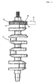
- crank shaft 1 used for an in-line four-cylinder internal combustion engine.
- a rotational torque of the crank shaft 1 is transmitted to a driven gear 4 through a compound gear 3.
- the compound gear 3 is provided on a crank arm 2 formed at one end of the crank shaft 1 and it includes a backlash eliminating mechanism (not shown).
- the compound gear 3 is composed of a main gear 5 serving as the crank arm 2, and a sub-gear 6 fitted around the crank shaft 1 coaxially with the main gear 5 in such a manner as to be brought in contact with the main gear 5.
- the sub-gear 6 is a gear produced by plastic working. Referring to Fig. 2, the sub-gear 6 is formed into an annular shape having a fitting hole 7 at a central area and having, around the fitting hole 7, a plurality of rectangular windows 8 spaced at equal intervals along the circumference and a plurality of circular holes 9 spaced at equal intervals along the circumference. A cut-and-raised claw 10 is formed at one edge of each rectangular window 8 in the circumferential direction. The claw 10 functions as one element of a backlash eliminating mechanism. The circular holes 9 are provided for reducing the weight of the sub-gear 6.
- a composition of a steel plate used for the sub-gear 6 is shown in Table 1.
- Chemical Composition (wt%) C Si Mn P S Al Cu Ti Ni Fe 0.002 0.018 0.25 0.014 0.002 0.05 1.24 0.05 0.7 balance
- the above steel plate is produced using a hot strip mill.
- the steel plate is subjected to solution treatment by rapid cooling from a finishing temperature (solution treatment temperature T 1 ) of 910°C to a winding temperature of 300°C.
- the thickness of the steel plate is 3.5 mm.
- the sub-gear 6 is of a type produced by punching, it is produced by steps of punching using a press, bending using a press, machining, and soft nitriding serving as artificial aging, the steps being sequentially performed in this order.
- This step includes a work of punching the above steel plate to form a blank of 110 mm in diameter; a work of punching the blank to form a semi-finished sub-gear including a teeth portion; and a work of punching the semi-finished sub-gear to form a prepared hole for a fitting hole, circular holes 9, and U-shaped slots for cut-and-raised claws, the works being sequentially performed.
- the semi-finished sub-gear is subjected to bending to form cut-and-raised claws 10 and simultaneously form rectangular windows 8.
- the semi-finished sub-gear is subjected to machining to form a fitting hole 7 based on the above prepared hole, followed by shaving for each tooth surface (tip surface and dedendum surface) of the semi-finished sub-gear.
- the semi-finished sub-gear is subjected to soft nitriding serving as artificial aging, to obtain a sub-gear 6.
- the soft nitriding is performed in an atmosphere of NH 3 gas based on N 2 gas at an artificial aging temperature T 2 of 580°C for a treatment time "t" of 2 hr.
- the sub-gear 6 obtained in such a condition is taken as Inventive Example 1.
- another sub-gear 6 is obtained under a condition in which only the treatment time "t" is changed from the above value 2 hr into 3 hr.
- the sub-gear 6 thus obtained is taken as Inventive Example 2.
- a semi-finished sub-gear is similarly formed of a steel plate (thickness: 3.5 mm) made from a soft nitriding steel having a composition of C (0.3 wt%)-Mn (1 wt%)-Cr (1 wt%)-V (0.1 wt%)-B (0.001 wt%)-Fe (balance), followed by soft nitriding, to obtain a sub-gear.
- the treatment condition is the same as that described above except that the treatment time "t" is set at 3 hr.
- the sub-gear thus obtained is taken as Comparative Example 1.
- a semi-finished sub gear is similarly formed of a steel plate (thickness: 3.5 mm) made from an Al-Cr-Mo steel (JIS SACM 645) treated by quenching and tempering, followed by soft nitriding, to obtain a sub-gear.
- the treatment condition is the same as that described above except that the treatment time "t" is set at 3 hr.
- the sub-gear thus obtained is taken as Comparative Example 2.
- a semi-finished sub-gear is similarly formed of a steel plate (thickness: 3.5 mm) made from a carburized steel (JIS SCM415H), followed by carburizing/quenching, to obtain a sub-gear.
- the carburizing/quenching is performed by holding the semi-finished sub-gear in a carburizing atmosphere at 910°C for 1.5 hr and at 840°C for 0.5 hr, and rapid cooling it.
- the sub-gear thus obtained is taken as Comparative Example 3.
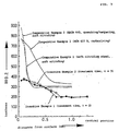
- Fig. 3 is a graph showing a relationship between a distance from the surface and a hardness (Hv 0.2) for each of Inventive Examples 1, 2 and Comparative Examples 1 to 3.
- a depth "d" of a surface hardened layer of each of Inventive Examples 1, 2 is deeper that of each of Comparative Examples 1 to 3; however, a hardness of the surface or its vicinity of each of Inventive Examples 1, 2 is lower than that of each of Comparative Examples 1 to 3.
- Inventive Examples 1, 2 and Comparative Examples 1 to 3 are subjected to completely reversed plane bending test for measuring the bending fatigue strength of a dedendum 11 of each example (sub-gear 6).
- Fig. 4 is a graph showing a relationship between the number N of repetitions of stress and a stress amplitude ⁇ a for each of Inventive Examples 1, 2 and Comparative Examples 1 to 3.
- Table 2 shows the stress amplitude ⁇ a when the number (N) of repetitions of stress reaches 10 7 times for each of Inventive Examples 1, 2 and Comparative Examples 1 to 3.
- stress amplitude ⁇ a (MPa) at N 10 7 (N: number of repetitions of stress)
- Inventive Example 2 686 Comparative Example 1 549 Comparative Example 2 640 Comparative Example 3 647
- each of Inventive Examples 1, 2 is higher in bending fatigue strength than each of Comparative Examples 1 to 3.
- the sub-gear 6 is of a type produced by hot forging, it is produced by steps of hot forging, solution treatment, machining, and soft nitriding serving as artificial aging, the steps being sequentially performed in this order.
- a semi-finished sub-gear similar to that obtained after completion of the above step B, is obtained by works of cutting off a steel piece (thickness: 30 mm) from a round steel bar (diameter: 50 mm) a steel having the composition shown in Table 1, heating the steel piece to a temperature of 950°C, removing scales from the steel piece, stamping the steel piece by a high speed forging press, removing burrs by a crank press, and shaping the steel piece thus stamped by the crank press, the works being sequentially performed in this order.
- the semi-finished sub-gear is subjected to solution treatment by rapidly cooling the semi-finished sub-gear held at 910°C, which is a hot forging ending temperature (solution treatment temperature T 1 ).
- the semi-finished sub-gear is subjected to works similar to those described steps C, D, to obtain a sub-gear 6.
- the treatment time "t" in the step D is set at 3 hr.
- the sub-gear 6 thus obtained exhibits a high bending fatigue strength comparative to those of Inventive Examples 1, 2.
- the present invention provides a gear having a high fatigue strength and a high dimensional accuracy.
- the gear is produced from a steel material which is excellent in plastic workability and machinability and which is capable of being subjected to soft nitriding serving as artificial aging after solution treatment.
- soft nitriding serving as artificial aging after solution treatment.
- artificial aging and soft nitriding step are simultaneously performed. As a result, it is possible to achieve energy saving and reduction in production cost, and hence to provide a relatively inexpensive gear.
- the gear has a sufficiently deep surface hardened layer, and it is aimed at energy saving and reduction in production cost by simultaneously performing artificial aging and soft nitriding.
Landscapes
- Chemical & Material Sciences (AREA)
- Engineering & Computer Science (AREA)
- Materials Engineering (AREA)
- Mechanical Engineering (AREA)
- Metallurgy (AREA)
- Organic Chemistry (AREA)
- Chemical Kinetics & Catalysis (AREA)
- Thermal Sciences (AREA)
- Crystallography & Structural Chemistry (AREA)
- Physics & Mathematics (AREA)
- Heat Treatment Of Articles (AREA)
- Solid-Phase Diffusion Into Metallic Material Surfaces (AREA)
- Gears, Cams (AREA)
Description
- The present invention relates to a high fatigue strength gear.
- Conventionally, there has been known a high fatigue strength gear made from a soft nitriding steel as a low or medium carbon steel containing Al, Cr, and the like specified, for example, under JIS SACM645. However, such a steel cannot achieve a fatigue strength necessary for a gear only by soft nitriding, and thereby it is quenched and tempered for improving an inner hardness (that is, internal strength).
- However, since the soft nitriding is applied to a semi-finished gear after being mechanically worked, the increasing degree of the hardness due to quenching and tempering is limited in consideration of the mechanical workability. As a result, the fatigue strength of the gear, particularly, the bending fatigue strength of the dedendum of the gear cannot be improved as expected. That is, the above gear is inferior in bending fatigue strength to a gear subjected to carburizing.
- JP 3 122 254 A discloses steel plates for motor cars and domestic appliances consisting of, by weight, up to 0.010 % C, up to 1.0 % Si, 0.05-0.5 % Mn, up to 0.1 % P, up to 0.03 % S, 0.20-0.10 % sol. Al, 0.8-1.7 % Cu, 0.02-0.1 % Ti, and the balance Fe; in those steel plates, the strength in the part other than the surface can be increased simultaneously with surface hardening at the time of the nitriding treatment.
- An object of the present invention is to provide a gear having a high fatigue strength and a high dimensional accuracy, which is formed from a specific steel material being excellent in plastic workability and mechanical workability and capable of being subjected to soft nitriding serving as artificial aging after solution treatment.
- The invention is defined by the appended claims.
- To achieve the above object, according to the present invention, there is provided a high fatigue strength gear formed from a steel material by plastic working, the steel material containing C≦0.01 wt%, Si≦1 wt%, 0.05 wt%≦Mn≦0.5 wt%, P≦0.1 wt%, S≦0.03 wt%, 0.02 wt%≦sol. Al≦0.1 wt%, 0.8 wt%≦Cu≦1.7 wt%, and 0.02 wt%≦ Ti≦0.1 wt%, the balance being Fe and inevitable elements, wherein the gear is subjected to soft nitriding serving as artificial aging, wherein aging is performed at a temperature T2 within a range of 550°C ≤ T2 ≤ 600°C, after being subjected to solution treatment, and wherein said gear comprises a hardened surface layer having a depth of from 0.6 mm to 1.0 mm.
- The steel material having the above composition has a metal structure composed of a ferrite single phase, and consequently, it exhibits a desirable plastic workability and mechanical workability substantially comparative to those of a mild steel.
- Since the above steel material exhibits age-hardenability by saturated solution of Cu, the mechanical strength of the gear can be improved by applying artificial aging treatment to the semi-finished gear having been already subjected to solution heat treatment.
- Since the above steel material contains Ti as well as a very low amount of C, it exhibits a desirable soft nitriding characteristic under an artificial aging temperature after solution treatment. In other words, in this steel material, the artificial aging temperature substantially corresponds to the soft nitriding temperature.
- Accordingly, the fatigue strength of the gear can be sufficiently improved without quenching and tempering by applying soft nitriding serving as.artificial aging to the semi-finished gear. Further, since both treatments, soft nitriding and artificial aging, are simultaneously performed, it is possible to achieve energy saving and reduction in production cost.
- The depth "d" of the hardened surface layer (which means the total nitrided layer, the same shall apply hereinafter) is 0.6 mm to 1.0 mm. If the depth "d" is more than 1.0 mm, the gear may be embrittled.
- Since the soft nitriding is performed at a relatively low temperature, the strain of the gear generated by heat treatment is small. Accordingly, by shaving the gear prior to soft nitriding, the gear keeps a high dimensional accuracy after soft nitriding. Thus, it is possible to eliminate the finish work of a tooth flank of the gear by polishing, which is required for the gear having been carburized.
- The effect of each chemical component of the above steel material and the reason why the content thereof is limited are as follows:
- This element contained in the above steel material is effective to form a ferrite single, phase and hence to ensure a high ductility. To make deeper the surface hardened layer by soft nitriding, the content of C is desired to be made as small as possible. When the carbon content is more than 0.01 wt%, the ductility of the steel material is reduced, and the surface hardened layer is made narrower.
- Si is an element of improving the strength of the steel material. The content of Si is adjusted in accordance with the strength required for the steel material. When the content of Si is more than 1 wt%, the ductility of the steel material is reduced, and thereby the plastic workability of the steel material becomes lower.
- Mn is an element of improving the strength of the steel material, like Si. The content of Mn is adjusted in accordance with the strength required for the steel material. When the content of Mn is more than 0.5 wt%, the ductility of the steel material is reduced, and thereby the plastic workability becomes lower. When it is less than 0.05 wt%, the additional effect is lost and also surface defects tend to be generated on the surface of the steel material.
- P is an element of improving the strength of the steel material, line Mn. The content of P is adjusted in accordance with the strength required for the steel material. When the content of P is more than 0.1 wt%, there is a possibility that cracks are generated by secondary working.
- The content of S is desired to be smaller for enhancing the ductility of the steel material. When the content of S is more than 0.03 wt%, the ductility of the steel material is significantly reduced.
- Al is an element having an effect of enhancing the soft nitriding characteristic of the steel material. When the content of Al is more than 0.1 wt%, the plastic workability and mechanical workability of the steel material are reduced. When it is less than 0.02 wt%, the additional effect is lost.
- Cu gives an age-hardenability to the steel material as described above. When the content of Cu is more than 1.7 wt%, the surface quality of the steel material is degraded. When it is less than 0.8 wt%, the additional effect is lost.
- Ti is an element of giving a soft nitriding characteristic to the steel material containing a very low amount of carbon. Specifically, Ti forms a fine complex nitride together with Fe and makes deep a surface hardened layer. When the content of Ti is more than 0.1 wt%, the surface hardened layer becomes excessively deep, making brittle the steel material. When it is less than 0.02 wt%, the additional effect is lost.
- The above steel material may contain Ni in an amount of 0.15 wt% to 0.7 wt%, in addition to the above elements. Ni has an effect of enhancing the surface quality of the steel material and preventing thermal embrittlement.
- In the case where a steel plate is used as the above steel material, it is often used as hot-rolled. In this case, the solution treatment for the steel plate is performed by rapidly cooling the steel plate from a finishing temperature to a winding temperature at the rolling step. In the case where a bar steel is used as the above steel material, it can be subjected to solution treatment at the final stage of the hot-rolling. However, if the bar steel is hot-forged, it may be subjected to solution treatment by rapid cooling after completion of the hot forging or rapid cooling after re-heating serving as adjustment of crystal grain sizes.
- The solution treatment temperature T1, which is the above finishing temperature of hot rolling or the hot-forging ending temperature, may be set at a value of 780°C to 1050°C. When the temperature is less than 780°C, it is difficult to achieve saturated solution of Cu. When it is more than 1050°C, crystal grains are coarsened, leading to reduction in strength and toughness.
- The artificial aging temperature T2 for the steel material may be set at a value of 550°C to 600°C. When the temperature is more than 600°C, there occurs over-aging, which leads to reduction in internal hardness, thereby making it impossible to sufficiently improve the fatigue strength. When it is less than 550°C, it is impossible to perform the artificial aging and soft nitriding. The treatment time "t" is desirable to be set at a value of 2 hr to 4 hr. When the treatment time is less than 2 hr, the depth "d" of the surface hardened layer is less than 0.6 mm. When it is more than 4 hr, the depth "d" exceeds the upper limit d = 1.0 mm.
- Referring to Fig. 1, there is shown a
crank shaft 1 used for an in-line four-cylinder internal combustion engine. A rotational torque of thecrank shaft 1 is transmitted to a driven gear 4 through acompound gear 3. Thecompound gear 3 is provided on acrank arm 2 formed at one end of thecrank shaft 1 and it includes a backlash eliminating mechanism (not shown). - The
compound gear 3 is composed of a main gear 5 serving as thecrank arm 2, and a sub-gear 6 fitted around thecrank shaft 1 coaxially with the main gear 5 in such a manner as to be brought in contact with the main gear 5. - The
sub-gear 6 is a gear produced by plastic working. Referring to Fig. 2, thesub-gear 6 is formed into an annular shape having a fitting hole 7 at a central area and having, around the fitting hole 7, a plurality of rectangular windows 8 spaced at equal intervals along the circumference and a plurality ofcircular holes 9 spaced at equal intervals along the circumference. A cut-and-raisedclaw 10 is formed at one edge of each rectangular window 8 in the circumferential direction. Theclaw 10 functions as one element of a backlash eliminating mechanism. Thecircular holes 9 are provided for reducing the weight of thesub-gear 6. - The
sub-gear 6, which has the fitting hole 7, rectangular windows 8, andcircular holes 9 as described above, requires a high fatigue strength. - A composition of a steel plate used for the
sub-gear 6 is shown in Table 1.Chemical Composition (wt%) C Si Mn P S Al Cu Ti Ni Fe 0.002 0.018 0.25 0.014 0.002 0.05 1.24 0.05 0.7 balance - The above steel plate is produced using a hot strip mill. The steel plate is subjected to solution treatment by rapid cooling from a finishing temperature (solution treatment temperature T1) of 910°C to a winding temperature of 300°C. The thickness of the steel plate is 3.5 mm.
- In the case where the
sub-gear 6 is of a type produced by punching, it is produced by steps of punching using a press, bending using a press, machining, and soft nitriding serving as artificial aging, the steps being sequentially performed in this order. - The above steps will be described in detail below.
- This step includes a work of punching the above steel plate to form a blank of 110 mm in diameter; a work of punching the blank to form a semi-finished sub-gear including a teeth portion; and a work of punching the semi-finished sub-gear to form a prepared hole for a fitting hole,
circular holes 9, and U-shaped slots for cut-and-raised claws, the works being sequentially performed. - The semi-finished sub-gear is subjected to bending to form cut-and-raised
claws 10 and simultaneously form rectangular windows 8. - The semi-finished sub-gear is subjected to machining to form a fitting hole 7 based on the above prepared hole, followed by shaving for each tooth surface (tip surface and dedendum surface) of the semi-finished sub-gear.
- The semi-finished sub-gear is subjected to soft nitriding serving as artificial aging, to obtain a
sub-gear 6. The soft nitriding is performed in an atmosphere of NH3 gas based on N2 gas at an artificial aging temperature T2 of 580°C for a treatment time "t" of 2 hr. The sub-gear 6 obtained in such a condition is taken as Inventive Example 1. Next, anothersub-gear 6 is obtained under a condition in which only the treatment time "t" is changed from theabove value 2 hr into 3 hr. The sub-gear 6 thus obtained is taken as Inventive Example 2. - The above sub-gears (Inventive Examples 1, 2) are compared with the following comparative examples. A semi-finished sub-gear is similarly formed of a steel plate (thickness: 3.5 mm) made from a soft nitriding steel having a composition of C (0.3 wt%)-Mn (1 wt%)-Cr (1 wt%)-V (0.1 wt%)-B (0.001 wt%)-Fe (balance), followed by soft nitriding, to obtain a sub-gear. The treatment condition is the same as that described above except that the treatment time "t" is set at 3 hr. The sub-gear thus obtained is taken as Comparative Example 1.
- A semi-finished sub gear is similarly formed of a steel plate (thickness: 3.5 mm) made from an Al-Cr-Mo steel (JIS SACM 645) treated by quenching and tempering, followed by soft nitriding, to obtain a sub-gear. The treatment condition is the same as that described above except that the treatment time "t" is set at 3 hr. The sub-gear thus obtained is taken as Comparative Example 2.
- A semi-finished sub-gear is similarly formed of a steel plate (thickness: 3.5 mm) made from a carburized steel (JIS SCM415H), followed by carburizing/quenching, to obtain a sub-gear. The carburizing/quenching is performed by holding the semi-finished sub-gear in a carburizing atmosphere at 910°C for 1.5 hr and at 840°C for 0.5 hr, and rapid cooling it. The sub-gear thus obtained is taken as Comparative Example 3.
- Fig. 3 is a graph showing a relationship between a distance from the surface and a hardness (Hv 0.2) for each of Inventive Examples 1, 2 and Comparative Examples 1 to 3. As is apparent from Fig. 3, a depth "d" of a surface hardened layer of each of Inventive Examples 1, 2 is deeper that of each of Comparative Examples 1 to 3; however, a hardness of the surface or its vicinity of each of Inventive Examples 1, 2 is lower than that of each of Comparative Examples 1 to 3.
- Inventive Examples 1, 2 and Comparative Examples 1 to 3 are subjected to completely reversed plane bending test for measuring the bending fatigue strength of a dedendum 11 of each example (sub-gear 6).
- Fig. 4 is a graph showing a relationship between the number N of repetitions of stress and a stress amplitude σa for each of Inventive Examples 1, 2 and Comparative Examples 1 to 3. Table 2 shows the stress amplitude σa when the number (N) of repetitions of stress reaches 107 times for each of Inventive Examples 1, 2 and Comparative Examples 1 to 3.
stress amplitude σa (MPa) at N = 107 (N: number of repetitions of stress) Inventive Example 1 675 Inventive Example 2 686 Comparative Example 1 549 Comparative Example 2 640 Comparative Example 3 647 - As is apparent from Fig. 4 and Table 2, each of Inventive Examples 1, 2 is higher in bending fatigue strength than each of Comparative Examples 1 to 3.
- In the case where the
sub-gear 6 is of a type produced by hot forging, it is produced by steps of hot forging, solution treatment, machining, and soft nitriding serving as artificial aging, the steps being sequentially performed in this order. - The steps will be described in detail below.
- A semi-finished sub-gear, similar to that obtained after completion of the above step B, is obtained by works of cutting off a steel piece (thickness: 30 mm) from a round steel bar (diameter: 50 mm) a steel having the composition shown in Table 1, heating the steel piece to a temperature of 950°C, removing scales from the steel piece, stamping the steel piece by a high speed forging press, removing burrs by a crank press, and shaping the steel piece thus stamped by the crank press, the works being sequentially performed in this order.
- The semi-finished sub-gear is subjected to solution treatment by rapidly cooling the semi-finished sub-gear held at 910°C, which is a hot forging ending temperature (solution treatment temperature T1).
- Subsequently, the semi-finished sub-gear is subjected to works similar to those described steps C, D, to obtain a
sub-gear 6. In addition, the treatment time "t" in the step D is set at 3 hr. The sub-gear 6 thus obtained exhibits a high bending fatigue strength comparative to those of Inventive Examples 1, 2. - The present invention provides a gear having a high fatigue strength and a high dimensional accuracy. The gear is produced from a steel material which is excellent in plastic workability and machinability and which is capable of being subjected to soft nitriding serving as artificial aging after solution treatment. In the steps of the producing the gear, artificial aging and soft nitriding step are simultaneously performed. As a result, it is possible to achieve energy saving and reduction in production cost, and hence to provide a relatively inexpensive gear.
-
- Fig. 1: A front view of a crank shaft including a compound gear.
- Fig. 2: A perspective view of a sub-gear.
- Fig. 3: A graph showing a relationship between a distance from the surface and a hardness (Hv 0.2) for each sub-gear.
- Fig. 4: A graph showing a relationship between the number N of repetitions of stress and a stress amplitude σa.
-
-
- 1: crank shaft, 3: compound gear, 5: main gear, 6: sub-gear
-
- To provide a relatively inexpensive gear having a high fatigue strength there is provided a gear according to the claims. The gear has a sufficiently deep surface hardened layer, and it is aimed at energy saving and reduction in production cost by simultaneously performing artificial aging and soft nitriding.
Claims (4)
- A high fatigue strength gear formed from a steel material by plastic working, said steel material containing C≦0.01 wt%, Si≦1 wt%, 0.05 wt%≦Mn≦0.5 wt%, P ≦0.1 wt%, S≦0.03 wt%, 0.02 wt%≦sol. Al≦0.1 wt%, 0.8 wt% ≦Cu≦1.7 wt%, and 0.02 wt%≦Ti≦0.1 wt%, the balance being Fe and inevitable elements, wherein said gear is subjected to soft nitriding serving as artificial aging, wherein aging is performed at a temperature T2 within a range of 550°C ≤ T2 ≤ 600°C, after being subjected to solution treatment and wherein said gear comprises a hardened surface layer having a depth of from 0.6 mm to 1.0 mm.
- A high fatigue strength gear formed from a steel material by plastic working, said steel material containing C≦0.01 wt%, Si≦1 wt%, 0.05 wt%≦Mn≦0.5 wt%, P ≦0.1 wt%, S≦0.03 wt%, 0.02 wt%≦sol. Al≦0.1 wt%, 0.8 wt% ≦Cu≦1.7 wt%, 0.02 wt%≦Ti≦0.1 wt%, and 0.15 wt%≦Ni≦0.7 wt%, the balance being Fe and inevitable elements, wherein said gear is subjected to soft nitriding serving as artificial aging, wherein aging is performed at a temperature T2 within a range of 550°C ≤ T2 ≤ 600°C, after being subjected to solution treatment and wherein said gear comprises a hardened surface layer having a depth of from 0.6 mm to 1.0 mm.
- A high fatigue strength gear according to any one of claims 1 to 2, wherein said gear is formed from said steel material by punching.
- A high fatigue strength gear according to any one of claims 1 to 3, wherein said gear is formed from said steel material by hot-forging.
Applications Claiming Priority (3)
| Application Number | Priority Date | Filing Date | Title |
|---|---|---|---|
| JP18369496 | 1996-07-12 | ||
| JP8183694A JPH1030707A (en) | 1996-07-12 | 1996-07-12 | High fatigue strength gear |
| JP183694/96 | 1996-07-12 |
Publications (2)
| Publication Number | Publication Date |
|---|---|
| EP0818546A1 EP0818546A1 (en) | 1998-01-14 |
| EP0818546B1 true EP0818546B1 (en) | 2003-05-07 |
Family
ID=16140314
Family Applications (1)
| Application Number | Title | Priority Date | Filing Date |
|---|---|---|---|
| EP97111662A Expired - Lifetime EP0818546B1 (en) | 1996-07-12 | 1997-07-09 | High fatigue strength gear |
Country Status (6)
| Country | Link |
|---|---|
| US (1) | US6033496A (en) |
| EP (1) | EP0818546B1 (en) |
| JP (1) | JPH1030707A (en) |
| CN (1) | CN1073217C (en) |
| DE (1) | DE69721645T2 (en) |
| ES (1) | ES2193301T3 (en) |
Families Citing this family (11)
| Publication number | Priority date | Publication date | Assignee | Title |
|---|---|---|---|---|
| JP4411751B2 (en) * | 2000-06-28 | 2010-02-10 | アイシン精機株式会社 | Flat member with gear part |
| AU2003281863A1 (en) * | 2002-07-29 | 2004-02-23 | Koninklijke Philips Electronics N.V. | Plasma-nitriding of maraging steel, shaver cap for an electric shaver, cutting device made out of such steel and an electric shaver |
| WO2005024274A1 (en) * | 2003-09-02 | 2005-03-17 | Namiki Seimitsu Houseki Kabushiki Kaisha | Precision gear, its gear mechanism and production method of precision gear |
| CA2591093A1 (en) * | 2004-12-09 | 2006-06-15 | United Technologies Corporation | Method and process for thermochemical treatment of high-strength, high-toughness alloys |
| JP4500708B2 (en) * | 2005-02-25 | 2010-07-14 | 住友金属工業株式会社 | Non-tempered steel nitrocarburized parts |
| JP4819201B2 (en) * | 2010-03-16 | 2011-11-24 | 新日本製鐵株式会社 | Soft nitriding steel, soft nitriding steel component and manufacturing method thereof |
| JP2012143821A (en) * | 2011-01-07 | 2012-08-02 | Aisin Seiki Co Ltd | Method for manufacturing gear |
| CN103334076B (en) * | 2013-06-21 | 2015-11-18 | 浙江太阳股份有限公司 | A kind of crankshaft nitriding process for cooling |
| WO2015073098A2 (en) * | 2013-08-27 | 2015-05-21 | University Of Virginia Patent Foundation | Three-dimensional space frames assembled from component pieces and methods for making the same |
| CN106514165A (en) * | 2016-12-15 | 2017-03-22 | 贵州群建精密机械有限公司 | Glow-ion nitriding treatment method for gear made of 05Cr17Ni4Cu4Nb material |
| CN110434324A (en) * | 2019-07-10 | 2019-11-12 | 西安交通大学 | A kind of high-performance powder forging alloy material and preparation method thereof |
Family Cites Families (9)
| Publication number | Priority date | Publication date | Assignee | Title |
|---|---|---|---|---|
| US3856514A (en) * | 1970-10-19 | 1974-12-24 | Daido Steel Co Ltd | Cold workable and age-hardenable steel |
| US3837845A (en) * | 1972-03-27 | 1974-09-24 | Int Nickel Co | Oxide coated ferrous metal powder |
| CA1085190A (en) * | 1977-07-13 | 1980-09-09 | Thoni V. Philip | Case-hardening alloy steel and case-hardened article made therefrom |
| US4225365A (en) * | 1978-11-15 | 1980-09-30 | Caterpillar Tractor Co. | Lower bainite alloy steel article and method of making same |
| US4318739A (en) * | 1979-06-05 | 1982-03-09 | A. Finkl & Sons Co. | Steel having improved surface and reduction of area transverse properties, and method of manufacture thereof |
| CN85108118B (en) * | 1985-11-01 | 1987-11-04 | 鞍山钢铁公司 | Low alloy atmospheric corrosion resistant steel |
| JPH0747797B2 (en) * | 1989-03-10 | 1995-05-24 | 川崎製鉄株式会社 | Steel plate for enamel having excellent scabbing resistance, bubble resistance, black spot defect resistance and press formability, and method for producing the same |
| JP2742951B2 (en) * | 1989-10-06 | 1998-04-22 | 新日本製鐵株式会社 | Hot rolled steel sheet for nitriding |
| JPH0718379A (en) * | 1993-06-30 | 1995-01-20 | Aichi Steel Works Ltd | Steel for machine structure excellent in seizing resistance and fatigue strength |
-
1996
- 1996-07-12 JP JP8183694A patent/JPH1030707A/en active Pending
-
1997
- 1997-07-09 ES ES97111662T patent/ES2193301T3/en not_active Expired - Lifetime
- 1997-07-09 EP EP97111662A patent/EP0818546B1/en not_active Expired - Lifetime
- 1997-07-09 DE DE69721645T patent/DE69721645T2/en not_active Expired - Fee Related
- 1997-07-11 CN CN97114627A patent/CN1073217C/en not_active Expired - Fee Related
- 1997-07-14 US US08/892,096 patent/US6033496A/en not_active Expired - Fee Related
Also Published As
| Publication number | Publication date |
|---|---|
| CN1073217C (en) | 2001-10-17 |
| DE69721645T2 (en) | 2003-11-27 |
| EP0818546A1 (en) | 1998-01-14 |
| DE69721645D1 (en) | 2003-06-12 |
| JPH1030707A (en) | 1998-02-03 |
| CN1172918A (en) | 1998-02-11 |
| ES2193301T3 (en) | 2003-11-01 |
| US6033496A (en) | 2000-03-07 |
Similar Documents
| Publication | Publication Date | Title |
|---|---|---|
| JPH06323399A (en) | Automotive gear and manufacturing method thereof | |
| JP3995904B2 (en) | Method for producing inner ring for constant velocity joint excellent in workability and strength | |
| EP3088550A1 (en) | Carburized-steel-component production method, and carburized steel component | |
| US6059898A (en) | Induction hardening of heat treated gear teeth | |
| US6033496A (en) | High fatigue strength gear | |
| JPS6043431B2 (en) | Manufacturing method of nitrided machine parts for light loads | |
| JPH0971841A (en) | Steel for soft-nitriding | |
| JPH09279295A (en) | Steel for soft nitriding with excellent cold forgeability | |
| JP2549039B2 (en) | Carbonitriding heat treatment method for high strength gears with small strain | |
| JPH10226817A (en) | Method of manufacturing steel for nitrocarburizing and nitrocarburized parts using the steel | |
| JP3551573B2 (en) | Steel for carburized gear with excellent gear cutting | |
| JPH0565592A (en) | High fatigue strength steel for structural purpose and steel member made of the same | |
| JPH09241821A (en) | Carburized gear | |
| JPH0570924A (en) | Method for carburizing heat treatment of high strength gear small in strain and the gear | |
| JP3623313B2 (en) | Carburized gear parts | |
| JPH0535203B2 (en) | ||
| JP3240627B2 (en) | Manufacturing method of constant velocity joint parts | |
| JPH1025539A (en) | High fatigue strength press-formed parts | |
| US6391124B1 (en) | Non-heat treated, soft-nitrided steel parts | |
| JP7263796B2 (en) | RING GEAR FOR AUTOMOBILE TRANSMISSION AND MANUFACTURING METHOD THEREOF | |
| JP3319684B2 (en) | Steel material for carburized bevel gear, high toughness carburized bevel gear and method of manufacturing the same | |
| JPH09279296A (en) | Steel for soft nitriding with excellent cold forgeability | |
| JP3109146B2 (en) | Manufacturing method of low strain high strength member | |
| US20200370159A1 (en) | Steel material for cvt sheave, cvt sheave, and method for manufacturing cvt sheave | |
| JP4832790B2 (en) | Steel member surface treatment method and steel member |
Legal Events
| Date | Code | Title | Description |
|---|---|---|---|
| PUAI | Public reference made under article 153(3) epc to a published international application that has entered the european phase |
Free format text: ORIGINAL CODE: 0009012 |
|
| AK | Designated contracting states |
Kind code of ref document: A1 Designated state(s): DE ES IT |
|
| 17P | Request for examination filed |
Effective date: 19980226 |
|
| AKX | Designation fees paid |
Free format text: DE ES IT |
|
| RBV | Designated contracting states (corrected) |
Designated state(s): DE ES IT |
|
| 17Q | First examination report despatched |
Effective date: 20000331 |
|
| GRAH | Despatch of communication of intention to grant a patent |
Free format text: ORIGINAL CODE: EPIDOS IGRA |
|
| GRAH | Despatch of communication of intention to grant a patent |
Free format text: ORIGINAL CODE: EPIDOS IGRA |
|
| GRAA | (expected) grant |
Free format text: ORIGINAL CODE: 0009210 |
|
| AK | Designated contracting states |
Designated state(s): DE ES IT |
|
| REF | Corresponds to: |
Ref document number: 69721645 Country of ref document: DE Date of ref document: 20030612 Kind code of ref document: P |
|
| REG | Reference to a national code |
Ref country code: ES Ref legal event code: FG2A Ref document number: 2193301 Country of ref document: ES Kind code of ref document: T3 |
|
| PLBE | No opposition filed within time limit |
Free format text: ORIGINAL CODE: 0009261 |
|
| STAA | Information on the status of an ep patent application or granted ep patent |
Free format text: STATUS: NO OPPOSITION FILED WITHIN TIME LIMIT |
|
| 26N | No opposition filed |
Effective date: 20040210 |
|
| PGFP | Annual fee paid to national office [announced via postgrant information from national office to epo] |
Ref country code: DE Payment date: 20040615 Year of fee payment: 8 |
|
| PGFP | Annual fee paid to national office [announced via postgrant information from national office to epo] |
Ref country code: ES Payment date: 20040616 Year of fee payment: 8 |
|
| PG25 | Lapsed in a contracting state [announced via postgrant information from national office to epo] |
Ref country code: IT Free format text: LAPSE BECAUSE OF NON-PAYMENT OF DUE FEES Effective date: 20050709 |
|
| PG25 | Lapsed in a contracting state [announced via postgrant information from national office to epo] |
Ref country code: ES Free format text: LAPSE BECAUSE OF NON-PAYMENT OF DUE FEES Effective date: 20050711 |
|
| PG25 | Lapsed in a contracting state [announced via postgrant information from national office to epo] |
Ref country code: DE Free format text: LAPSE BECAUSE OF NON-PAYMENT OF DUE FEES Effective date: 20060201 |
|
| REG | Reference to a national code |
Ref country code: ES Ref legal event code: FD2A Effective date: 20050711 |