EP0818409A1 - Method in winding of a paper web and a winding device - Google Patents
Method in winding of a paper web and a winding device Download PDFInfo
- Publication number
- EP0818409A1 EP0818409A1 EP97660064A EP97660064A EP0818409A1 EP 0818409 A1 EP0818409 A1 EP 0818409A1 EP 97660064 A EP97660064 A EP 97660064A EP 97660064 A EP97660064 A EP 97660064A EP 0818409 A1 EP0818409 A1 EP 0818409A1
- Authority
- EP
- European Patent Office
- Prior art keywords
- winding
- component webs
- component
- slitter
- webs
- Prior art date
- Legal status (The legal status is an assumption and is not a legal conclusion. Google has not performed a legal analysis and makes no representation as to the accuracy of the status listed.)
- Granted
Links
- 238000004804 winding Methods 0.000 title claims abstract description 78
- 238000000034 method Methods 0.000 title claims abstract description 16
- 238000000926 separation method Methods 0.000 claims description 2
- 239000000853 adhesive Substances 0.000 description 2
- 230000001070 adhesive effect Effects 0.000 description 2
- 239000002390 adhesive tape Substances 0.000 description 2
- 230000000694 effects Effects 0.000 description 2
- 238000007664 blowing Methods 0.000 description 1
- 230000002349 favourable effect Effects 0.000 description 1
- 238000012986 modification Methods 0.000 description 1
- 230000004048 modification Effects 0.000 description 1
Images


Classifications
-
- B—PERFORMING OPERATIONS; TRANSPORTING
- B65—CONVEYING; PACKING; STORING; HANDLING THIN OR FILAMENTARY MATERIAL
- B65H—HANDLING THIN OR FILAMENTARY MATERIAL, e.g. SHEETS, WEBS, CABLES
- B65H19/00—Changing the web roll
- B65H19/22—Changing the web roll in winding mechanisms or in connection with winding operations
- B65H19/28—Attaching the leading end of the web to the replacement web-roll core or spindle
-
- B—PERFORMING OPERATIONS; TRANSPORTING
- B65—CONVEYING; PACKING; STORING; HANDLING THIN OR FILAMENTARY MATERIAL
- B65H—HANDLING THIN OR FILAMENTARY MATERIAL, e.g. SHEETS, WEBS, CABLES
- B65H35/00—Delivering articles from cutting or line-perforating machines; Article or web delivery apparatus incorporating cutting or line-perforating devices, e.g. adhesive tape dispensers
- B65H35/04—Delivering articles from cutting or line-perforating machines; Article or web delivery apparatus incorporating cutting or line-perforating devices, e.g. adhesive tape dispensers from or with transverse cutters or perforators
- B65H35/06—Delivering articles from cutting or line-perforating machines; Article or web delivery apparatus incorporating cutting or line-perforating devices, e.g. adhesive tape dispensers from or with transverse cutters or perforators from or with blade, e.g. shear-blade, cutters or perforators
-
- B—PERFORMING OPERATIONS; TRANSPORTING
- B65—CONVEYING; PACKING; STORING; HANDLING THIN OR FILAMENTARY MATERIAL
- B65H—HANDLING THIN OR FILAMENTARY MATERIAL, e.g. SHEETS, WEBS, CABLES
- B65H18/00—Winding webs
- B65H18/08—Web-winding mechanisms
-
- B—PERFORMING OPERATIONS; TRANSPORTING
- B65—CONVEYING; PACKING; STORING; HANDLING THIN OR FILAMENTARY MATERIAL
- B65H—HANDLING THIN OR FILAMENTARY MATERIAL, e.g. SHEETS, WEBS, CABLES
- B65H23/00—Registering, tensioning, smoothing or guiding webs
- B65H23/04—Registering, tensioning, smoothing or guiding webs longitudinally
- B65H23/26—Registering, tensioning, smoothing or guiding webs longitudinally by transverse stationary or adjustable bars or rollers
-
- B—PERFORMING OPERATIONS; TRANSPORTING
- B65—CONVEYING; PACKING; STORING; HANDLING THIN OR FILAMENTARY MATERIAL
- B65H—HANDLING THIN OR FILAMENTARY MATERIAL, e.g. SHEETS, WEBS, CABLES
- B65H35/00—Delivering articles from cutting or line-perforating machines; Article or web delivery apparatus incorporating cutting or line-perforating devices, e.g. adhesive tape dispensers
- B65H35/02—Delivering articles from cutting or line-perforating machines; Article or web delivery apparatus incorporating cutting or line-perforating devices, e.g. adhesive tape dispensers from or with longitudinal slitters or perforators
-
- B—PERFORMING OPERATIONS; TRANSPORTING
- B65—CONVEYING; PACKING; STORING; HANDLING THIN OR FILAMENTARY MATERIAL
- B65H—HANDLING THIN OR FILAMENTARY MATERIAL, e.g. SHEETS, WEBS, CABLES
- B65H2301/00—Handling processes for sheets or webs
- B65H2301/40—Type of handling process
- B65H2301/41—Winding, unwinding
- B65H2301/414—Winding
- B65H2301/41419—Starting winding process
- B65H2301/41426—Starting winding process involving suction means, e.g. core with vacuum supply
-
- B—PERFORMING OPERATIONS; TRANSPORTING
- B65—CONVEYING; PACKING; STORING; HANDLING THIN OR FILAMENTARY MATERIAL
- B65H—HANDLING THIN OR FILAMENTARY MATERIAL, e.g. SHEETS, WEBS, CABLES
- B65H2301/00—Handling processes for sheets or webs
- B65H2301/40—Type of handling process
- B65H2301/41—Winding, unwinding
- B65H2301/414—Winding
- B65H2301/41419—Starting winding process
- B65H2301/41427—Starting winding process involving arrangements for securing leading edge to core, e.g. adhesive tape
-
- B—PERFORMING OPERATIONS; TRANSPORTING
- B65—CONVEYING; PACKING; STORING; HANDLING THIN OR FILAMENTARY MATERIAL
- B65H—HANDLING THIN OR FILAMENTARY MATERIAL, e.g. SHEETS, WEBS, CABLES
- B65H2301/00—Handling processes for sheets or webs
- B65H2301/40—Type of handling process
- B65H2301/41—Winding, unwinding
- B65H2301/414—Winding
- B65H2301/4148—Winding slitting
- B65H2301/41486—Winding slitting winding on two or more winding shafts simultaneously
-
- B—PERFORMING OPERATIONS; TRANSPORTING
- B65—CONVEYING; PACKING; STORING; HANDLING THIN OR FILAMENTARY MATERIAL
- B65H—HANDLING THIN OR FILAMENTARY MATERIAL, e.g. SHEETS, WEBS, CABLES
- B65H2301/00—Handling processes for sheets or webs
- B65H2301/50—Auxiliary process performed during handling process
- B65H2301/51—Modifying a characteristic of handled material
- B65H2301/513—Modifying electric properties
- B65H2301/5133—Removing electrostatic charge
-
- B—PERFORMING OPERATIONS; TRANSPORTING
- B65—CONVEYING; PACKING; STORING; HANDLING THIN OR FILAMENTARY MATERIAL
- B65H—HANDLING THIN OR FILAMENTARY MATERIAL, e.g. SHEETS, WEBS, CABLES
- B65H2301/00—Handling processes for sheets or webs
- B65H2301/50—Auxiliary process performed during handling process
- B65H2301/51—Modifying a characteristic of handled material
- B65H2301/515—Cutting handled material
- B65H2301/5151—Cutting handled material transversally to feeding direction
-
- B—PERFORMING OPERATIONS; TRANSPORTING
- B65—CONVEYING; PACKING; STORING; HANDLING THIN OR FILAMENTARY MATERIAL
- B65H—HANDLING THIN OR FILAMENTARY MATERIAL, e.g. SHEETS, WEBS, CABLES
- B65H2301/00—Handling processes for sheets or webs
- B65H2301/50—Auxiliary process performed during handling process
- B65H2301/51—Modifying a characteristic of handled material
- B65H2301/515—Cutting handled material
- B65H2301/5153—Details of cutting means
- B65H2301/51532—Blade cutter, e.g. single blade cutter
- B65H2301/515326—Multiple blade cutter
-
- B—PERFORMING OPERATIONS; TRANSPORTING
- B65—CONVEYING; PACKING; STORING; HANDLING THIN OR FILAMENTARY MATERIAL
- B65H—HANDLING THIN OR FILAMENTARY MATERIAL, e.g. SHEETS, WEBS, CABLES
- B65H2301/00—Handling processes for sheets or webs
- B65H2301/50—Auxiliary process performed during handling process
- B65H2301/51—Modifying a characteristic of handled material
- B65H2301/515—Cutting handled material
- B65H2301/5155—Cutting handled material longitudinally
-
- B—PERFORMING OPERATIONS; TRANSPORTING
- B65—CONVEYING; PACKING; STORING; HANDLING THIN OR FILAMENTARY MATERIAL
- B65H—HANDLING THIN OR FILAMENTARY MATERIAL, e.g. SHEETS, WEBS, CABLES
- B65H2301/00—Handling processes for sheets or webs
- B65H2301/50—Auxiliary process performed during handling process
- B65H2301/52—Auxiliary process performed during handling process for starting
- B65H2301/522—Threading web into machine
Definitions
- the invention concerns a method as defined in the preamble of claim 1.
- the invention also concerns a winding device as defined in the preamble of claim 5.
- the invention is related to an arrangement in winding of a paper web, in which a paper web, which has been brought as of full width to the slitter-winder, is slit into narrower component webs, which are further wound into component rolls.
- the invention is in particular related to a slitter-winder of the bottom draw centre-drive winder type, in which a web of full width, i.e. of the width of the paper machine, is slit into narrower component webs in the longitudinal direction.
- the invention is, however, also suitable for use in connection with slitter-winders of other types.
- a reel slitter in which a reel slitter is described, whose function is to slit a web of paper-machine width in the longitudinal direction in a slitting or cutting station.
- a pull-in bar is used, which can be passed through the machine by means of a chain and to which the initial end of the web can be attached.
- This prior-art reel slitter comprises two support drums, on whose support the webs are wound.
- the pull-in device provided with a pull-in bar feeds the component webs onto a support drum.
- a transfer device which receives the non-adjacent component webs after their separation from the pull-in bars, feeds the webs by means of a suction tube onto a second support drum.
- a suction tube has been employed as the grasping element for the component webs, which suction tube is a complicated device and has an unreliable adhesion.
- the cutting off of the ends of the component webs and their possible attaching to the grasping element are difficult to make automatic, so that this solution is primarily suitable for manual operation only.
- the introduction of the component webs onto the winding drums requires running of the whole slitter-winder back and forth, which is slow and difficult.
- the object of the invention is to provide a method and a device in winding of a paper web in which drawbacks of the prior-art solutions stated above do not occur.
- An important object of the invention is to achieve threading of a web of full width into the winding device, which threading operates reliably and during which the work of one person only is required.
- the device in accordance with the invention is characterized in what is stated in the characterizing part of claim 5.
- the threading of the web and the splitting of the web into component webs in a slitter-winder of the bottom draw centre-drive winder type are achieved quickly and reliably.
- the web is unwound from the machine reel just once and, moreover, transfer of the component webs onto the winding drums does not require running of the whole slitter-winder.
- the web is passed through the slitter device, in which the web is slit into component webs, to the cutter device, in which the component webs are cut by means of a cutter blade to suitable lengths.
- a nip has been formed by means of a nip roll, which nip is closed before the cutting and through which nip the component webs run.
- the cutting of the component webs is carried out so that the ends of the component webs extend onto the winding drums to the desired, predetermined points, which are favourable in view of starting the rewinding.
- the running of the web has been stopped for the time between the cutting to specified measure and the starting of the rewinding.
- the webs passing to the first winding station are separated from the component webs passing to the second winding station, in compliance with preset specifications.
- the component webs passing to the first winding station are passed, by means of a threading member tightly tensioned between guides, onto the face of the winding drum in the first winding station, to which drum the web adheres by the effect of the suction present in the winding drum, and the threading member is returned to its intermediate position occupied during running.
- the component webs passing onto the winding drum in the second winding station are raised by means of a second threading member onto the face of the winding drum provided with suction, which drum face holds the web end.
- the roll spools are lowered by means of sockets onto the component webs and the winding is started.
- the start of winding is quick, and a good roll bottom is achieved immediately, because
- the component webs are reliably in correct positions in the cross direction of the machine, i.e. precisely in alignment with the spools.
- the spools are possibly provided with adhesive, double-sided adhesive tape, or with some other, equivalent arrangement in itself known to a person skilled in the art so as to fix the web end to the roll spool.
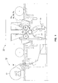
- the winder device comprises an unwind station 10, in which there is a paper reel 12, which is unwound as a paper web W of full width.
- the web W is passed as a bottom draw into the winding device 30, in which the web W is divided into component webs W n and wound into component rolls in a first winding station by means of the winding drum 57 and in a second winding station by means of the winding drum 58.
- the winding device 30 comprises a slitter part 40, in which the web W is slit into component webs W n ;W 1 ,W 2 ,W 3 , etc. in accordance with predefined settings.
- the winding device 30 comprises a cutter device 45, by whose means the web W is cut off in the cross direction.
- the blades 44 slit the web W in accordance with predefined settings into component webs W 1 ,W 2 , W 3 .
- the nip roll 34 to be placed against the guide roll 33 is controlled into the closed position, in which connection the component webs W 1 ,W 2 ,W 3 run through the nip between the guide roll 33 and the nip roll 34 to the cutter device 45, in which the slit component webs W 1 ,W 2 ,W 3 are cut off in the cross direction to such a measure that the component webs W 1 ,W 2 ,W 3 extend to the desired predefined points on the winding drums 57,58.
- the component webs passing onto different winding drums must be cut off to different measures unless the geometries of the guide roll 33 and of the winding drums 57 and 58 have been arranged so that the length of the web from the winding stations to the machine reel of the unwind stand is equal, in which case all the component webs can be cut off to the same measure.
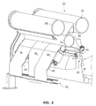
- the cutting off is carried out so that first all the component webs are cut off to a longer measure of component web by means of the blade 451 against the backup blade 450. After the longer component webs (W 1 and W 3 in Fig. 3) have been raised towards their own winding station, the component webs that remain shorter (W 2 in Fig. 3) can be cut off by means of the blade 452 against the backup blade 450.
- a second preferred embodiment of cutting off to different measures consists of a cutter blade 451 or 452 that has been arranged to be displaceable.
- the component webs W 1 ,W 2 ,W 3 are separated in different directions by means of separators 46.
- the component webs W 1 ,W 2 ,W 3 passing to different winding stations are separated by means of the separators 46 in compliance with the setting applicable in each particular case.
- there is a separator 46 of its own by means of which separators the component webs W 1 ,W 2 or W 3 are transferred into a position from which they are passed to the winding station.
- the component webs W 1 ,W 3 have been diverted from the plane of the component web W 2 by means of separators.
- the separators 46 are, for example, articulated bars provided with pneumatic cylinders.
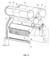
- the threading member 47 has been raised from below through the gap between the separated component webs W 1 ,W 3 and the component web W 2 that remained in its position, in which connection the threading member raises the separated component webs W 1 ,W 3 along with it and carries them onto the winding drum 57.
- the component webs W 1 ,W 3 passing to the first winding station are carried by means of the threading member 47 onto the face of the winding drum 57, to which face the component web W 1 ,W 2 adheres by the effect of the suction in the winding drum 57.
- the guide plate 48 prevents falling down of a component web from the threading member 47 and slackening of said component web on the portion between the guide roll 33 and the winding drum 57, which slackening would change the point to which the ends of the component webs W 1 and W 3 finally extend on the winding drum 57. Finally the threading member 47 is returned to an intermediate position for the time of running operation.
- the component webs W 2 passing to the second winding station are passed by means of the threading member 62 onto the winding drum 58.
- the guide plate 49 permits holding of the component web on its straight track, similarly to the guide plate 48.
- This drum 58 is preferably also provided with suction.
- the guide plates 48 and 49 By means of the guide plates 48 and 49, and in particular by means of the guide plate 49, it is possible to regulate the tension of the component webs during their raising onto the winding drums by varying the position of the guide plate in relation to the threading member.
- the threading members 47 and 62 are bar-like members which extend across the width of the winding device in the cross direction of the component webs W', and said members move along rails 69 provided at both sides of the winding device 30 as tightly tensioned between said rails.
- the threading member 47,62 is, for example, a wire cable or equivalent guided and tightened from its ends.
- the spools are lowered by means of the sockets onto the component webs, and the winding by means of the slitter-winder is started.
- the spools can be provided, for example, with adhesive, double-sided adhesive tape, or with any other arrangements in themselves known to a person skilled in the art, by whose means the web is attached to the spools.
Landscapes
- Replacement Of Web Rolls (AREA)
- Winding Of Webs (AREA)
Abstract
Description
- the ends of the component webs are in the correct positions in relation to the reel spools in the directions both of the axis and of the tangent of the winding drum,
- owing to mechanized cutting, the ends of the component webs are whole and even,
- the guide roll nip, which has been closed by pressing, keeps the major part of the web length tight, in which case, right at the beginning of the winding, the correct winding tension is obtained, and because
- the machine reel that is being unwound does not have to be rotated in order to align the ends of the component webs on the winding drums, in which connection the nip of the guide roll can maintain the tension.
Claims (10)
- A method in winding of a paper web, in which method the paper web (W) is unwound from a paper reel (10), in which method the paper web (W) is slit in a slitter-winder (30) longitudinally into component webs (Wn), which component webs (Wn) are further wound into component rolls, and in which method the paper web (W) is passed through the slitting station (40) of the slitter-winder (30), in which slitting station component webs (Wn) are slit out of the web (W) by means of blades (44), characterized in that the ends of the slit component webs (Wn) are cut off in a cutter device (45) into predetermined measures before the component webs (Wn) are passed into the winding stations.
- A method as claimed in claim 1, characterized in that, in the method, the component webs (Wn) are separated by means of separators (46) to component webs (Wn) passing to different winding stations, and that the component webs (Wn) passing to the first winding station are transferred onto the winding drum (57) of the first winding station by means of a threading member (47), and the component webs (Wn) passing to the second winding station are transferred onto the winding drum (58) of the second winding station by means of a threading member (62).
- A method as claimed in claim 1 or 2, characterized in that, after the slitter part (40), the nip roll (34) that is to be placed against the guide roll (33) is controlled into the closed position, after which the slit component webs (Wn) pass through the nip (N) formed between the guide roll (33) and the nip roll (34).
- A method as claimed in claim 1 or 2, characterized in that, in the method, the component webs (Wn) are made to adhere to the face of the winding drum (57,58) by means of suction.
- A winding device in winding of a paper web or equivalent, comprising an unwind station (10) and a slitter-winder (30), which includes a slitting station (40), a cutter device (45), and the winding stations for component rolls, characterized in that the cutter device (45) of the slitter-winder (30) includes an arrangement for cutting the component webs (Wn) into predetermined measures.
- A device as claimed in claim 5, characterized in that the slitter-winder (30) further includes members (46) for separation of the component webs (Wn), which have been slit from the paper web (W) in the longitudinal direction and which have been cut off after threading by means of the cutter device (45) in the cross direction, and threading members (47;62) for passing the component webs (Wn) onto the respective winding drums (57,58) of the first and the second winding station.
- A device as claimed in claim 5 or 6, characterized in that, after the slitter device (40), the device includes a guide roll (33) and a nip roll (34) to be placed against the guide roll, and the slit and cut-off component webs (Wn) pass through the nip (N) formed by said guide roll and nip roll.
- A device as claimed in claim 5 or 6, characterized in that the winding drums (57,58) are provided with suction so as to make the component webs (Wn) to adhere to the face of the winding drum (57,58).
- A device as claimed in claim 5, characterized in that the cutter device (45) in the slitter-winder (30) comprises two blades (451,452) and a backup blade (450) for cutting off the component webs to different lengths.
- A device as claimed in claim 5, characterized in that the cutter device (45) in the slitter-winder comprises a displaceable cutter blade (451;452).
Applications Claiming Priority (2)
| Application Number | Priority Date | Filing Date | Title |
|---|---|---|---|
| FI962762A FI101371B (en) | 1996-07-05 | 1996-07-05 | Method of rolling paper web and rolling device |
| FI962762 | 1996-07-05 |
Publications (2)
| Publication Number | Publication Date |
|---|---|
| EP0818409A1 true EP0818409A1 (en) | 1998-01-14 |
| EP0818409B1 EP0818409B1 (en) | 2002-05-22 |
Family
ID=8546344
Family Applications (1)
| Application Number | Title | Priority Date | Filing Date |
|---|---|---|---|
| EP97660064A Expired - Lifetime EP0818409B1 (en) | 1996-07-05 | 1997-06-11 | Method in winding of a paper web and a winding device |
Country Status (8)
| Country | Link |
|---|---|
| US (1) | US5782425A (en) |
| EP (1) | EP0818409B1 (en) |
| JP (1) | JP3679226B2 (en) |
| KR (1) | KR100475288B1 (en) |
| AT (1) | ATE217851T1 (en) |
| CA (1) | CA2209962C (en) |
| DE (1) | DE69712675T2 (en) |
| FI (1) | FI101371B (en) |
Cited By (9)
| Publication number | Priority date | Publication date | Assignee | Title |
|---|---|---|---|---|
| WO2002002284A1 (en) * | 2000-07-03 | 2002-01-10 | Metso Paper, Inc. | Method and apparatus in changing the setting of a slitter |
| KR100475288B1 (en) * | 1996-07-05 | 2005-08-29 | 메트소 페이퍼, 인코포레이티드 | Method in winding of a paper web and a winding device |
| EP1174935A3 (en) * | 2000-07-18 | 2006-09-27 | Nisshinbo Industries, Inc. | Slitter for an electrode raw material sheet and the slitting process |
| WO2012056096A1 (en) * | 2010-10-29 | 2012-05-03 | Metso Paper, Inc. | Device for winding of fiber webs, especially of paper and board webs |
| EP2664567A1 (en) | 2012-05-16 | 2013-11-20 | Metso Paper Inc. | Method for web threading in a slitter-winder and a slitter-winder |
| CN103922170A (en) * | 2014-05-03 | 2014-07-16 | 胡齐放 | A strip winding device |
| US9169095B2 (en) | 2012-04-16 | 2015-10-27 | Valmet Technologies, Inc. | Method and device for winding of fiber webs, especially of paper and board webs |
| CN105080219A (en) * | 2014-05-03 | 2015-11-25 | 胡齐放 | Equipment for producing membrane filter material |
| CN105270897A (en) * | 2014-05-05 | 2016-01-27 | 胡齐放 | Production equipment of composite wrapping paper |
Families Citing this family (8)
| Publication number | Priority date | Publication date | Assignee | Title |
|---|---|---|---|---|
| DE19727326A1 (en) * | 1997-06-27 | 1999-01-07 | Voith Sulzer Finishing Gmbh | Roll cutting device |
| DE19729530C2 (en) * | 1997-07-10 | 1999-05-20 | Voith Sulzer Finishing Gmbh | Slitter |
| WO2004041229A1 (en) * | 2002-11-07 | 2004-05-21 | Nippon Zettoc Co.,Ltd. | Base for oral composition and oral composition |
| FI120644B (en) | 2008-04-25 | 2010-01-15 | Metso Paper Inc | winder |
| JP6324913B2 (en) * | 2015-01-30 | 2018-05-16 | 富士フイルム株式会社 | Web winding method and web winding device |
| CN105129469B (en) * | 2015-09-02 | 2017-05-24 | 佛山市远华塑料实业有限公司 | Automatic coreless slitting and rolling machine |
| CN106904469A (en) * | 2017-04-26 | 2017-06-30 | 陈钦旺 | Rewinding machine air roll automatic balancing arrangement |
| CN109132682B (en) * | 2018-10-15 | 2023-09-22 | 佛山市南海区德昌誉机械制造有限公司 | Roll continuous cutting and slitting system |
Citations (2)
| Publication number | Priority date | Publication date | Assignee | Title |
|---|---|---|---|---|
| US4270684A (en) * | 1979-09-27 | 1981-06-02 | Cauffiel Ford B | Apparatus for handling sheet steel or the like |
| EP0315569A2 (en) * | 1987-11-05 | 1989-05-10 | Beloit Corporation | Roll slitting machine |
Family Cites Families (9)
| Publication number | Priority date | Publication date | Assignee | Title |
|---|---|---|---|---|
| DE2514932A1 (en) * | 1975-04-05 | 1976-10-14 | Goebel Gmbh Maschf | Roll cutting and reeling machine - with adjustable holding device and fitted with a connected longitudinal cutting installation |
| JPS6094495U (en) * | 1983-12-01 | 1985-06-27 | 東レ株式会社 | Film sliver |
| JPS6155047A (en) * | 1984-08-27 | 1986-03-19 | Kataoka Kikai Seisakusho:Kk | Slitter winding device |
| JPH0629100B2 (en) * | 1986-04-25 | 1994-04-20 | 株式会社片岡機械製作所 | Slitter rewinder |
| JPH0780597B2 (en) * | 1986-12-01 | 1995-08-30 | 株式会社片岡機械製作所 | Sheet split winding device |
| KR880012465A (en) * | 1987-04-09 | 1988-11-26 | 다이효샤아 가다오가 히로시 | Web splitting and winding device and authority roll out method |
| JPS6448752A (en) * | 1987-08-14 | 1989-02-23 | Kataoka Kikai Seisakusho Kk | Winding core supporter for sheet dividing winding device |
| DE3737503A1 (en) * | 1987-11-05 | 1989-05-24 | Beloit Corp | ROLL CUTTER |
| FI101371B (en) * | 1996-07-05 | 1998-06-15 | Valmet Corp | Method of rolling paper web and rolling device |
-
1996
- 1996-07-05 FI FI962762A patent/FI101371B/en not_active IP Right Cessation
-
1997
- 1997-06-11 EP EP97660064A patent/EP0818409B1/en not_active Expired - Lifetime
- 1997-06-11 AT AT97660064T patent/ATE217851T1/en active
- 1997-06-11 DE DE69712675T patent/DE69712675T2/en not_active Expired - Lifetime
- 1997-07-02 US US08/887,010 patent/US5782425A/en not_active Expired - Lifetime
- 1997-07-04 CA CA002209962A patent/CA2209962C/en not_active Expired - Fee Related
- 1997-07-04 JP JP19332997A patent/JP3679226B2/en not_active Expired - Fee Related
- 1997-07-04 KR KR1019970031169A patent/KR100475288B1/en not_active Expired - Fee Related
Patent Citations (2)
| Publication number | Priority date | Publication date | Assignee | Title |
|---|---|---|---|---|
| US4270684A (en) * | 1979-09-27 | 1981-06-02 | Cauffiel Ford B | Apparatus for handling sheet steel or the like |
| EP0315569A2 (en) * | 1987-11-05 | 1989-05-10 | Beloit Corporation | Roll slitting machine |
Cited By (12)
| Publication number | Priority date | Publication date | Assignee | Title |
|---|---|---|---|---|
| KR100475288B1 (en) * | 1996-07-05 | 2005-08-29 | 메트소 페이퍼, 인코포레이티드 | Method in winding of a paper web and a winding device |
| WO2002002284A1 (en) * | 2000-07-03 | 2002-01-10 | Metso Paper, Inc. | Method and apparatus in changing the setting of a slitter |
| US6817564B2 (en) | 2000-07-03 | 2004-11-16 | Metso Paper, Inc. | Method and apparatus in changing the setting of a slitter |
| EP1174935A3 (en) * | 2000-07-18 | 2006-09-27 | Nisshinbo Industries, Inc. | Slitter for an electrode raw material sheet and the slitting process |
| WO2012056096A1 (en) * | 2010-10-29 | 2012-05-03 | Metso Paper, Inc. | Device for winding of fiber webs, especially of paper and board webs |
| AT515728A1 (en) * | 2010-10-29 | 2015-11-15 | Metso Paper Inc | Apparatus for winding fibrous webs, in particular paper and board webs |
| US9169095B2 (en) | 2012-04-16 | 2015-10-27 | Valmet Technologies, Inc. | Method and device for winding of fiber webs, especially of paper and board webs |
| EP2664567A1 (en) | 2012-05-16 | 2013-11-20 | Metso Paper Inc. | Method for web threading in a slitter-winder and a slitter-winder |
| CN103922170A (en) * | 2014-05-03 | 2014-07-16 | 胡齐放 | A strip winding device |
| CN105080219A (en) * | 2014-05-03 | 2015-11-25 | 胡齐放 | Equipment for producing membrane filter material |
| CN103922170B (en) * | 2014-05-03 | 2017-02-08 | 胡齐放 | A strip winding device |
| CN105270897A (en) * | 2014-05-05 | 2016-01-27 | 胡齐放 | Production equipment of composite wrapping paper |
Also Published As
| Publication number | Publication date |
|---|---|
| EP0818409B1 (en) | 2002-05-22 |
| FI101371B1 (en) | 1998-06-15 |
| JP3679226B2 (en) | 2005-08-03 |
| FI962762A0 (en) | 1996-07-05 |
| FI962762A7 (en) | 1998-01-06 |
| DE69712675T2 (en) | 2002-10-17 |
| KR980009068A (en) | 1998-04-30 |
| ATE217851T1 (en) | 2002-06-15 |
| DE69712675D1 (en) | 2002-06-27 |
| US5782425A (en) | 1998-07-21 |
| KR100475288B1 (en) | 2005-08-29 |
| JPH1067459A (en) | 1998-03-10 |
| CA2209962C (en) | 2001-12-04 |
| FI101371B (en) | 1998-06-15 |
| CA2209962A1 (en) | 1998-01-05 |
Similar Documents
| Publication | Publication Date | Title |
|---|---|---|
| EP0818409B1 (en) | Method in winding of a paper web and a winding device | |
| EP0820946B1 (en) | Method in the threading of a paper web or of an equivalent web-like material in a winding device in particular in a slitter-winder and device for carrying out the method | |
| EP1044153A1 (en) | Method and device in a paper machine, coating machine, intermediate winder, unwind stand of a slitter-winder, or in any other device for treatment of a web | |
| EP4105155B1 (en) | A method and a device for joining ends of fiber webs in a parent roll change of an unwinder | |
| CA2209882C (en) | Method and device for winding a paper web | |
| EP2666739A1 (en) | Method of applying adhesive in a slitter-winder of fiber web machine | |
| US6016989A (en) | Paper web autosplicer | |
| WO2007107627A1 (en) | Method in connection with a slitter-winder | |
| US6869039B2 (en) | Method and apparatus for winding a paper web | |
| CN115477186B (en) | A connector and device for connecting the ends of fiber webs | |
| EP4477591B1 (en) | Unwinding section and a method of joining ends of fiber webs in an unwinding section | |
| EP2664567B1 (en) | Method for web threading in a slitter-winder and a slitter-winder | |
| WO1998017564A1 (en) | Method in winding of a web, in particular of a paper or board web | |
| KR100476031B1 (en) | How to wind webs, especially paper or cardboard webs | |
| EP0888241B1 (en) | Method in winding of a web, in particular of a paper or board web |
Legal Events
| Date | Code | Title | Description |
|---|---|---|---|
| PUAI | Public reference made under article 153(3) epc to a published international application that has entered the european phase |
Free format text: ORIGINAL CODE: 0009012 |
|
| AK | Designated contracting states |
Kind code of ref document: A1 Designated state(s): AT DE FI FR GB IT SE |
|
| 17P | Request for examination filed |
Effective date: 19971117 |
|
| AKX | Designation fees paid |
Free format text: AT DE FI FR GB IT SE |
|
| RBV | Designated contracting states (corrected) |
Designated state(s): AT DE FI FR GB IT SE |
|
| 17Q | First examination report despatched |
Effective date: 20000406 |
|
| GRAG | Despatch of communication of intention to grant |
Free format text: ORIGINAL CODE: EPIDOS AGRA |
|
| RAP1 | Party data changed (applicant data changed or rights of an application transferred) |
Owner name: VALMET CORPORATION(REG.NO.763281) |
|
| RAP1 | Party data changed (applicant data changed or rights of an application transferred) |
Owner name: METSO PAPER, INC. |
|
| GRAG | Despatch of communication of intention to grant |
Free format text: ORIGINAL CODE: EPIDOS AGRA |
|
| GRAH | Despatch of communication of intention to grant a patent |
Free format text: ORIGINAL CODE: EPIDOS IGRA |
|
| RAP1 | Party data changed (applicant data changed or rights of an application transferred) |
Owner name: METSO PAPER, INC. |
|
| GRAH | Despatch of communication of intention to grant a patent |
Free format text: ORIGINAL CODE: EPIDOS IGRA |
|
| GRAA | (expected) grant |
Free format text: ORIGINAL CODE: 0009210 |
|
| PG25 | Lapsed in a contracting state [announced via postgrant information from national office to epo] |
Ref country code: FI Free format text: LAPSE BECAUSE OF FAILURE TO SUBMIT A TRANSLATION OF THE DESCRIPTION OR TO PAY THE FEE WITHIN THE PRESCRIBED TIME-LIMIT Effective date: 20020522 |
|
| REF | Corresponds to: |
Ref document number: 217851 Country of ref document: AT Date of ref document: 20020615 Kind code of ref document: T |
|
| REG | Reference to a national code |
Ref country code: GB Ref legal event code: FG4D |
|
| REF | Corresponds to: |
Ref document number: 69712675 Country of ref document: DE Date of ref document: 20020627 |
|
| ET | Fr: translation filed | ||
| PLBE | No opposition filed within time limit |
Free format text: ORIGINAL CODE: 0009261 |
|
| STAA | Information on the status of an ep patent application or granted ep patent |
Free format text: STATUS: NO OPPOSITION FILED WITHIN TIME LIMIT |
|
| 26N | No opposition filed |
Effective date: 20030225 |
|
| PGFP | Annual fee paid to national office [announced via postgrant information from national office to epo] |
Ref country code: SE Payment date: 20120621 Year of fee payment: 16 Ref country code: FR Payment date: 20120705 Year of fee payment: 16 Ref country code: GB Payment date: 20120622 Year of fee payment: 16 |
|
| PG25 | Lapsed in a contracting state [announced via postgrant information from national office to epo] |
Ref country code: SE Free format text: LAPSE BECAUSE OF NON-PAYMENT OF DUE FEES Effective date: 20130612 |
|
| REG | Reference to a national code |
Ref country code: SE Ref legal event code: EUG |
|
| GBPC | Gb: european patent ceased through non-payment of renewal fee |
Effective date: 20130611 |
|
| REG | Reference to a national code |
Ref country code: FR Ref legal event code: ST Effective date: 20140228 |
|
| PG25 | Lapsed in a contracting state [announced via postgrant information from national office to epo] |
Ref country code: GB Free format text: LAPSE BECAUSE OF NON-PAYMENT OF DUE FEES Effective date: 20130611 |
|
| PG25 | Lapsed in a contracting state [announced via postgrant information from national office to epo] |
Ref country code: FR Free format text: LAPSE BECAUSE OF NON-PAYMENT OF DUE FEES Effective date: 20130701 |
|
| PGFP | Annual fee paid to national office [announced via postgrant information from national office to epo] |
Ref country code: IT Payment date: 20140627 Year of fee payment: 18 Ref country code: DE Payment date: 20140619 Year of fee payment: 18 Ref country code: AT Payment date: 20140611 Year of fee payment: 18 |
|
| REG | Reference to a national code |
Ref country code: DE Ref legal event code: R119 Ref document number: 69712675 Country of ref document: DE |
|
| PG25 | Lapsed in a contracting state [announced via postgrant information from national office to epo] |
Ref country code: IT Free format text: LAPSE BECAUSE OF NON-PAYMENT OF DUE FEES Effective date: 20150611 |
|
| REG | Reference to a national code |
Ref country code: AT Ref legal event code: MM01 Ref document number: 217851 Country of ref document: AT Kind code of ref document: T Effective date: 20150611 |
|
| PG25 | Lapsed in a contracting state [announced via postgrant information from national office to epo] |
Ref country code: DE Free format text: LAPSE BECAUSE OF NON-PAYMENT OF DUE FEES Effective date: 20160101 |
|
| PG25 | Lapsed in a contracting state [announced via postgrant information from national office to epo] |
Ref country code: AT Free format text: LAPSE BECAUSE OF NON-PAYMENT OF DUE FEES Effective date: 20150611 |