EP0818375B1 - Railway vehicle bogie - Google Patents
Railway vehicle bogie Download PDFInfo
- Publication number
- EP0818375B1 EP0818375B1 EP96830653A EP96830653A EP0818375B1 EP 0818375 B1 EP0818375 B1 EP 0818375B1 EP 96830653 A EP96830653 A EP 96830653A EP 96830653 A EP96830653 A EP 96830653A EP 0818375 B1 EP0818375 B1 EP 0818375B1
- Authority
- EP
- European Patent Office
- Prior art keywords
- hunting
- bogie
- dampers
- frame
- telescopic
- Prior art date
- Legal status (The legal status is an assumption and is not a legal conclusion. Google has not performed a legal analysis and makes no representation as to the accuracy of the status listed.)
- Expired - Lifetime
Links
Images


Classifications
-
- B—PERFORMING OPERATIONS; TRANSPORTING
- B61—RAILWAYS
- B61F—RAIL VEHICLE SUSPENSIONS, e.g. UNDERFRAMES, BOGIES OR ARRANGEMENTS OF WHEEL AXLES; RAIL VEHICLES FOR USE ON TRACKS OF DIFFERENT WIDTH; PREVENTING DERAILING OF RAIL VEHICLES; WHEEL GUARDS, OBSTRUCTION REMOVERS OR THE LIKE FOR RAIL VEHICLES
- B61F5/00—Constructional details of bogies; Connections between bogies and vehicle underframes; Arrangements or devices for adjusting or allowing self-adjustment of wheel axles or bogies when rounding curves
- B61F5/02—Arrangements permitting limited transverse relative movements between vehicle underframe or bolster and bogie; Connections between underframes and bogies
- B61F5/04—Bolster supports or mountings
- B61F5/12—Bolster supports or mountings incorporating dampers
Definitions
- the present invention is related to railway vehicle bogies, of the type comprising a frame, two axles whose shafts are connected to the frame through respective journal boxes, a load bearing transom located above the center area of the frame and intended to be fixed to a railway vehicle body, resilient suspension means interposed between the center area of the frame and the load bearing transom, vertical shock absorber means and lateral shock absorber means operatively associated to said resilient suspension means, and hunting absorber means arranged substantially longitudinally at the opposite sides of the bogie.
- the hunting absorber means comprise, at each bogie side, a single damper interposed substantially horizontally, between the bogie frame and the corresponding end of the load bearing transom to be secured to the railway vehicle body.
- the object of the present invention is to overcome the above drawbacks, and to provide a railway vehicle bogie of the type defined at the beginning, having enhanced functional efficiency in connection to the damping of hunting instability, and thus providing improved dynamic behaviour.
- a further object of the invention is to simplify the bogie construction, with particular reference to the arrangement of the vertical shock absorber means and/or of the lateral shock absorber means.
- the invention is directed to a railway vehicle bogie of the type set forth at the beginning, the main feature of which resides in that said hunting absorber means comprise, at each bogie side, a pair of symetrically disposed telescopic dampers each having one end pivotally connected to the load bearing transom and the opposite end pivotally connected to the corresponding journal box of a respective axle.
- the anti-hunting performance of the bogie according to the invention is remarkably enhanced, since the two pairs of hunting absorbers directly operate on the axles, thus avoiding that instability thereof be transmitted to the bogie frame and from the latter to the railway vehicle body.
- Improvement of the bogie stability is equivalent to a reduction of the hunting oscillation transmitted thereby to the body, thus resulting into a better travel comfort for the passengers of a railway vehicle equipped with bogies according to the invention.
- the energy which has to be dissipated by the hunting absorbers is lower than in the case of the traditional bogies.
- a further advantage of the arrangement according to the invention which is particularly appreciable in the case of a railway vehicle not provided with a body tilt system for balancing the non-compensated centrifugal acceleration along a curve, resides in that the two pairs of hunting dampers apply steering forces onto the axles along the entry and exit sections of the curve.
- the telescopic hunting dampers of each pair are arranged obliquely: particularly, inclination thereof in the vertical plane is about 10-20°, conveniently between 12° and 15°, and inclination thereof in the horizontal plane is about 4-6°.
- This arrangement besides enhancing the said self-steering effect of the axles, additionally enables employing the two pairs of hunting dampers possibly even for integrating or replacing the vertical shock absorber function and/or the lateral shock absorber function.
- the vertical shock absorbers and/or the lateral shock absorbers provided in the traditional railway vehicle bogies may be suppressed, thus achieving evident advantages in terms of construction simplicity and weight, encumbrance and cost reduction.
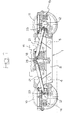
- a bogie for railway vehicles comprises a frame 1 formed by two longitudinal members 2, 3 connected by two transverse members 4, 5 and carrying, near to the respective ends, two axles 6, 7.
- Each axle 6, 7 is comprised in a conventional way of a shaft 8, 9 supporting a pair of wheels 10, 11 and the ends of which are connected to the longitudinal members 2, 3 of the frame 1 through respective journal boxes 12, 13 of a conventional type.
- Primary suspension members also of a conventional type, generally designated as 14, 15 in figure 1, are provided between the frame 1 of the bogie and the axles 6, 7.
- References numeral 16 indicates a load bearing transom arranged above the center area of the frame 1, parallelly to the transverse members 4, 5, which is intended to be rigidly secured to the floor of a railway vehicle body. Between the load bearing transom 16 and the frame 1 secondary vertical and lateral suspension springs 17 are interposed, also in a conventional fashion, through which the necessary rotations of the bogie relative to the body around a vertical axis are also enabled.
- the bogie is also equipped with vertical shock absorbers 18 arranged at one side of the suspension springs 17 between the center areas of the longitudinal members 2, 3 and the load bearing transom 16, and with lateral shock absorbers 19 located transversally with one end thereof articulated to a respective longitudinal member 2, 3 and the opposite end thereof intended to be articulated to a corresponding attachment element fixed to the floor of the railway vehicle body.
- reference numerals 20 diagrammatically designate two linear, normally hydraulic actuators arranged transversally and included in an active lateral suspension system operating, in a way known per se, when the railway vehicle is travelling along a curve.
- the bogie may further be equipped with a tilt system of the body around its longitudinal axis, also known per se, acting to balance the non-compensated centrifugal force along a curve.
- the bogie is provided with a hunting absorbing system which, according to the invention, comprises two pairs of juxtaposed telescopic dampers 21, 22 arranged at the opposite sides of the frame 1.
- each hunting damper 21, 22 has one end pivotally connected to a bracket 23, 24 fixedly secured to the journal box 12, 13 of a corresponding axle 6, 7, and the other end pivotally connected to the load bearing transom 16.
- each end of the transom 16 is lowerly provided with a central attachment element 25, 26 for the pivoted connection of the corresponding hunting dampers 21 and 22, respectively.
- a further and remarkable advantage which may be achieved through the invention consists of that the dampers 21, 22 can provide, in addition to the anti- hunting function, the task of vertical shock absorbers and/or lateral shock absorbers.
Abstract
Description
- The present invention is related to railway vehicle bogies, of the type comprising a frame, two axles whose shafts are connected to the frame through respective journal boxes, a load bearing transom located above the center area of the frame and intended to be fixed to a railway vehicle body, resilient suspension means interposed between the center area of the frame and the load bearing transom, vertical shock absorber means and lateral shock absorber means operatively associated to said resilient suspension means, and hunting absorber means arranged substantially longitudinally at the opposite sides of the bogie.
- Traditionally, in the railway vehicle bogies of the above-referenced type the hunting absorber means comprise, at each bogie side, a single damper interposed substantially horizontally, between the bogie frame and the corresponding end of the load bearing transom to be secured to the railway vehicle body.
- This arrangement, besides involving huge amounts of energy to be dissipated, exhibits functional limits deriving from the fact that intervention of the hunting absorbers to avoid axle instability is indirect, since as previously explained these absorbers operate between the body and the bogie frame.
- The object of the present invention is to overcome the above drawbacks, and to provide a railway vehicle bogie of the type defined at the beginning, having enhanced functional efficiency in connection to the damping of hunting instability, and thus providing improved dynamic behaviour.
- A further object of the invention is to simplify the bogie construction, with particular reference to the arrangement of the vertical shock absorber means and/or of the lateral shock absorber means.
- In order to achieve the above objects, the invention is directed to a railway vehicle bogie of the type set forth at the beginning, the main feature of which resides in that said hunting absorber means comprise, at each bogie side, a pair of symetrically disposed telescopic dampers each having one end pivotally connected to the load bearing transom and the opposite end pivotally connected to the corresponding journal box of a respective axle.
- By virtue of this idea of solution, the anti-hunting performance of the bogie according to the invention is remarkably enhanced, since the two pairs of hunting absorbers directly operate on the axles, thus avoiding that instability thereof be transmitted to the bogie frame and from the latter to the railway vehicle body. Improvement of the bogie stability is equivalent to a reduction of the hunting oscillation transmitted thereby to the body, thus resulting into a better travel comfort for the passengers of a railway vehicle equipped with bogies according to the invention. Moreover, the energy which has to be dissipated by the hunting absorbers is lower than in the case of the traditional bogies.
- A further advantage of the arrangement according to the invention, which is particularly appreciable in the case of a railway vehicle not provided with a body tilt system for balancing the non-compensated centrifugal acceleration along a curve, resides in that the two pairs of hunting dampers apply steering forces onto the axles along the entry and exit sections of the curve.
- According to a preferred embodiment of the invention, the telescopic hunting dampers of each pair are arranged obliquely: particularly, inclination thereof in the vertical plane is about 10-20°, conveniently between 12° and 15°, and inclination thereof in the horizontal plane is about 4-6°.
- This arrangement, besides enhancing the said self-steering effect of the axles, additionally enables employing the two pairs of hunting dampers possibly even for integrating or replacing the vertical shock absorber function and/or the lateral shock absorber function. At the best, the vertical shock absorbers and/or the lateral shock absorbers provided in the traditional railway vehicle bogies may be suppressed, thus achieving evident advantages in terms of construction simplicity and weight, encumbrance and cost reduction.
- The invention will now be disclosed in detail with reference to the accompanying drawings, purely provided by way of non limiting example, in which:
- figure 1 is a diagrammatic lateral elevational view of a railway vehicle bogie according to a first embodiment of the invention,
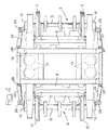
- figure 2 is a plan view from above of figure 1,
- figure 3 is a view same as figure 1 showing a second embodiment of the railway vehicle bogie according to the invention, and
- figure 4 is a plan view from the above of figure 3.
- Referring initially to figures 1 and 2, a bogie for railway vehicles according to the invention comprises a
frame 1 formed by twolongitudinal members transverse members axles 6, 7. Eachaxle 6, 7 is comprised in a conventional way of ashaft wheels longitudinal members frame 1 throughrespective journal boxes - Primary suspension members also of a conventional type, generally designated as 14, 15 in figure 1, are provided between the
frame 1 of the bogie and theaxles 6, 7. -
References numeral 16 indicates a load bearing transom arranged above the center area of theframe 1, parallelly to thetransverse members load bearing transom 16 and theframe 1 secondary vertical andlateral suspension springs 17 are interposed, also in a conventional fashion, through which the necessary rotations of the bogie relative to the body around a vertical axis are also enabled. - In the example shown in figure 1, the bogie is also equipped with
vertical shock absorbers 18 arranged at one side of thesuspension springs 17 between the center areas of thelongitudinal members load bearing transom 16, and withlateral shock absorbers 19 located transversally with one end thereof articulated to a respectivelongitudinal member reference numerals 20 diagrammatically designate two linear, normally hydraulic actuators arranged transversally and included in an active lateral suspension system operating, in a way known per se, when the railway vehicle is travelling along a curve. The bogie may further be equipped with a tilt system of the body around its longitudinal axis, also known per se, acting to balance the non-compensated centrifugal force along a curve. - The bogie is provided with a hunting absorbing system which, according to the invention, comprises two pairs of juxtaposed
telescopic dampers frame 1. Namely, eachhunting damper bracket journal box corresponding axle 6, 7, and the other end pivotally connected to theload bearing transom 16. In the example shown in figures 1 and 2, each end of thetransom 16 is lowerly provided with acentral attachment element corresponding hunting dampers - The
dampers - By virtue of the above disclosed arrangement of the
hunting dampers - higher bogie stabilization efficiency, due to direct
intervention of the
dampers axles 6, 7. This enables both to reduce the energy to be dissipated, and to increase the intervention speed and damping efficiency as compared with the conventional construction in which the hunting absorbers are interposed between the vehicle body and the frame of the bogie; - the symmetry in the vertical plane determines cancellation of the vertical forces related to the movements in the horizontal plane, and consequently vertical vibration excitation of the vehicle body is prevented;
- in the case of standard vehicles (i.e. without body tilt
system), steering forces on the
axles 6, 7 are applied when running entry and exit curve sections. - A further and remarkable advantage which may be achieved through the invention consists of that the
dampers - Figures 3 and 4 show a second embodiment of the invention, in which the vertical and lateral shock absorbers 18 and 19 of the previously disclosed embodiment are suppressed, and the function thereof is performed by the two pairs of
dampers dampers dampers load bearing transom 16, closer to theaxles 6, 7, i.e. in correspondence ofattachment members load bearing transom 16. - Naturally intermediate configurations between the arrangement depicted in figures 1 and 2 and the construction shown in figures 3 and 4 can be envisaged, wherein only the vertical shock absorbers 18 or only the
lateral shock absorbers 19 are suppressed. In such a case thedampers - Naturally the details of construction and the embodiments may be widely varied with respect to what has been disclosed and illustrated, without thereby departing from the scope of the present invention, such as defined in the appended claims.
Claims (6)
- A railway vehicle bogie including a frame (1), two axles (6, 7) whose shafts (8, 9) are connected to the frame (1) through respective journal boxes (12, 13), a load bearing transom (16) located above the center area of the frame (1) and intended to be fixed to a railway vehicle body, resilient suspension means (17) interposed between said center area of the frame (1) and said load bearing transom (16), vertical shock absorber means (18) and lateral shock absorber means (19) operatively associated to said resilient suspension means (17), and hunting absorber means (21, 22) arranged substantially longitudinally at the opposite sides of the bogie, characterized in that said hunting absorber means comprise at each bogie side, a pair of symetrically disposed telescopic dampers (21, 22) each having one end pivotally connected to said load bearing transom (16) and the opposite end pivotally connected to the corresponding journal box (12, 13) of a respective axle (8, 9).
- Bogie according to claim 1, characterized in that the telescopic hunting dampers (21, 22) of each pair are arranged obliquely.
- Bogie according to claim 2, characterized in that the telescopic hunting dampers (21, 22) of each pair are inclined in the vertical plane of about 10-20°, preferably between 12° and 15°.
- Bogie according to claim 2, characterized in that the hunting telescopic dampers (21, 22) of each pair are inclined in the horizontal plane of about 4-6°.
- Bogie according to any of claims 1 through 4, characterized in that said telescopic hunting dampers (21, 22) also constitute said vertical shock absorber mean.
- Bogie according to any of claims 1 through 4, characterized in that said telescopic hunting dampers (21, 22) also constitute said lateral shock absorber means.
Applications Claiming Priority (2)
| Application Number | Priority Date | Filing Date | Title |
|---|---|---|---|
| IT96TO000591A IT1286164B1 (en) | 1996-07-11 | 1996-07-11 | TROLLEY FOR RAILWAY VEHICLES. |
| ITTO960591 | 1996-07-11 |
Publications (3)
| Publication Number | Publication Date |
|---|---|
| EP0818375A2 EP0818375A2 (en) | 1998-01-14 |
| EP0818375A3 EP0818375A3 (en) | 1999-03-31 |
| EP0818375B1 true EP0818375B1 (en) | 2001-05-23 |
Family
ID=11414771
Family Applications (1)
| Application Number | Title | Priority Date | Filing Date |
|---|---|---|---|
| EP96830653A Expired - Lifetime EP0818375B1 (en) | 1996-07-11 | 1996-12-24 | Railway vehicle bogie |
Country Status (8)
| Country | Link |
|---|---|
| EP (1) | EP0818375B1 (en) |
| AT (1) | ATE201361T1 (en) |
| DE (1) | DE69612974T2 (en) |
| DK (1) | DK0818375T3 (en) |
| ES (1) | ES2159350T3 (en) |
| GR (1) | GR3036428T3 (en) |
| IT (1) | IT1286164B1 (en) |
| PT (1) | PT818375E (en) |
Families Citing this family (3)
| Publication number | Priority date | Publication date | Assignee | Title |
|---|---|---|---|---|
| DE202007013300U1 (en) * | 2007-09-21 | 2009-02-12 | Liebherr-Aerospace Lindenberg Gmbh | Active hydraulic damper and hydraulic actuator |
| CN104085418A (en) * | 2014-07-22 | 2014-10-08 | 南车株洲电力机车有限公司 | Locomotive vehicle bogie and anti-snaking shock absorber arrangement structure thereof |
| DE102017128598B4 (en) * | 2017-12-01 | 2019-10-31 | Andreas Fiedler | Arrangement for damping the roll and stabilizing a car body for land vehicles |
Family Cites Families (4)
| Publication number | Priority date | Publication date | Assignee | Title |
|---|---|---|---|---|
| DE1302530B (en) * | 1960-05-24 | |||
| FI82424C (en) * | 1989-05-24 | 1991-03-11 | Valmet Oy | BOGGIEKONSTRUKTION FOER JAERNVAEGSVAGN. |
| US5107773A (en) * | 1990-09-27 | 1992-04-28 | Dofasco Inc. | Railway trucks |
| DE4122741A1 (en) * | 1991-07-10 | 1993-01-14 | Waggon Union Gmbh | BOG FOR FAST-SPEED RAIL VEHICLES |
-
1996
- 1996-07-11 IT IT96TO000591A patent/IT1286164B1/en active IP Right Grant
- 1996-12-24 EP EP96830653A patent/EP0818375B1/en not_active Expired - Lifetime
- 1996-12-24 PT PT96830653T patent/PT818375E/en unknown
- 1996-12-24 ES ES96830653T patent/ES2159350T3/en not_active Expired - Lifetime
- 1996-12-24 AT AT96830653T patent/ATE201361T1/en not_active IP Right Cessation
- 1996-12-24 DK DK96830653T patent/DK0818375T3/en active
- 1996-12-24 DE DE69612974T patent/DE69612974T2/en not_active Expired - Fee Related
-
2001
- 2001-08-20 GR GR20010401279T patent/GR3036428T3/en not_active IP Right Cessation
Also Published As
| Publication number | Publication date |
|---|---|
| ES2159350T3 (en) | 2001-10-01 |
| DE69612974D1 (en) | 2001-06-28 |
| ATE201361T1 (en) | 2001-06-15 |
| GR3036428T3 (en) | 2001-11-30 |
| DE69612974T2 (en) | 2001-10-25 |
| EP0818375A2 (en) | 1998-01-14 |
| PT818375E (en) | 2001-09-28 |
| ITTO960591A0 (en) | 1996-07-11 |
| IT1286164B1 (en) | 1998-07-07 |
| EP0818375A3 (en) | 1999-03-31 |
| ITTO960591A1 (en) | 1998-01-11 |
| DK0818375T3 (en) | 2001-09-10 |
Similar Documents
| Publication | Publication Date | Title |
|---|---|---|
| EP3473514B1 (en) | Bolster of bogie | |
| US4134343A (en) | Radial axle railway truck | |
| US4448131A (en) | Suspension system for rail vehicles | |
| RU2083405C1 (en) | Bogie for high-speed railway train | |
| US6375203B1 (en) | Front air spring suspension with leading arm trailing and V-link | |
| CN111348067B (en) | Bogie and rail vehicle | |
| CN112356871A (en) | Bogie for inner axle box of railway vehicle | |
| EP0547010B1 (en) | A multipurpose rail bogie truck | |
| US3782294A (en) | Articulated railway truck swinging bolster | |
| EP0818375B1 (en) | Railway vehicle bogie | |
| JPH07172314A (en) | Railway vehicle and truck for railway vehicle | |
| JP3498258B2 (en) | 2-axle bogie for railway vehicles | |
| US6276282B1 (en) | Rail vehicle with engine and wagon | |
| JP2002046603A (en) | Anti-rolling device of rolling stock | |
| JP3845144B2 (en) | Bolsterless trolley for vehicles | |
| JPH0292770A (en) | Antirolling device for bolsterless bogie | |
| CN111994113A (en) | Bogie and rail vehicle | |
| KR0140530Y1 (en) | Structure for supporting leaf springs of primary suspension system in a railcar | |
| RU2291801C2 (en) | Railway vehicle two-axle bogie | |
| GB2123773A (en) | Rail vehicle truck | |
| US5438932A (en) | Running gear for a railborne vehicle that is radially adjustable through compensating levers | |
| CN111348066B (en) | Framework, bogie and rail vehicle | |
| JP4066129B2 (en) | Vehicle support structure | |
| RU1794730C (en) | Two-axle frameless bogie of rail vehicle | |
| GB2237544A (en) | Low bogie structure for a railway vehicle |
Legal Events
| Date | Code | Title | Description |
|---|---|---|---|
| PUAI | Public reference made under article 153(3) epc to a published international application that has entered the european phase |
Free format text: ORIGINAL CODE: 0009012 |
|
| AK | Designated contracting states |
Kind code of ref document: A2 Designated state(s): AT BE CH DE DK ES FI FR GB GR IE IT LI NL PT SE |
|
| AX | Request for extension of the european patent |
Free format text: SI PAYMENT 970113 |
|
| PUAL | Search report despatched |
Free format text: ORIGINAL CODE: 0009013 |
|
| AK | Designated contracting states |
Kind code of ref document: A3 Designated state(s): AT BE CH DE DK ES FI FR GB GR IE IT LI NL PT SE |
|
| AX | Request for extension of the european patent |
Free format text: SI PAYMENT 970113 |
|
| 17P | Request for examination filed |
Effective date: 19990710 |
|
| AKX | Designation fees paid |
Free format text: AT BE CH DE DK ES FI FR GB GR IE IT LI NL PT SE |
|
| AXX | Extension fees paid |
Free format text: SI PAYMENT 19970113 |
|
| RBV | Designated contracting states (corrected) |
Designated state(s): AT BE CH DE DK ES FI FR GB GR IE IT LI NL PT SE |
|
| GRAG | Despatch of communication of intention to grant |
Free format text: ORIGINAL CODE: EPIDOS AGRA |
|
| GRAG | Despatch of communication of intention to grant |
Free format text: ORIGINAL CODE: EPIDOS AGRA |
|
| GRAH | Despatch of communication of intention to grant a patent |
Free format text: ORIGINAL CODE: EPIDOS IGRA |
|
| 17Q | First examination report despatched |
Effective date: 20000824 |
|
| GRAH | Despatch of communication of intention to grant a patent |
Free format text: ORIGINAL CODE: EPIDOS IGRA |
|
| GRAA | (expected) grant |
Free format text: ORIGINAL CODE: 0009210 |
|
| RBV | Designated contracting states (corrected) |
Designated state(s): AT BE CH DE DK ES FI FR GB GR IE IT LI NL PT SE |
|
| RBV | Designated contracting states (corrected) |
Designated state(s): AT BE CH DE DK ES FI FR GB GR IE IT LI NL PT SE |
|
| AK | Designated contracting states |
Kind code of ref document: B1 Designated state(s): AT BE CH DE DK ES FI FR GB GR IE IT LI NL PT SE |
|
| AX | Request for extension of the european patent |
Free format text: SI PAYMENT 19970113 |
|
| REF | Corresponds to: |
Ref document number: 201361 Country of ref document: AT Date of ref document: 20010615 Kind code of ref document: T |
|
| REG | Reference to a national code |
Ref country code: CH Ref legal event code: EP |
|
| REF | Corresponds to: |
Ref document number: 69612974 Country of ref document: DE Date of ref document: 20010628 |
|
| REG | Reference to a national code |
Ref country code: IE Ref legal event code: FG4D |
|
| ITF | It: translation for a ep patent filed |
Owner name: BUZZI, NOTARO&ANTONIELLI D'OULX |
|
| REG | Reference to a national code |
Ref country code: DK Ref legal event code: T3 |
|
| REG | Reference to a national code |
Ref country code: CH Ref legal event code: PUE Owner name: FIAT FERROVIARIA S.P.A. TRANSFER- ALSTOM FERROVIAR Ref country code: CH Ref legal event code: NV Representative=s name: ISLER & PEDRAZZINI AG |
|
| REG | Reference to a national code |
Ref country code: PT Ref legal event code: SC4A Free format text: AVAILABILITY OF NATIONAL TRANSLATION Effective date: 20010709 |
|
| REG | Reference to a national code |
Ref country code: ES Ref legal event code: FG2A Ref document number: 2159350 Country of ref document: ES Kind code of ref document: T3 |
|
| RAP2 | Party data changed (patent owner data changed or rights of a patent transferred) |
Owner name: ALSTOM FERROVIARIA S.P.A. |
|
| ET | Fr: translation filed | ||
| REG | Reference to a national code |
Ref country code: PT Ref legal event code: PC4A Free format text: ALSTOM FERROVIARIA S.P.A. IT Effective date: 20010906 |
|
| NLT2 | Nl: modifications (of names), taken from the european patent patent bulletin |
Owner name: ALSTOM FERROVIARIA S.P.A. |
|
| PGFP | Annual fee paid to national office [announced via postgrant information from national office to epo] |
Ref country code: NL Payment date: 20011221 Year of fee payment: 6 Ref country code: ES Payment date: 20011221 Year of fee payment: 6 |
|
| PG25 | Lapsed in a contracting state [announced via postgrant information from national office to epo] |
Ref country code: IE Free format text: LAPSE BECAUSE OF FAILURE TO SUBMIT A TRANSLATION OF THE DESCRIPTION OR TO PAY THE FEE WITHIN THE PRESCRIBED TIME-LIMIT Effective date: 20011224 Ref country code: GB Free format text: LAPSE BECAUSE OF NON-PAYMENT OF DUE FEES Effective date: 20011224 Ref country code: FI Free format text: LAPSE BECAUSE OF NON-PAYMENT OF DUE FEES Effective date: 20011224 Ref country code: DK Free format text: LAPSE BECAUSE OF NON-PAYMENT OF DUE FEES Effective date: 20011224 Ref country code: AT Free format text: LAPSE BECAUSE OF NON-PAYMENT OF DUE FEES Effective date: 20011224 |
|
| PG25 | Lapsed in a contracting state [announced via postgrant information from national office to epo] |
Ref country code: SE Free format text: LAPSE BECAUSE OF NON-PAYMENT OF DUE FEES Effective date: 20011225 |
|
| PG25 | Lapsed in a contracting state [announced via postgrant information from national office to epo] |
Ref country code: LI Free format text: LAPSE BECAUSE OF NON-PAYMENT OF DUE FEES Effective date: 20011231 Ref country code: CH Free format text: LAPSE BECAUSE OF NON-PAYMENT OF DUE FEES Effective date: 20011231 Ref country code: BE Free format text: LAPSE BECAUSE OF NON-PAYMENT OF DUE FEES Effective date: 20011231 |
|
| REG | Reference to a national code |
Ref country code: GB Ref legal event code: IF02 |
|
| PLBE | No opposition filed within time limit |
Free format text: ORIGINAL CODE: 0009261 |
|
| STAA | Information on the status of an ep patent application or granted ep patent |
Free format text: STATUS: NO OPPOSITION FILED WITHIN TIME LIMIT |
|
| 26N | No opposition filed | ||
| BERE | Be: lapsed |
Owner name: ALSTOM FERROVIARA S.P.A. Effective date: 20011231 |
|
| PG25 | Lapsed in a contracting state [announced via postgrant information from national office to epo] |
Ref country code: DE Free format text: LAPSE BECAUSE OF NON-PAYMENT OF DUE FEES Effective date: 20020702 |
|
| PG25 | Lapsed in a contracting state [announced via postgrant information from national office to epo] |
Ref country code: GR Free format text: LAPSE BECAUSE OF NON-PAYMENT OF DUE FEES Effective date: 20020708 |
|
| EUG | Se: european patent has lapsed |
Ref document number: 96830653.0 |
|
| GBPC | Gb: european patent ceased through non-payment of renewal fee |
Effective date: 20011224 |
|
| REG | Reference to a national code |
Ref country code: CH Ref legal event code: PL |
|
| PG25 | Lapsed in a contracting state [announced via postgrant information from national office to epo] |
Ref country code: FR Free format text: LAPSE BECAUSE OF NON-PAYMENT OF DUE FEES Effective date: 20020830 |
|
| REG | Reference to a national code |
Ref country code: DK Ref legal event code: EBP |
|
| REG | Reference to a national code |
Ref country code: FR Ref legal event code: ST |
|
| REG | Reference to a national code |
Ref country code: IE Ref legal event code: MM4A |
|
| PG25 | Lapsed in a contracting state [announced via postgrant information from national office to epo] |
Ref country code: ES Free format text: LAPSE BECAUSE OF NON-PAYMENT OF DUE FEES Effective date: 20021226 |
|
| PG25 | Lapsed in a contracting state [announced via postgrant information from national office to epo] |
Ref country code: PT Free format text: LAPSE BECAUSE OF NON-PAYMENT OF DUE FEES Effective date: 20030630 |
|
| PG25 | Lapsed in a contracting state [announced via postgrant information from national office to epo] |
Ref country code: NL Free format text: LAPSE BECAUSE OF NON-PAYMENT OF DUE FEES Effective date: 20030701 |
|
| NLV4 | Nl: lapsed or anulled due to non-payment of the annual fee |
Effective date: 20030701 |
|
| REG | Reference to a national code |
Ref country code: PT Ref legal event code: MM4A Free format text: LAPSE DUE TO NON-PAYMENT OF FEES Effective date: 20030630 |
|
| REG | Reference to a national code |
Ref country code: ES Ref legal event code: FD2A Effective date: 20021226 |
|
| PG25 | Lapsed in a contracting state [announced via postgrant information from national office to epo] |
Ref country code: PT Free format text: LAPSE BECAUSE OF NON-PAYMENT OF DUE FEES Effective date: 20011224 |
|
| PGFP | Annual fee paid to national office [announced via postgrant information from national office to epo] |
Ref country code: IT Payment date: 20151228 Year of fee payment: 20 |