EP0818342B1 - Control system for a selectable four-wheel drive transmission - Google Patents
Control system for a selectable four-wheel drive transmission Download PDFInfo
- Publication number
- EP0818342B1 EP0818342B1 EP97202107A EP97202107A EP0818342B1 EP 0818342 B1 EP0818342 B1 EP 0818342B1 EP 97202107 A EP97202107 A EP 97202107A EP 97202107 A EP97202107 A EP 97202107A EP 0818342 B1 EP0818342 B1 EP 0818342B1
- Authority
- EP
- European Patent Office
- Prior art keywords
- driven
- drive
- transmission according
- passages
- collar
- Prior art date
- Legal status (The legal status is an assumption and is not a legal conclusion. Google has not performed a legal analysis and makes no representation as to the accuracy of the status listed.)
- Expired - Lifetime
Links
- 230000005540 biological transmission Effects 0.000 title claims description 34
- 230000008878 coupling Effects 0.000 claims description 24
- 238000010168 coupling process Methods 0.000 claims description 24
- 238000005859 coupling reaction Methods 0.000 claims description 24
- 239000012530 fluid Substances 0.000 claims description 16
- 230000033001 locomotion Effects 0.000 claims description 14
- 238000004891 communication Methods 0.000 claims description 3
- 230000001419 dependent effect Effects 0.000 claims description 3
- 230000009471 action Effects 0.000 claims description 2
- 230000008859 change Effects 0.000 description 2
- 238000006073 displacement reaction Methods 0.000 description 2
- 230000004044 response Effects 0.000 description 2
- 238000010276 construction Methods 0.000 description 1
- 230000001276 controlling effect Effects 0.000 description 1
- 239000000463 material Substances 0.000 description 1
- 230000007246 mechanism Effects 0.000 description 1
- 230000001105 regulatory effect Effects 0.000 description 1
Images

Classifications
-
- B—PERFORMING OPERATIONS; TRANSPORTING
- B60—VEHICLES IN GENERAL
- B60K—ARRANGEMENT OR MOUNTING OF PROPULSION UNITS OR OF TRANSMISSIONS IN VEHICLES; ARRANGEMENT OR MOUNTING OF PLURAL DIVERSE PRIME-MOVERS IN VEHICLES; AUXILIARY DRIVES FOR VEHICLES; INSTRUMENTATION OR DASHBOARDS FOR VEHICLES; ARRANGEMENTS IN CONNECTION WITH COOLING, AIR INTAKE, GAS EXHAUST OR FUEL SUPPLY OF PROPULSION UNITS IN VEHICLES
- B60K23/00—Arrangement or mounting of control devices for vehicle transmissions, or parts thereof, not otherwise provided for
- B60K23/08—Arrangement or mounting of control devices for vehicle transmissions, or parts thereof, not otherwise provided for for changing number of driven wheels, for switching from driving one axle to driving two or more axles
-
- B—PERFORMING OPERATIONS; TRANSPORTING
- B60—VEHICLES IN GENERAL
- B60K—ARRANGEMENT OR MOUNTING OF PROPULSION UNITS OR OF TRANSMISSIONS IN VEHICLES; ARRANGEMENT OR MOUNTING OF PLURAL DIVERSE PRIME-MOVERS IN VEHICLES; AUXILIARY DRIVES FOR VEHICLES; INSTRUMENTATION OR DASHBOARDS FOR VEHICLES; ARRANGEMENTS IN CONNECTION WITH COOLING, AIR INTAKE, GAS EXHAUST OR FUEL SUPPLY OF PROPULSION UNITS IN VEHICLES
- B60K17/00—Arrangement or mounting of transmissions in vehicles
- B60K17/34—Arrangement or mounting of transmissions in vehicles for driving both front and rear wheels, e.g. four wheel drive vehicles
Definitions
- the present invention relates to a control system for automatically changing between two-wheel and four-wheel drive in an off-road vehicle, such as an agricultural tractor.
- two-wheel drive is preferred to four-wheel drive because even when the front axle differential is not locked, the front wheel on the outside of the bend tends to travel up to 20% faster than the rear wheels so that, if four-wheel drive would be engaged, this front wheel would slip, again causing considerable wear on the tyre.
- a tractor it is desirable in a tractor to be able to select between two-wheel and four-wheel drive in dependence upon the road surface on which the tractor is driven.
- the tractor should have four-wheel drive engaged only under poor road adhesion conditions when the rear wheels slip with respect to the ground.
- EP-A-0.432.549 discloses a control system for automatically engaging four-wheel drive in a vehicle transmission.
- the transmission comprises a first drive shaft for transmitting drive from the engine to two rear wheels and a second drive shaft for transmitting drive to two front wheels.
- a clutch acts, when engaged, to couple the two drive shafts for rotation with one another and the drive transmission geometry is such that, with the clutch engaged, the transmission causes the said front wheels to be driven slightly slower than the rear wheels.
- a special coupling which comprises toothed drive and driven members that mesh with one another with lost motion, that is to say, the two members can rotate one relative to the other through a limited angle.
- Relative rotation of the drive and driven members of the coupling is sensed by an element adapted to move axially between two end positions as the lost motion in the coupling is taken up to indicate the direction in which torque is being transmitted through the coupling.
- a sensor detects the end positions of the latter element and generates an electrical signal that is used by an electronic processing unit to control engagement or disengagement of the clutch.
- the electronic processing unit controls the four-wheel drive clutch to either engage or to disengage.
- a further automatic clutch arrangement for selectively engaging a four-wheel drive of a vehicle.
- the arrangement comprises a rotary fluid valve with an internal lost motion mechanism to detect the presence or absence of slip in the drive arrangement.
- a multi-plate friction clutch is controlled to engage when four-wheel drive is required.
- a clutch of this type inherently comprises a piston/cylinder arrangement for engaging the clutch plates, a complicated structure is needed to associate the function of the rotary valve with the multi-plate clutch.
- the first member is a drive member rotatable with the rear wheels of the vehicle and the second member comprises a driven member rotatable with the front wheels.
- the rotary fluid valve comprises a collar interposed between the driven member and a driven shaft connected to the front axle of the vehicle.
- the driven member is fast in rotation with and axially slidable relative to the collar whereas the collar is axially fast with the driven shaft but rotatable relative thereto through a limited angle.
- a friction ring is provided for applying frictional drive between the drive member and the collar.
- Supply and return fluid passages pass through the driven shaft and ports are provided in the collar which align with the passages in the driven shaft only in predetermined angular positions of the collar relative to the driven shaft to establish fluid communication between the jacking means and the supply or return fluid passage in the driven shaft.
- the jacking means are constituted by a pressure chamber defined between the driven member and the collar.
- a drive shaft 10 (shown only in Figure 1) is driven by the engine (not shown) of a tractor through a variable ratio gearbox and is connected (also not shown) to drive the rear axle of a tractor.
- the drive shaft 10 is journalled in a bearing 18 for rotation within the transmission housing.
- the gearbox driving the shaft 10 is not shown in detail in the drawing as it is not material to the present invention.
- a coupling that is generally designated 100.
- the coupling 100 When the coupling 100 is engaged, all four-wheels of the tractor are driven whereas when it is disengaged, only the rear wheels are driven.
- a gear 12 (shown only in Figure 1) mounted fast in rotation with the drive shaft 10 meshes with a gear 14 acting as the drive member of the coupling 100.
- the gear 14 is freely rotatable about the driven shaft 16 and has axially projecting dog teeth 22.
- a driven member 26 can slide axially relative to the driven shaft 16 and has teeth 24 that project axially towards the teeth 22 of the gear 14. When the driven member 26 is in the right hand end position illustrated in Figures 1 and 2, the teeth 22 and 24 are disengaged from one another. On the other hand, when the driven member is in its left hand end position, then the teeth 22 and 24 engage to transmit torque from the gear 14 to the driven member 26.
- a collar 34 is interposed between the driven member 26 and the driven shaft 16.
- the collar 34 is connected by splines 36 to the driven member 26 so that the driven member 26 may slide axially over the collar 34 but may not rotate relative to it.
- the collar 34 has inwardly directed teeth 38 that mesh with clearance with teeth 40 on the driven shaft 16.
- the collar 34 is frictionally driven by the gear 14 through a friction ring constructed as a spring 42 that acts as a slipping clutch urging the collar to the right as viewed in the drawings against a circlip 44.
- An annular working chamber 50 is defined between two shoulders on the collar 34 and the driven member 26, respectively.
- the working chamber 50 is sealed by means of two O-rings that are located in annular recesses in the collar 34.
- a spring 28 surrounding the driven member 26 acts between a shoulder on the driven member 26 and an abutment plate 30 that is prevented from moving relative to the collar 34 by means of a circlip 32. The spring 28 biases the driven member 26 towards the left hand end position in which the teeth 22 and 24 mesh with one another and the volume of the working chamber 50 is at its minimum.
- Two passages 46, 48 are formed in the driven shaft and are individually connectible to the working chamber 50 through ports 52 formed in the collar 34.
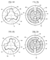
- Figures 6A, 6B and 7A, 7B For ease of understanding, in Figures 6A and 6B only three teeth 38 and 40 are shown. It will be appreciated however that a larger number of teeth may be provided, such as shown in Figure 2, the only requirement being that there is enough free play inbetween the corresponding teeth 38 and 40 to enable a lost motion to occur. Supposing as an example that in Figure 6A the arrangement is rotating in a clockwise direction, corresponding to the forward drive of the tractor, then the driven shaft 16 is attempting to rotate faster than the collar 34 whereby the clockwise surfaces of the teeth 40 engage the anti-clockwise surfaces of the teeth 38. This is the condition when no slip of the wheels is experienced. In this position, as best seen in Figure 7A, the first passage 46 is connected to the working chamber 50 through one of the ports 52 while the second passage 48 is disconnected from said chamber 50 in as much as the other port 52 is angularly offset from the passage 48.
- the circuit supplying hydraulic fluid to the working chamber 50 by way of the passages 46 and 48 and the rotary valve constituted by the collar 34 is shown schematically under different conditions in Figures 3A to 5B.
- the circuit comprises a pump 110 that draws fluid from a reservoir 112 and supplies it by way of a pressure regulating valve 114 (e.g. set at a maximum pressure of 16 bar), to a three position, four port solenoid operated valve 116.
- a second inlet of the valve 116 is connected to the reservoir or drain 112.
- the outlet ports of the valve 116 are connected to the two passages 46 and 48, respectively, that lead to the working chamber 50 by way of the ports 52 controlled by the rotary valve constituted by the collar 34.
- the solenoids of the valve 116 are supplied with current by an electrical circuit that comprises a battery 104 and a switch 106 that is manually operated to select permanently engaged four-wheel drive (when the switch is open) or automatic mode selection (when the switch is closed).
- a further switch 109 that is closed when the forward-reverse lever 102 is in its reverse position operates a four pole two position relay the switching contacts of which are arranged in series with the switch 106 in the line supplying power to the solenoids of the valve 116.
- the solenoid valve takes up the central position shown in Figures 3A and 3B in which both the passages 46 and 48 are connected to the drain 112.
- the switch 106 is closed, the position of the solenoid valve will depend on the position of the lever 102.
- the solenoid valve takes up the position shown in Figures 4A and 5A in which the passage 48 is connected to the pressure regulator 114 and the passage 46 is connected to drain. Conversely, if the lever 102 is in the reverse drive position, then the solenoid valve takes up the position shown in Figures 4B and 5B in which the passage 46 is connected to the pressure regulator 114 and the passage 48 is connected to drain.
- both the passages 46 and 48 are connected to drain as shown in Figures 3A and 3B, representing respectively forward and rearward drive.
- Neither of the passages 46 and 48 is under pressure and regardless of which of these passages is connected to the working chamber 50 by the rotary valve 34, the working chamber 50 will not be under pressure. Consequently, whatever the position of the rotary valve 34, and therefore regardless of whether effectively slip is experienced or not, the chamber 50 is not pressurized.
- the spring 28 will act to move the driven member 26 into its left hand end position (with reference to Figures 1 and 2) for engagement between the teeth 22 and 24.
- Torque will therefore be transmitted from the gear 14 to the driven member 26 through the teeth 22, 24, from the driven member 26 to the collar 34 by the splines 36 and from the collar 34 to the driven shaft 16 through the teeth 38, 40.
- Such permanent four-wheel drive will normally be engaged in off-road conditions in which the rear wheels mostly will tend to slip and therefore will be turning faster than the front wheels so that the lost motion between the teeth 22 and 24 will permanently be taken up in the direction of transmitting torque from the rear wheels to the front wheels.
- the working chamber 50 is now connected to the pressure supply through the passage 48 and the expansion of the working chamber 50 will move the driven member 26 against the action of the spring 28, at the same time disengaging the drive between the gear 14 and the driven member 26, as shown in Figure 4A.
- Such disengagement will also occur automatically when the tractor is steered in the one or other direction because the front wheels will move over a larger turning radius than the rear wheels. As such, they will be required to cover a longer distance and therefore will rotate faster.
- Figure 6B on the other hand now corresponds to the non-slip condition whereby the driven shaft 16 is attempting to rotate faster than the collar 34. It thus is seen that when changing from forward to rearward drive, the function of Figures 6A and 6B is reversed. This also means that the function of Figures 7A and 7B is reversed whereby it hence is necessary to shift the valve 116 from one extreme position to the other when the drive direction is reversed so as to reverse the function of the passages 46 and 48.
- the coupling 100 thus acts as a means of automatic mode selection in dependence upon wheel slip which can be overridden by varying the pressures applied to the passages 46 and 48, to engage or disengage four-wheel drive. For example, if the tractor is sensed to be on a severe incline, then it is desirable to engage four-wheel drive regardless of the relative speed of the front and rear wheels and this can be achieved by connecting both the passages 46 and 48 to drain by opening the switch 106.
- valve 116 it further is possible to install an additional two-position valve inbetween the pressure regulator 114 and the drain 112 on the one hand and the valve 116 on the other hand enabling permanent two-wheel drive if so desired.
- both inlet ports of valve 116 would be pressurized through the regulator 114 whereby the chamber 50 permanently would be under pressure and hence the teeth 22 and 24 never would become engaged.
Landscapes
- Engineering & Computer Science (AREA)
- Chemical & Material Sciences (AREA)
- Combustion & Propulsion (AREA)
- Transportation (AREA)
- Mechanical Engineering (AREA)
- Arrangement And Driving Of Transmission Devices (AREA)
- Arrangement And Mounting Of Devices That Control Transmission Of Motive Force (AREA)
Description
- The present invention relates to a control system for automatically changing between two-wheel and four-wheel drive in an off-road vehicle, such as an agricultural tractor.
- In an agricultural tractor provided with a conventional clutch to engage four-wheel drive, when the clutch is engaged, the front wheels are normally driven by about 2% faster than the rear wheels. This speed differential is caused by the geometry of the transmission members fitted to the front wheels. In the field, that is when the tractor is travelling over agricultural ground, because of the low speed at which the tractor normally runs and because of the fact that the agricultural ground offers a low adhesion to the tyres, it is established that with the four-wheel drive transmission engaged all the wheels may slip even by up to 10-15% with respect to the speed imposed by the engine of the tractor so that the difference in speed between the front wheels and the rear wheels is not noticed.
- On metalled road surfaces, however, because the tractor tends to be driven at higher speeds and because there is better adhesion between the tyres and the road surface, there is a considerable slipping of the front wheels on the ground when four-wheel drive is engaged. The front wheels slip in preference to the rear wheels because in tractors most of the weight is supported by the rear wheels and the frictional force on the ground at the rear wheels is greater than at the front wheels.
- Because the slipping of the front wheels on metalled road surfaces causes a high degree of wear on the front tyres, it is preferred to disengage the clutch and revert to two-wheel drive when driving on good road surfaces.
- Furthermore, on bends, especially on those of a short radius, two-wheel drive is preferred to four-wheel drive because even when the front axle differential is not locked, the front wheel on the outside of the bend tends to travel up to 20% faster than the rear wheels so that, if four-wheel drive would be engaged, this front wheel would slip, again causing considerable wear on the tyre.
- For these reasons, it is desirable in a tractor to be able to select between two-wheel and four-wheel drive in dependence upon the road surface on which the tractor is driven. Ideally, the tractor should have four-wheel drive engaged only under poor road adhesion conditions when the rear wheels slip with respect to the ground.
- In the prior art, it is known to provide a transmission in which two-wheel and four-wheel drive can be selected by the operator of the tractor, but this requires the operator to have the skill to know when to change between four-wheel and two-wheel drive for the best traction and minimum tyre wear.
- To simplify the task of the operator, it has already been proposed to provide a transmission with a control system that can automatically select four-wheel drive, whenever required to reduce slipping of the rear wheels.
- EP-A-0.432.549 discloses a control system for automatically engaging four-wheel drive in a vehicle transmission. The transmission comprises a first drive shaft for transmitting drive from the engine to two rear wheels and a second drive shaft for transmitting drive to two front wheels. A clutch acts, when engaged, to couple the two drive shafts for rotation with one another and the drive transmission geometry is such that, with the clutch engaged, the transmission causes the said front wheels to be driven slightly slower than the rear wheels.
- In the second drive shaft, a special coupling is provided which comprises toothed drive and driven members that mesh with one another with lost motion, that is to say, the two members can rotate one relative to the other through a limited angle. Relative rotation of the drive and driven members of the coupling is sensed by an element adapted to move axially between two end positions as the lost motion in the coupling is taken up to indicate the direction in which torque is being transmitted through the coupling. A sensor detects the end positions of the latter element and generates an electrical signal that is used by an electronic processing unit to control engagement or disengagement of the clutch.
- The principle on which the above proposal is based is that, when the rear wheels slip in two-wheel drive, the drive member of the lost motion coupling will try to rotate faster than the driven member, the speed of the latter corresponding to the road speed of the vehicle. When on the other hand four-wheel drive is engaged and the wheels are not slipping on the ground, then the front wheels will try to roll on the ground faster than the speed at which they are being driven by the transmission with the result that the driven member will try to rotate faster than the drive member and will apply a reverse torque to the engine through the lost motion coupling. During the reversal of the direction of the torque through the coupling, the backlash or lost motion in the coupling is taken up resulting in an angular relative displacement between the drive and the driven members which is translated into an axial displacement of the sensor element. As already mentioned, in response to the movement of the sensor element in the one or other direction, the electronic processing unit controls the four-wheel drive clutch to either engage or to disengage.
- Although the above arrangement has proven to be extremely efficient in practice, it nevertheless suffers from the disadvantage that, apart from the four-wheel drive clutch, a separate lost motion coupling with additional sensor controlling an electronic processing unit is needed to automatically switch between two-wheel drive and four-wheel drive. It will be appreciated that this is not cost-effective and complicates the assembly of the parts and the calibration of the arrangement.
- In US-A-4.286.686, which is believed to represent the closest prior art to the present invention, a further automatic clutch arrangement is shown for selectively engaging a four-wheel drive of a vehicle. The arrangement comprises a rotary fluid valve with an internal lost motion mechanism to detect the presence or absence of slip in the drive arrangement. In response to the relative position of the rotary valve, a multi-plate friction clutch is controlled to engage when four-wheel drive is required. However, in as much as a clutch of this type inherently comprises a piston/cylinder arrangement for engaging the clutch plates, a complicated structure is needed to associate the function of the rotary valve with the multi-plate clutch.
- It is therefore an object of the present invention to provide a coupling which operates on the same principle as described above but which incorporates the function of the rotary valve into a dog-teeth-type clutch so as to obtain a compact and simple design.
- The present invention is defined by the features of claim 1. Preferred details are outlined in the dependent claims.
- The first member is a drive member rotatable with the rear wheels of the vehicle and the second member comprises a driven member rotatable with the front wheels.
- The rotary fluid valve comprises a collar interposed between the driven member and a driven shaft connected to the front axle of the vehicle. The driven member is fast in rotation with and axially slidable relative to the collar whereas the collar is axially fast with the driven shaft but rotatable relative thereto through a limited angle. A friction ring is provided for applying frictional drive between the drive member and the collar. Supply and return fluid passages pass through the driven shaft and ports are provided in the collar which align with the passages in the driven shaft only in predetermined angular positions of the collar relative to the driven shaft to establish fluid communication between the jacking means and the supply or return fluid passage in the driven shaft. The jacking means are constituted by a pressure chamber defined between the driven member and the collar.
- The transmission according to the present invention will now be described in greater detail, by way of example, with reference to the accompanying drawings, in which :
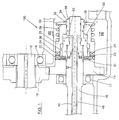
- Figure 1 is a section through a coupling that forms part of a transmission constructed in accordance with the invention;
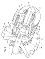
- Figure 2 shows a partly cut-away perspective view of the coupling shown in Figure 1;
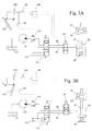
- Figure 3A shows the hydraulic circuit of the coupling in Figures 1 and 2 in which the components of the circuit are shown in the condition when four-wheel drive is permanently engaged and the vehicle is moving forwards;
- Figure 3B shows the same hydraulic circuit with the components in the condition when four-wheel drive is permanently engaged and the vehicle is moving in reverse;
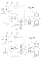
- Figure 4A shows the hydraulic circuit in automatic selection mode when being driven forwards and the front wheels turn faster than the rear wheels;
- Figure 4B shows the hydraulic circuit in automatic selection mode when being driven in reverse and the front wheels turn faster than the rear wheels;
- Figure 5A shows the hydraulic circuit in automatic selection mode when being driven forwards and the rear wheels are slipping on the ground;
- Figure 5B shows the hydraulic circuit in automatic selection mode when being driven in reverse and the rear wheels are slipping on the ground;
- Figure 6A is a sectional view taken along line VI-VI in Figure 1;
- Figure 6B is a view similar to Figure 6A but showing the components in a different relative position;
- Figure 7A is a sectional view taken along line VII-VII in Figure 1; and
- Figure 7B is a view similar to Figure 7A but showing the components in a different relative position.
-
- A drive shaft 10 (shown only in Figure 1) is driven by the engine (not shown) of a tractor through a variable ratio gearbox and is connected (also not shown) to drive the rear axle of a tractor. The
drive shaft 10 is journalled in abearing 18 for rotation within the transmission housing. The gearbox driving theshaft 10 is not shown in detail in the drawing as it is not material to the present invention. - A driven
shaft 16, journalled in abearing 17, transmits torque to the front axle of the tractor and may be selectively coupled to and disconnected from theshaft 10 by a coupling that is generally designated 100. When thecoupling 100 is engaged, all four-wheels of the tractor are driven whereas when it is disengaged, only the rear wheels are driven. - The detailed construction of the
coupling 100 will be better understood from the partly cut-away perspective view of the coupling shown in Figure 2. A gear 12 (shown only in Figure 1) mounted fast in rotation with thedrive shaft 10 meshes with agear 14 acting as the drive member of thecoupling 100. Thegear 14 is freely rotatable about the drivenshaft 16 and has axially projectingdog teeth 22. A drivenmember 26 can slide axially relative to the drivenshaft 16 and hasteeth 24 that project axially towards theteeth 22 of thegear 14. When the drivenmember 26 is in the right hand end position illustrated in Figures 1 and 2, theteeth teeth gear 14 to the drivenmember 26. When the dog teeth are in mesh with one another, there might be a significant intentional free play between the two sets of teeth allowing the driven member 26 a limited degree of rotation relative to thegear 14, avoiding any adherence of theteeth teeth - A
collar 34 is interposed between the drivenmember 26 and the drivenshaft 16. Thecollar 34 is connected bysplines 36 to the drivenmember 26 so that the drivenmember 26 may slide axially over thecollar 34 but may not rotate relative to it. Thecollar 34 has inwardly directedteeth 38 that mesh with clearance withteeth 40 on the drivenshaft 16. Thecollar 34 is frictionally driven by thegear 14 through a friction ring constructed as aspring 42 that acts as a slipping clutch urging the collar to the right as viewed in the drawings against acirclip 44. - An annular working
chamber 50 is defined between two shoulders on thecollar 34 and the drivenmember 26, respectively. The workingchamber 50 is sealed by means of two O-rings that are located in annular recesses in thecollar 34. Aspring 28 surrounding the drivenmember 26 acts between a shoulder on the drivenmember 26 and anabutment plate 30 that is prevented from moving relative to thecollar 34 by means of acirclip 32. Thespring 28 biases the drivenmember 26 towards the left hand end position in which theteeth chamber 50 is at its minimum. - Two
passages chamber 50 throughports 52 formed in thecollar 34. When the free play between theteeth chamber 50 is connected to thefirst passage 46. On the other hand, when the free play is taken up in the other direction of rotation then the workingchamber 50 is connected to thesecond passage 48. - This is more clearly visualised in Figures 6A, 6B and 7A, 7B. For ease of understanding, in Figures 6A and 6B only three
teeth teeth shaft 16 is attempting to rotate faster than thecollar 34 whereby the clockwise surfaces of theteeth 40 engage the anti-clockwise surfaces of theteeth 38. This is the condition when no slip of the wheels is experienced. In this position, as best seen in Figure 7A, thefirst passage 46 is connected to the workingchamber 50 through one of theports 52 while thesecond passage 48 is disconnected from saidchamber 50 in as much as theother port 52 is angularly offset from thepassage 48. - In contrast therewith, again considering in Figure 6B that the arrangement is rotating in the clockwise direction, the
collar 34 is positively driving the drivenshaft 16 whereby the clockwise surfaces of theteeth 38 abut the anti-clockwise surfaces of theteeth 40. Thecollar 34 and drivenshaft 16 take the foregoing relative position when the rear wheels slip relative to the front wheels. With reference to Figure 7B, it is seen that under this condition thesecond passage 48 and thechamber 50 are connected to each other due to one of theports 52 having angularly shifted in line with the outlet of thepassage 48. Thefirst passage 46 on the other hand has lost its connection with thechamber 50 as a result of theother port 52 having shifted out of line with the outlet of thepassage 46. - The circuit supplying hydraulic fluid to the working
chamber 50 by way of thepassages collar 34 is shown schematically under different conditions in Figures 3A to 5B. The circuit comprises apump 110 that draws fluid from areservoir 112 and supplies it by way of a pressure regulating valve 114 (e.g. set at a maximum pressure of 16 bar), to a three position, four port solenoid operatedvalve 116. A second inlet of thevalve 116 is connected to the reservoir or drain 112. The outlet ports of thevalve 116 are connected to the twopassages chamber 50 by way of theports 52 controlled by the rotary valve constituted by thecollar 34. - The solenoids of the
valve 116 are supplied with current by an electrical circuit that comprises abattery 104 and aswitch 106 that is manually operated to select permanently engaged four-wheel drive (when the switch is open) or automatic mode selection (when the switch is closed). Afurther switch 109 that is closed when the forward-reverse lever 102 is in its reverse position operates a four pole two position relay the switching contacts of which are arranged in series with theswitch 106 in the line supplying power to the solenoids of thevalve 116. When theswitch 106 is open, the solenoid valve takes up the central position shown in Figures 3A and 3B in which both thepassages drain 112. When theswitch 106 is closed, the position of the solenoid valve will depend on the position of thelever 102. If thelever 102 is in the forward drive position, then the solenoid valve takes up the position shown in Figures 4A and 5A in which thepassage 48 is connected to thepressure regulator 114 and thepassage 46 is connected to drain. Conversely, if thelever 102 is in the reverse drive position, then the solenoid valve takes up the position shown in Figures 4B and 5B in which thepassage 46 is connected to thepressure regulator 114 and thepassage 48 is connected to drain. - If the tractor is to be driven with permanently engaged four-wheel drive, both the
passages passages chamber 50 by therotary valve 34, the workingchamber 50 will not be under pressure. Consequently, whatever the position of therotary valve 34, and therefore regardless of whether effectively slip is experienced or not, thechamber 50 is not pressurized. As a result, thespring 28 will act to move the drivenmember 26 into its left hand end position (with reference to Figures 1 and 2) for engagement between theteeth gear 14 to the drivenmember 26 through theteeth member 26 to thecollar 34 by thesplines 36 and from thecollar 34 to the drivenshaft 16 through theteeth teeth - If the tractor is to be driven with automatic mode selection, between two-wheel and four-wheel drive, then the
switch 106 is closed. When the tractor is driven forwards, as represented by Figures 4A and 5A, then thepassage 48 is connected to the hydraulic pressure supply while thepassage 46 is connected to drain. Let it first be assumed that theteeth chamber 50 relieved by virtue of being connected through one of theports 52 in thecollar 34 to thepassage 46. Then for as long as the rear wheels rotate faster than the front wheels, indicating that the tractor is being driven under slip conditions, this condition will be maintained and torque will be transmitted to all four wheels in the manner previously described . Throughout this time, therotary valve 34 will be in the position shown in Figure 5A, whereby thechamber 50 is connected to drain through thepassage 46. This position corresponds to the condition as shown in Figures 6B and 7B. - If the tractor now is driven onto a metalled road surface affording a good grip to all four road wheels whereby slip of the rear wheels no longer occurs, then the friction between the front wheels and the ground will attempt to drive them at a higher speed than that at which they are driven by the engine. The front wheels will attempt to drive the engine in overrunning mode and will apply a torque through the
coupling 100 to increase the speed of the engine. As the direction of the torque through the coupling is reversed, the lost motion between theteeth collar 34 relative to the drivenshaft 16 will change (position as shown in Figure 6A), so that the rotary valve moves from the position shown in Figure 5A to that shown in Figure 4A (position corresponding to Figure 7A). The workingchamber 50 is now connected to the pressure supply through thepassage 48 and the expansion of the workingchamber 50 will move the drivenmember 26 against the action of thespring 28, at the same time disengaging the drive between thegear 14 and the drivenmember 26, as shown in Figure 4A. Such disengagement will also occur automatically when the tractor is steered in the one or other direction because the front wheels will move over a larger turning radius than the rear wheels. As such, they will be required to cover a longer distance and therefore will rotate faster. - Should the tractor again be driven in conditions where there is considerable wheel slip, requiring a return to four-wheel drive, then the
collar 34 will again be driven through the slipping clutch constituted by thespring 42 faster than the drivenshaft 16 to take up the free play between theteeth rotary valve 34 to the position represented in Figure 5A. The workingchamber 50 will therefore again be connected to thedrain passage 46, to allow the drivenmember 26 to be moved by thespring 28 to its left hand end position (with reference to Figures 1 and 2) to reengage theteeth - The automatic selection of two and four-wheel drive when the tractor is in reverse takes place in a completely analogous manner to that already described apart from the need to reverse the hydraulic connections to the
passages switch 109 and therelay 108 acting on the solenoids of thevalve 116 to move its valve spool from the position shown in Figures 4A and 5A to the position shown in Figures 4B and 5B. It indeed will be appreciated that in reverse drive, the components shown in Figures 6A and 6B are rotating in the anti-clockwise direction. As such, the position of thecollar 34 and the drivenshaft 16 in Figure 6A now correspond to the rear wheel slip condition whereby thecollar 34 is driven faster than the drivenshaft 16. Figure 6B on the other hand now corresponds to the non-slip condition whereby the drivenshaft 16 is attempting to rotate faster than thecollar 34. It thus is seen that when changing from forward to rearward drive, the function of Figures 6A and 6B is reversed. This also means that the function of Figures 7A and 7B is reversed whereby it hence is necessary to shift thevalve 116 from one extreme position to the other when the drive direction is reversed so as to reverse the function of thepassages - The
coupling 100 thus acts as a means of automatic mode selection in dependence upon wheel slip which can be overridden by varying the pressures applied to thepassages passages switch 106. - Although not shown in the drawings, it further is possible to install an additional two-position valve inbetween the
pressure regulator 114 and thedrain 112 on the one hand and thevalve 116 on the other hand enabling permanent two-wheel drive if so desired. In one position of the additional valve, both inlet ports ofvalve 116 would be pressurized through theregulator 114 whereby thechamber 50 permanently would be under pressure and hence theteeth
Claims (19)
- A transmission for a vehicle having a first permanently engaged axle (-) and a second selectively engaged axle (-), the transmission comprising a coupling (100) for selectively applying torque to the second axle of the vehicle to switch between two-wheel drive and four-wheel drive in dependence upon slipping of the wheels connected to the first axle, which coupling (100) comprises a first member (14) and a second member (26, 34, 50) engageable with one another and arranged to rotate with the first and second axle, respectively; the second member (26, 34, 50) comprising :characterized in that :rotary fluid valve means (34), the position of which is sensitive to slip of the wheels connected to the first axle; andjacking means (50) operative to enable and disable the transmission of drive torque through the coupling (100) by respectively engaging and disengaging the first and second members (14; 26, 34, 50); said valve means (34) controlling the operation of said jacking means (50); andthe first and second members (14 resp. 26, 34, 50) comprise teeth (22, 24) which selectively mesh with one another;the second member (26, 34, 50) further comprises a driven member (26), andthe rotary fluid valve means (34) comprises a collar (34) interposed between the driven member (26) and a driven shaft (16) connected to the selectively engaged axle of the vehicle, said driven member (26) being fast in rotation with and axially slidable relative to the collar (34) by means of splines (36).
- A transmission according to claims 1, characterized in that the first and second axle are operatively connected to the rear and front wheels, respectively, of the vehicle.
- A transmission according to claim 2 characterized in that said first member (14) is a drive member rotatable with the rear wheels and said driven member (26) is rotatable with the front wheels, the drive and driven members (14, 26) being movable axially relative to one another by said jacking means (50).
- A transmission according to claim 3 characterized in that in a first relative axial position of the drive and driven members (14, 26) the teeth (22, 24) are engaged to transmit torque from the drive to the driven member and in a second relative axial position of the drive and driven members the teeth (22, 24) are disengaged from one another to disconnect the drive to the front wheels.
- A transmission according to any of the preceding claims, characterized in that said collar (34) is axially fast with the driven shaft (16) but rotatable relative thereto through a limited angle, i.e. with angular lost motion.
- A transmission according to any of the preceding claims, characterized in that a spring (28) surrounding the driven member (26) acts between a shoulder on the driven member (26) and an abutment plate (30), which is prevented from moving relative to the rotary fluid valve means (34), to axially bias the driven member (26) towards the first member (14) for engaging the teeth (22, 24) with one another.
- A transmission according to claim 5 or claim 6 when appended thereto, characterized in that said angular lost motion connection between the collar (34) and the driven shaft (16) is constituted by a plurality of inwardly extending teeth (38) on the collar (34) cooperating under a significant free play with a same plurality of outwardly extending teeth (40) on the driven shaft (16).
- A transmission according to any of the preceding claims, characterized in that a friction ring (42) is provided for applying frictional drive between the first member (14) and the rotary fluid valve means (34).
- A transmission according to claim 5 and any claim appended thereto, characterized in that the driven shaft (16) comprises supply and return fluid passages (46, 48) passing therethrough and said collar (34) comprises ports (52) which selectively align with the passages (46, 48) in the driven shaft (16) only in predetermined angular positions of the collar (34) relative to the driven shaft (16) to establish fluid communication between the jacking means (50) and the supply or return fluid passages (46, 48) in the driven shaft (16), the jacking means (50) being in permanent communication with said ports (52).
- A transmission according to any of the preceding claims, characterized in that the jacking means (50) is constituted by a pressure chamber (50) defined between the driven member (26) and the rotary fluid valve means (34).
- A transmission according to claim 10 when appended directly or indirectly to claim 6, characterized in that, when pressurized, the pressure chamber (50) is operable to axially move the driven member (26) out of engagement with the first member (14) against the biasing action of the spring (28).
- A transmission according to claim 10 and 11, when dependent from claim 7, characterized in that when the free play between the inwardly extending teeth (38) and the outwardly extending teeth (40) is taken up in one direction of rotation, then the pressure chamber (50) is connected to one of the passages (46, 48) and when the free play is taken up in the other direction of rotation then the pressure chamber (50) is connected to the other one of the passages (46, 48).
- A transmission according to claim 12, characterized in that, upon the drive member (14) rotating faster than the driven member (26), the pressure chamber (50) is connected to one of the passages (46, 48) in such a manner as to depressurize said chamber (50) whereby the driven member (26) becomes engaged with the drive member (16).
- A transmission according to claim 12 or 13, characterized in that, upon the drive member (14) rotating slower than the driven member (26), the pressure chamber (50) is connected to one of the passages (46, 48) in such a manner as to pressurize said chamber (50) whereby the driven member (26) becomes disengaged from the drive member (16).
- A transmission according to claim 9 and any claim dependent therefrom, characterized in that a hydraulic valve (116) is provided for selectably connecting either one of the passages (46, 48) in the driven shaft (16) to either one of a pressure supply (110, 114) and a drain (112).
- A transmission according to claim 15, characterized in that the hydraulic valve (116) is a three position, four port solenoid operated valve.
- A transmission according to claims 15 or 16, characterized in that means (102, 109, 108) are provided for reversing the connections from the pressure supply (110, 114) and the drain (112) to the passages (46, 48) in the driven shaft (16) in dependence upon the direction of movement of the vehicle.
- A transmission according to claims 15 to 17, characterized in that means (106, 116) are provided for connecting both the supply and return fluid passages (46, 48) to drain (112) to enable selection of permanently engaged four-wheel drive.
- A transmission according to claim 18, characterized in that means are provided for sensing the inclination of the vehicle and engaging permanent four-wheel drive when the vehicle is on a steep incline.
Applications Claiming Priority (2)
| Application Number | Priority Date | Filing Date | Title |
|---|---|---|---|
| IT96TO000600A IT1286173B1 (en) | 1996-07-12 | 1996-07-12 | CONTROL SYSTEM FOR A SELECTABLE FOUR WHEEL DRIVE TRANSMISSION. |
| ITTO960600 | 1996-07-12 |
Publications (3)
| Publication Number | Publication Date |
|---|---|
| EP0818342A2 EP0818342A2 (en) | 1998-01-14 |
| EP0818342A3 EP0818342A3 (en) | 1998-01-21 |
| EP0818342B1 true EP0818342B1 (en) | 2001-04-04 |
Family
ID=11414779
Family Applications (1)
| Application Number | Title | Priority Date | Filing Date |
|---|---|---|---|
| EP97202107A Expired - Lifetime EP0818342B1 (en) | 1996-07-12 | 1997-07-08 | Control system for a selectable four-wheel drive transmission |
Country Status (4)
| Country | Link |
|---|---|
| US (1) | US5996719A (en) |
| EP (1) | EP0818342B1 (en) |
| DE (1) | DE69704461T2 (en) |
| IT (1) | IT1286173B1 (en) |
Cited By (1)
| Publication number | Priority date | Publication date | Assignee | Title |
|---|---|---|---|---|
| CN104755303A (en) * | 2012-10-24 | 2015-07-01 | 奥迪股份公司 | Method and system for operating a powertrain of a motor vehicle |
Families Citing this family (9)
| Publication number | Priority date | Publication date | Assignee | Title |
|---|---|---|---|---|
| US6650548B1 (en) * | 2002-06-05 | 2003-11-18 | Paul A. Swetland | Apparatus, method and system for interfacing electronic circuits |
| JP4186701B2 (en) * | 2003-05-19 | 2008-11-26 | 株式会社ジェイテクト | Low μ road determination device and driving force distribution control device for four-wheel drive vehicle |
| US7607086B2 (en) * | 2003-11-18 | 2009-10-20 | Microsoft Corporation | System and method for pre-processing input events |
| US8265842B2 (en) * | 2009-07-23 | 2012-09-11 | Ford Global Technologies, Llc | Electronic locking differential |
| GB2488155A (en) * | 2011-02-18 | 2012-08-22 | Land Rover Uk Ltd | Driveline transition based on wheel slip |
| US9656548B2 (en) | 2014-04-16 | 2017-05-23 | Warn Industries, Inc. | Motorized disconnect system and operation methods |
| US9649933B2 (en) | 2014-05-08 | 2017-05-16 | Gkn Driveline North America, Inc. | Vehicle power transfer unit (PTU) disconnect assembly |
| USD971089S1 (en) | 2015-04-03 | 2022-11-29 | Warn Automotive, Llc | Motorized disconnect assembly |
| US10591055B2 (en) | 2017-01-09 | 2020-03-17 | Robert Bosch Llc | Actuator with auxiliary motor |
Family Cites Families (5)
| Publication number | Priority date | Publication date | Assignee | Title |
|---|---|---|---|---|
| GB2014256B (en) * | 1978-02-10 | 1982-06-09 | Franke R | Multi-plate friction clutch |
| US4605084A (en) * | 1983-10-20 | 1986-08-12 | Harry W. Mayer | Constant mesh gear transmission |
| DE3621225C1 (en) * | 1986-06-25 | 1987-05-27 | Daimler Benz Ag | Control device for temporarily switching a vehicle drive from a single-axis drive via a permanently driven vehicle axis to a two-axis drive |
| IT1235964B (en) * | 1989-12-13 | 1992-12-09 | Fiatgeotech | DEVICE FOR ENGAGEMENT OF FOUR-WHEEL DRIVE IN A VEHICLE |
| DE4138366C2 (en) * | 1991-10-19 | 1994-07-07 | Walterscheid Gmbh Gkn | Drive arrangement and method for switching on and off the four-wheel drive of a vehicle, in particular a tractor |
-
1996
- 1996-07-12 IT IT96TO000600A patent/IT1286173B1/en active IP Right Grant
-
1997
- 1997-06-23 US US08/880,698 patent/US5996719A/en not_active Expired - Lifetime
- 1997-07-08 DE DE69704461T patent/DE69704461T2/en not_active Expired - Lifetime
- 1997-07-08 EP EP97202107A patent/EP0818342B1/en not_active Expired - Lifetime
Cited By (2)
| Publication number | Priority date | Publication date | Assignee | Title |
|---|---|---|---|---|
| CN104755303A (en) * | 2012-10-24 | 2015-07-01 | 奥迪股份公司 | Method and system for operating a powertrain of a motor vehicle |
| CN104755303B (en) * | 2012-10-24 | 2017-04-05 | 奥迪股份公司 | Method and system for operating a powertrain of a motor vehicle |
Also Published As
| Publication number | Publication date |
|---|---|
| DE69704461T2 (en) | 2001-07-12 |
| IT1286173B1 (en) | 1998-07-07 |
| DE69704461D1 (en) | 2001-05-10 |
| US5996719A (en) | 1999-12-07 |
| EP0818342A3 (en) | 1998-01-21 |
| ITTO960600A1 (en) | 1998-01-12 |
| ITTO960600A0 (en) | 1996-07-12 |
| EP0818342A2 (en) | 1998-01-14 |
Similar Documents
| Publication | Publication Date | Title |
|---|---|---|
| US5704863A (en) | Two-speed transfer case with on-demand torque control having a coupling pump and a supply pump | |
| US6283887B1 (en) | Transfer case with synchronized range shift and adaptive clutch control | |
| US6824487B2 (en) | Transfer case for four-wheel drive vehicle | |
| US5330030A (en) | Two-speed transfer case with electronic torque modulation | |
| US5437355A (en) | Friction clutch having a brake mechanism | |
| US6579204B2 (en) | Synchronized two-speed transfer case with lockable limited slip differential | |
| US5655618A (en) | Torque modulated transfer case | |
| US5651749A (en) | Full-time transfer case with synchronized dual planetary gear reduction unit | |
| US7611414B2 (en) | Torque limiting clutches for power transfer units | |
| CA1287236C (en) | Four wheel drive vehicle | |
| US5996719A (en) | Control system for a selectable four-wheel drive transmission | |
| KR0132732B1 (en) | Driving force t/m device for a vehicle | |
| US4177870A (en) | Hydrostatic front wheel drive system | |
| US5695022A (en) | Double offset transfer case with electronically-controlled torque modulation | |
| US6199653B1 (en) | Four-wheel driven vehicle | |
| US8166837B2 (en) | Transmission arrangement of an agricultural or industrial utility vehicle | |
| US5687824A (en) | Multi-plate frictional clutch structure | |
| US6125961A (en) | Four-wheel drive vehicle | |
| EP3832166B1 (en) | Working vehicle | |
| EP1172247B1 (en) | High vehicle speed shift device | |
| US12459517B2 (en) | Work vehicle | |
| JP4135200B2 (en) | Front-wheel drive device for power farm equipment | |
| JPH0511065Y2 (en) | ||
| EP1140544B1 (en) | Motor vehicle transmission | |
| JP4600639B2 (en) | Traveling device |
Legal Events
| Date | Code | Title | Description |
|---|---|---|---|
| PUAI | Public reference made under article 153(3) epc to a published international application that has entered the european phase |
Free format text: ORIGINAL CODE: 0009012 |
|
| PUAL | Search report despatched |
Free format text: ORIGINAL CODE: 0009013 |
|
| AK | Designated contracting states |
Kind code of ref document: A2 Designated state(s): DE FR GB IT |
|
| AK | Designated contracting states |
Kind code of ref document: A3 Designated state(s): AT BE CH DE DK ES FI FR GB GR IE IT LI LU MC NL PT SE |
|
| 17P | Request for examination filed |
Effective date: 19980714 |
|
| AKX | Designation fees paid |
Free format text: DE FR GB IT |
|
| RBV | Designated contracting states (corrected) |
Designated state(s): DE FR GB IT |
|
| 17Q | First examination report despatched |
Effective date: 19991011 |
|
| GRAG | Despatch of communication of intention to grant |
Free format text: ORIGINAL CODE: EPIDOS AGRA |
|
| GRAG | Despatch of communication of intention to grant |
Free format text: ORIGINAL CODE: EPIDOS AGRA |
|
| GRAH | Despatch of communication of intention to grant a patent |
Free format text: ORIGINAL CODE: EPIDOS IGRA |
|
| GRAH | Despatch of communication of intention to grant a patent |
Free format text: ORIGINAL CODE: EPIDOS IGRA |
|
| GRAA | (expected) grant |
Free format text: ORIGINAL CODE: 0009210 |
|
| AK | Designated contracting states |
Kind code of ref document: B1 Designated state(s): DE FR GB IT |
|
| REF | Corresponds to: |
Ref document number: 69704461 Country of ref document: DE Date of ref document: 20010510 |
|
| ET | Fr: translation filed | ||
| ITF | It: translation for a ep patent filed | ||
| REG | Reference to a national code |
Ref country code: GB Ref legal event code: IF02 |
|
| PLBE | No opposition filed within time limit |
Free format text: ORIGINAL CODE: 0009261 |
|
| STAA | Information on the status of an ep patent application or granted ep patent |
Free format text: STATUS: NO OPPOSITION FILED WITHIN TIME LIMIT |
|
| 26N | No opposition filed | ||
| REG | Reference to a national code |
Ref country code: FR Ref legal event code: CD |
|
| REG | Reference to a national code |
Ref country code: DE Ref legal event code: R082 Ref document number: 69704461 Country of ref document: DE Representative=s name: G. KOCH UND KOLLEGEN, DE |
|
| REG | Reference to a national code |
Ref country code: DE Ref legal event code: R082 Ref document number: 69704461 Country of ref document: DE Representative=s name: G. KOCH UND KOLLEGEN, DE Effective date: 20140623 Ref country code: DE Ref legal event code: R081 Ref document number: 69704461 Country of ref document: DE Owner name: CNH INDUSTRIAL ITALIA S.P.A., IT Free format text: FORMER OWNER: CNH ITALIA S.P.A., MODENA, IT Effective date: 20140623 |
|
| PGFP | Annual fee paid to national office [announced via postgrant information from national office to epo] |
Ref country code: DE Payment date: 20140715 Year of fee payment: 18 |
|
| PGFP | Annual fee paid to national office [announced via postgrant information from national office to epo] |
Ref country code: FR Payment date: 20140710 Year of fee payment: 18 Ref country code: GB Payment date: 20140714 Year of fee payment: 18 |
|
| PGFP | Annual fee paid to national office [announced via postgrant information from national office to epo] |
Ref country code: IT Payment date: 20140723 Year of fee payment: 18 |
|
| REG | Reference to a national code |
Ref country code: FR Ref legal event code: CD Owner name: CNH INDUSTRIAL ITALIA S.P.A. Effective date: 20150313 |
|
| REG | Reference to a national code |
Ref country code: DE Ref legal event code: R119 Ref document number: 69704461 Country of ref document: DE |
|
| GBPC | Gb: european patent ceased through non-payment of renewal fee |
Effective date: 20150708 |
|
| PG25 | Lapsed in a contracting state [announced via postgrant information from national office to epo] |
Ref country code: DE Free format text: LAPSE BECAUSE OF NON-PAYMENT OF DUE FEES Effective date: 20160202 Ref country code: GB Free format text: LAPSE BECAUSE OF NON-PAYMENT OF DUE FEES Effective date: 20150708 Ref country code: IT Free format text: LAPSE BECAUSE OF NON-PAYMENT OF DUE FEES Effective date: 20150708 |
|
| REG | Reference to a national code |
Ref country code: FR Ref legal event code: ST Effective date: 20160331 |
|
| PG25 | Lapsed in a contracting state [announced via postgrant information from national office to epo] |
Ref country code: FR Free format text: LAPSE BECAUSE OF NON-PAYMENT OF DUE FEES Effective date: 20150731 |