EP0818064B1 - Locking coupling - Google Patents
Locking coupling Download PDFInfo
- Publication number
- EP0818064B1 EP0818064B1 EP96908256A EP96908256A EP0818064B1 EP 0818064 B1 EP0818064 B1 EP 0818064B1 EP 96908256 A EP96908256 A EP 96908256A EP 96908256 A EP96908256 A EP 96908256A EP 0818064 B1 EP0818064 B1 EP 0818064B1
- Authority
- EP
- European Patent Office
- Prior art keywords
- locking
- collar
- coupling
- longitudinally
- separate
- Prior art date
- Legal status (The legal status is an assumption and is not a legal conclusion. Google has not performed a legal analysis and makes no representation as to the accuracy of the status listed.)
- Expired - Lifetime
Links
Images


Classifications
-
- H—ELECTRICITY
- H01—ELECTRIC ELEMENTS
- H01R—ELECTRICALLY-CONDUCTIVE CONNECTIONS; STRUCTURAL ASSOCIATIONS OF A PLURALITY OF MUTUALLY-INSULATED ELECTRICAL CONNECTING ELEMENTS; COUPLING DEVICES; CURRENT COLLECTORS
- H01R13/00—Details of coupling devices of the kinds covered by groups H01R12/70 or H01R24/00 - H01R33/00
- H01R13/62—Means for facilitating engagement or disengagement of coupling parts or for holding them in engagement
- H01R13/622—Screw-ring or screw-casing
Definitions
- This invention relates to a locking coupling, especially vibration resistant locking couplings suitable for use with electrical, pneumatic, hydraulic or optical couplings.
- a harness assembly in the form of a protective sleeve may cover the conductors and be connected to the electrical connector at one end. It is also known to provide such electrical couplings with a backshell assembly which provides a transition between the conductors usually within a harness assembly, and the electrical connector in which they terminate.
- a backshell assembly is typically tubular in construction and is attached to the rear of the connector by a coupling nut. The rear end of the backshell assembly may also carry a fitting, such as a coupling nut, for engagement with other components of the harness assembly, such as a cable clamp.
- US 4 648 671 describes a plug and socket arrangement where the plug is held securely to the socket by a coupling collar.
- a locking collar is provided in order to prevent loosening of the coupling collar.
- the coupling collar is provided as part of the plug whereas the locking collar is provided as part of the socket.
- FR 2563 949 discloses a plug carrying a coupling ring.
- the coupling ring has a plurality of windows formed therein through which an indicator can be viewed in order to provide reassurance that the coupling ring is correctly done up.
- the mechanism may also serve to increase the frictional forces acting on the collar once the collar is correctly tightened.
- An object of the present invention is to provide a locking coupling with improved locking means.
- a locking coupling comprising: a body adapted for connection to a separate body; a coupling collar rotatably mounted on said body and adapted to cooperate with said separate body to hold it in axial connection with said body, said coupling collar being rotatable in a locking sense to hold said body and said separate body together, and in a release sense to release said body from said separate body; characterised by a locking collar mounted on said body and longitudinally movable with respect to the coupling collar between locking and unlocking positions; bias means that urge the locking collar towards the locking position; and locking formations on the locking collar and coupling collar; and in that the locking collar is restrained from rotating when it is at the locking position and in that the locking formations on the coupling collar interengage axially with those on the locking collar when the locking collar is moved to the locking position so as to restrain the coupling collar against rotation in the release sense on said body).
- the locking collar can be retained in the unlocking position by retention formations on the locking collar and body that interengage longitudinally.
- the retention formations may comprise keying means that guide the locking collar longitudinally on the body and allow rotation of the locking collar on the body only in the unlocking position, when the keying means then cooperate longitudinally to retain the locking collar in the unlocking position.
- the locking collar is held captive longitudinally on the body by the coupling collar, and the coupling collar in turn is held captive on the body by a separate fastener such as an internal circlip.
- the locking formations comprise axially extending teeth which may have a sawtooth form so as to restrain the coupling collar against rotation in one sense which would otherwise allow uncoupling of said separate body.
- the teeth comprise a long sloping side and a short side which is substantially parallel with the longitudinal axis of the connector.
- the short side may be undercut (i.e. inclined in the same sense as the long sloping side) to enhance the locking action of the coupling.
- An additional preferred feature of the invention comprises indicator means on said body which is covered by the locking collar and only exposed as a warning when the locking collar is in the unlocking position.
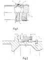
- the illustrated embodiment comprises a tubular body 1, which may be a backshell adaptor to support a bundle of electrical cables that enter it from the rear and terminate in an electrical connector supported within the front end of the backshell.
- a coupling nut 2 is rotatably mounted on the front end of the body 1 and is held captive longitudinally thereon by a circlip 3 engaging respective annular grooves in the cooperating surfaces of the nut and body. The nut 2 projects longitudinally beyond the end of the body 1 and is threaded internally for engagement with the aforesaid electrical connector when in use.
- a locking ring or collar 4 Adjacent to the rear of the coupling nut 2, a locking ring or collar 4 is mounted on the body 1, and is formed with a set of inwardly projecting lugs 5 which engage respective longitudinally, extending grooves 6 in an annular collar 9 formed on the outer surface of the body so as to guide the locking ring 4 longitudinally over a short section of its length between the rear face of the nut 2 and an outwardly projecting annular flange 7 around the periphery of the body 1.
- a spring washer 8 is located between the flange 7 and rear face of the locking ring 4 and acts to urge the latter to a locking position in engagement with the rear face of the coupling nut 2. as shown in Figure 1.
- the rear annular face of the coupling nut 2 is formed with teeth 10 that project longitudinally of the body 1 towards the locking ring 4, and the adjacent annular face of the locking ring 4 is formed with teeth 11 that project longitudinally of the body 1 towards the coupling nut 2 so as to cooperate with the teeth 10 on the latter.
- These teeth 10 and 11 run in a sawtooth form around the full annular length of the faces, respective with corresponding alternating inclined and circumferentially abutting edges so that the teeth can ride over one another with a ratchet action when the nut 2 is rotated in one sense to secure an electrical connector to the body 1, and lock together circumferentially to prevent rotation of the nut 2 in the opposite sense that would release said electrical connector.
- the coupling nut 2 can be rotated to release said electrical connector. Furthermore, the arrangement of the teeth 10,11 is such that an interengaging locking action is maintained even if the locking ring 4 is tilted accidentally on the body 1, the teeth 10,11 disengaging on one side of the body, but remaining in engagement on the other of the body.
- the inwardly projecting lugs 5 and collar 9 are dimensioned longitudinally so that the lugs 5 disengage the grooves 6 and are located in the annular groove 12 between the flange 7 and collar 9, as shown in Figure 3, whereupon the ring 4 can be rotated to a position in which the lugs 5 are out of alignment with the grooves 6. The ring 4 can then be released and will be retained longitudinally by engagement of the lugs 5 with the adjacent side wall of the collar 9 through the spring action of the washer 8.
- Annular recesses 14 and 15 are provided in the adjacent faces of the flange 7 and locking ring 4 to accommodate the spring washer 8 when the locking ring is in the unlocking position.
- the groove 12 to the rear of the collar 9 is coloured green or blue so as to indicate when the locking ring 4 is in the locking position. and a shallow groove 13 forward of the collar 9 is coloured red so that it is clearly visible when the locking ring is in the unlocking position, and thereby serving as a warning that the coupling nut 2 is not locked.
- the outer circumferential surfaces of the coupling nut 2 and locking ring 4 are each textured to assist gripping and rotation, this being especially important in oily environments. Also, the texturing used, whether knurling or ribs, are preferably different in each case to assist tactile differentiation between the two components in question.
- the outer diameters of the coupling nut 2 and locking ring 4 are preferably different so as to assist selective operation of one or the other and avoid accidental operation of either member.
- accidental rotation of the locking ring 4 by a tool engaging the coupling nut 2 could damage the lugs 5 of the former so that it is no longer effective.
- This can be avoided by making the locking ring 4 of smaller diameter than the coupling nut 2. as shown in the drawings, but equally the locking ring 4 could be made significantly larger in diameter to avoid the same problem.
- a special tool might be provided to operate the locking ring.
- the number of teeth can be freely chosen to select the amount of rotation that separates each locking position. It has been found that a resolution of 10° or so between each locking position maintains good electrical connection between the opposing parts of the coupling. This requires the provision of 30 or more teeth on the nut and locking ring.
- Drain holes may be provided in the region of the spring washer 8 to allow the escape of moisture due to condensation.
- the short faces of the teeth may be inclined with respect to the longitudinal axis of the connector by between substantially 0 and 5° in an undercut manner to further enhance the resistance of the locking ring to unintentional disengagement due to extreme vibration.
Landscapes
- Details Of Connecting Devices For Male And Female Coupling (AREA)
- Quick-Acting Or Multi-Walled Pipe Joints (AREA)
Description
Claims (8)
- A locking coupling comprising: a body (1) adapted for connection to a separate body; a coupling collar (2) rotatably mounted on said body and adapted to cooperate with said separate body to hold it in axial connection with said body, said coupling collar being rotatable in a locking sense to hold said body (1) and said separate body together, and in a release sense to release said body from said separate body; characterised by a locking collar mounted on said body and longitudinally movable with respect to the coupling collar between locking and unlocking positions; bias means (8) that urge the locking collar (4) towards the locking position; and locking formations (10,11) on the locking collar and coupling collar; and in that the locking collar (4) is restrained from rotating when it is at the locking position and in that the locking formations on the coupling collar interengage axially with those on the locking collar when the locking collar is moved to the locking position so as to restrain the coupling collar against rotation in the release sense on said body (1).
- A locking coupling as claimed in claim 1 in which the locking collar (2) is retained in the unlocking position by retention formations (5,9) on the locking collar and body that interengage longitudinally.
- A locking coupling as claimed in claim 2 in which the retention formations comprise keying means that guide the locking collar longitudinally on the body and allow rotation of the locking collar on the body only in the unlocking position, when the keying means then cooperate longitudinally to retain the locking collar in the unlocking position.
- A locking coupling as claimed in any one of the preceding claims in which the locking collar (4) is held captive longitudinally on the body by the coupling collar (2), and the coupling collar in turn is held captive on the body by a separate fastener (3).
- A locking coupling as claimed in claim 4 in which the separate fastener (3) comprises an internal circlip.
- A locking coupling as claimed in any one of the preceding claims in which the locking formations comprise axially extending teeth (10,11).
- A locking coupling as claimed in claim 6 in which the teeth have a tooth form so as to restrain the coupling collar against rotation in one sense which would otherwise allow uncoupling of said separate body.
- A locking coupling as claimed in any one of the preceding claims in which indicator means on said body is covered by the locking collar and only exposed as a warning when the locking collar is in the unlocking position.
Applications Claiming Priority (3)
| Application Number | Priority Date | Filing Date | Title |
|---|---|---|---|
| GB9506700A GB2299460B (en) | 1995-03-31 | 1995-03-31 | Locking coupling |
| GB9506700 | 1995-03-31 | ||
| PCT/GB1996/000779 WO1996030970A1 (en) | 1995-03-31 | 1996-04-01 | Locking coupling |
Publications (2)
| Publication Number | Publication Date |
|---|---|
| EP0818064A1 EP0818064A1 (en) | 1998-01-14 |
| EP0818064B1 true EP0818064B1 (en) | 1999-12-29 |
Family
ID=10772280
Family Applications (1)
| Application Number | Title | Priority Date | Filing Date |
|---|---|---|---|
| EP96908256A Expired - Lifetime EP0818064B1 (en) | 1995-03-31 | 1996-04-01 | Locking coupling |
Country Status (9)
| Country | Link |
|---|---|
| US (1) | US5957716A (en) |
| EP (1) | EP0818064B1 (en) |
| JP (1) | JPH11502970A (en) |
| CA (1) | CA2216403A1 (en) |
| DE (1) | DE69605903T2 (en) |
| ES (1) | ES2140833T3 (en) |
| GB (1) | GB2299460B (en) |
| MX (1) | MX9707413A (en) |
| WO (1) | WO1996030970A1 (en) |
Families Citing this family (90)
| Publication number | Priority date | Publication date | Assignee | Title |
|---|---|---|---|---|
| GB9802777D0 (en) * | 1998-02-11 | 1998-04-08 | Gore W L & Ass Uk | Connector assembly |
| DE19923386C1 (en) * | 1999-05-21 | 2001-01-18 | Framatome Connectors Int | Electrical connector, in particular for automotive applications |
| US6123563A (en) * | 1999-09-08 | 2000-09-26 | Amphenol Corporation | Anti-decoupling arrangement for an electrical connector |
| EP1617524A1 (en) * | 2004-07-14 | 2006-01-18 | Coninvers Elektrotechnische Bauelemente GmbH | Electrical connector |
| US20060110977A1 (en) * | 2004-11-24 | 2006-05-25 | Roger Matthews | Connector having conductive member and method of use thereof |
| US8157589B2 (en) | 2004-11-24 | 2012-04-17 | John Mezzalingua Associates, Inc. | Connector having a conductively coated member and method of use thereof |
| US7347458B2 (en) * | 2005-01-14 | 2008-03-25 | C. R. Bard, Inc. | Locking luer fitting |
| US7114990B2 (en) | 2005-01-25 | 2006-10-03 | Corning Gilbert Incorporated | Coaxial cable connector with grounding member |
| CN2847596Y (en) * | 2005-11-04 | 2006-12-13 | 西安科耐特科技有限责任公司 | Quick insert self locking radio frequency coaxial connector |
| JP4756204B2 (en) * | 2007-08-31 | 2011-08-24 | 丸一株式会社 | Nut for piping |
| US9106012B2 (en) * | 2008-05-30 | 2015-08-11 | Itt Manufacturing Enterprises, Inc. | Antirotation coupling for connector |
| US8075337B2 (en) | 2008-09-30 | 2011-12-13 | Belden Inc. | Cable connector |
| US7845963B2 (en) * | 2008-10-21 | 2010-12-07 | Itt Manufacturing Enterprises, Inc. | Axial anti-rotation coupling |
| US7980781B2 (en) | 2009-02-20 | 2011-07-19 | Charles Edward Trice | Self locking mast assembly and method of making |
| US8025518B2 (en) | 2009-02-24 | 2011-09-27 | Corning Gilbert Inc. | Coaxial connector with dual-grip nut |
| US8029315B2 (en) | 2009-04-01 | 2011-10-04 | John Mezzalingua Associates, Inc. | Coaxial cable connector with improved physical and RF sealing |
| US7824216B2 (en) | 2009-04-02 | 2010-11-02 | John Mezzalingua Associates, Inc. | Coaxial cable continuity connector |
| US7892005B2 (en) | 2009-05-19 | 2011-02-22 | John Mezzalingua Associates, Inc. | Click-tight coaxial cable continuity connector |
| US9017101B2 (en) | 2011-03-30 | 2015-04-28 | Ppc Broadband, Inc. | Continuity maintaining biasing member |
| US8573996B2 (en) | 2009-05-22 | 2013-11-05 | Ppc Broadband, Inc. | Coaxial cable connector having electrical continuity member |
| US8444445B2 (en) | 2009-05-22 | 2013-05-21 | Ppc Broadband, Inc. | Coaxial cable connector having electrical continuity member |
| US8287320B2 (en) | 2009-05-22 | 2012-10-16 | John Mezzalingua Associates, Inc. | Coaxial cable connector having electrical continuity member |
| US9570845B2 (en) | 2009-05-22 | 2017-02-14 | Ppc Broadband, Inc. | Connector having a continuity member operable in a radial direction |
| US7905741B1 (en) | 2009-11-06 | 2011-03-15 | Amphenol Corporation | Anti-vibration connector coupling with an axially movable ratchet ring |
| US7914311B1 (en) * | 2009-11-06 | 2011-03-29 | Amphenol Corporation | Anti-vibration connector coupling with an axially movable ratchet ring and a collar |
| US8272893B2 (en) | 2009-11-16 | 2012-09-25 | Corning Gilbert Inc. | Integrally conductive and shielded coaxial cable connector |
| TWI549386B (en) | 2010-04-13 | 2016-09-11 | 康寧吉伯特公司 | Coaxial connector with inhibited ingress and improved grounding |
| IL213239A (en) * | 2010-06-08 | 2017-02-28 | Amphenol Corp | Connector coupling |
| FR2961883B1 (en) * | 2010-06-24 | 2014-01-17 | Souriau | REINFORCED LOCKING SCREW CONNECTOR |
| US8079860B1 (en) | 2010-07-22 | 2011-12-20 | John Mezzalingua Associates, Inc. | Cable connector having threaded locking collet and nut |
| US8152551B2 (en) | 2010-07-22 | 2012-04-10 | John Mezzalingua Associates, Inc. | Port seizing cable connector nut and assembly |
| US8113879B1 (en) | 2010-07-27 | 2012-02-14 | John Mezzalingua Associates, Inc. | One-piece compression connector body for coaxial cable connector |
| US8888526B2 (en) | 2010-08-10 | 2014-11-18 | Corning Gilbert, Inc. | Coaxial cable connector with radio frequency interference and grounding shield |
| US8167636B1 (en) | 2010-10-15 | 2012-05-01 | John Mezzalingua Associates, Inc. | Connector having a continuity member |
| US8167646B1 (en) | 2010-10-18 | 2012-05-01 | John Mezzalingua Associates, Inc. | Connector having electrical continuity about an inner dielectric and method of use thereof |
| US8167635B1 (en) | 2010-10-18 | 2012-05-01 | John Mezzalingua Associates, Inc. | Dielectric sealing member and method of use thereof |
| US8323053B2 (en) | 2010-10-18 | 2012-12-04 | John Mezzalingua Associates, Inc. | Connector having a constant contact nut |
| US8075338B1 (en) | 2010-10-18 | 2011-12-13 | John Mezzalingua Associates, Inc. | Connector having a constant contact post |
| TWI558022B (en) | 2010-10-27 | 2016-11-11 | 康寧吉伯特公司 | Push-on cable connector with a coupler and retention and release mechanism |
| US8337229B2 (en) | 2010-11-11 | 2012-12-25 | John Mezzalingua Associates, Inc. | Connector having a nut-body continuity element and method of use thereof |
| US8414322B2 (en) | 2010-12-14 | 2013-04-09 | Ppc Broadband, Inc. | Push-on CATV port terminator |
| US8398421B2 (en) | 2011-02-01 | 2013-03-19 | John Mezzalingua Associates, Inc. | Connector having a dielectric seal and method of use thereof |
| US8157588B1 (en) | 2011-02-08 | 2012-04-17 | Belden Inc. | Cable connector with biasing element |
| US8342879B2 (en) | 2011-03-25 | 2013-01-01 | John Mezzalingua Associates, Inc. | Coaxial cable connector |
| US8465322B2 (en) | 2011-03-25 | 2013-06-18 | Ppc Broadband, Inc. | Coaxial cable connector |
| US8366481B2 (en) | 2011-03-30 | 2013-02-05 | John Mezzalingua Associates, Inc. | Continuity maintaining biasing member |
| US8388377B2 (en) | 2011-04-01 | 2013-03-05 | John Mezzalingua Associates, Inc. | Slide actuated coaxial cable connector |
| US8348697B2 (en) | 2011-04-22 | 2013-01-08 | John Mezzalingua Associates, Inc. | Coaxial cable connector having slotted post member |
| US9203167B2 (en) | 2011-05-26 | 2015-12-01 | Ppc Broadband, Inc. | Coaxial cable connector with conductive seal |
| US9711917B2 (en) | 2011-05-26 | 2017-07-18 | Ppc Broadband, Inc. | Band spring continuity member for coaxial cable connector |
| US8758050B2 (en) | 2011-06-10 | 2014-06-24 | Hiscock & Barclay LLP | Connector having a coupling member for locking onto a port and maintaining electrical continuity |
| US8591244B2 (en) | 2011-07-08 | 2013-11-26 | Ppc Broadband, Inc. | Cable connector |
| US9190744B2 (en) | 2011-09-14 | 2015-11-17 | Corning Optical Communications Rf Llc | Coaxial cable connector with radio frequency interference and grounding shield |
| US20130072057A1 (en) | 2011-09-15 | 2013-03-21 | Donald Andrew Burris | Coaxial cable connector with integral radio frequency interference and grounding shield |
| US9147955B2 (en) | 2011-11-02 | 2015-09-29 | Ppc Broadband, Inc. | Continuity providing port |
| US9136654B2 (en) | 2012-01-05 | 2015-09-15 | Corning Gilbert, Inc. | Quick mount connector for a coaxial cable |
| US9407016B2 (en) | 2012-02-22 | 2016-08-02 | Corning Optical Communications Rf Llc | Coaxial cable connector with integral continuity contacting portion |
| US8579644B2 (en) | 2012-03-13 | 2013-11-12 | Amphenol Corporation | Anti-vibration connector coupling with disengagement feature |
| US9287659B2 (en) | 2012-10-16 | 2016-03-15 | Corning Optical Communications Rf Llc | Coaxial cable connector with integral RFI protection |
| US9147963B2 (en) | 2012-11-29 | 2015-09-29 | Corning Gilbert Inc. | Hardline coaxial connector with a locking ferrule |
| US9708865B2 (en) * | 2012-12-13 | 2017-07-18 | Vetco Gray Inc. | Ratcheting anti-rotation lock for threaded connectors |
| US9153911B2 (en) | 2013-02-19 | 2015-10-06 | Corning Gilbert Inc. | Coaxial cable continuity connector |
| IL231455A0 (en) | 2013-03-15 | 2014-08-31 | Amphenol Corp | Positive locking connector coupling |
| US9397441B2 (en) * | 2013-03-15 | 2016-07-19 | Cinch Connections, Inc. | Connector with anti-decoupling mechanism |
| US9172154B2 (en) | 2013-03-15 | 2015-10-27 | Corning Gilbert Inc. | Coaxial cable connector with integral RFI protection |
| US9130281B2 (en) | 2013-04-17 | 2015-09-08 | Ppc Broadband, Inc. | Post assembly for coaxial cable connectors |
| US10290958B2 (en) | 2013-04-29 | 2019-05-14 | Corning Optical Communications Rf Llc | Coaxial cable connector with integral RFI protection and biasing ring |
| EP3000154B1 (en) | 2013-05-20 | 2019-05-01 | Corning Optical Communications RF LLC | Coaxial cable connector with integral rfi protection |
| US9548557B2 (en) | 2013-06-26 | 2017-01-17 | Corning Optical Communications LLC | Connector assemblies and methods of manufacture |
| GB2518157A (en) * | 2013-09-11 | 2015-03-18 | Mini Cam Ltd | A Connector |
| JP6358490B2 (en) * | 2013-09-30 | 2018-07-18 | 日立金属株式会社 | Pipe fitting |
| US9048599B2 (en) | 2013-10-28 | 2015-06-02 | Corning Gilbert Inc. | Coaxial cable connector having a gripping member with a notch and disposed inside a shell |
| US9528646B2 (en) | 2014-05-02 | 2016-12-27 | Itt Manufacturing Enterprises, Llc | Locking and ratcheting connector |
| US9559457B2 (en) | 2014-07-16 | 2017-01-31 | Amphenol Corporation | Anti-vibration coupling device |
| WO2016073309A1 (en) | 2014-11-03 | 2016-05-12 | Corning Optical Communications Rf Llc | Coaxial cable connector with integral rfi protection |
| US9781886B1 (en) * | 2014-12-19 | 2017-10-10 | Orbit Irrigation Products, Inc. | Hand-securable sprinkler fitting |
| US10033122B2 (en) | 2015-02-20 | 2018-07-24 | Corning Optical Communications Rf Llc | Cable or conduit connector with jacket retention feature |
| US9590287B2 (en) | 2015-02-20 | 2017-03-07 | Corning Optical Communications Rf Llc | Surge protected coaxial termination |
| US10211547B2 (en) | 2015-09-03 | 2019-02-19 | Corning Optical Communications Rf Llc | Coaxial cable connector |
| US9525220B1 (en) | 2015-11-25 | 2016-12-20 | Corning Optical Communications LLC | Coaxial cable connector |
| US10480696B2 (en) | 2015-12-01 | 2019-11-19 | Forum Us, Inc. | Locking collar quick union connection |
| EP3211726B1 (en) * | 2016-02-23 | 2021-05-05 | Siemens Energy Global GmbH & Co. KG | Connector unit comprising two connector parts and method for operating such connector unit |
| US9666973B1 (en) | 2016-06-10 | 2017-05-30 | Amphenol Corporation | Self-locking connector coupling |
| US10756482B2 (en) | 2016-09-20 | 2020-08-25 | Itt Manufacturing Enterprises Llc | Torque-limiting couplings |
| US10344896B2 (en) * | 2017-02-10 | 2019-07-09 | Dril-Quip, Inc. | Vertical ratcheting anti-rotation device |
| DE202018102532U1 (en) | 2018-05-07 | 2018-05-22 | Neutrik Ag | connector part |
| US11955748B2 (en) | 2020-08-13 | 2024-04-09 | Amphenol Corporation | Connector coupling |
| US12034264B2 (en) | 2021-03-31 | 2024-07-09 | Corning Optical Communications Rf Llc | Coaxial cable connector assemblies with outer conductor engagement features and methods for using the same |
| CN114962814B (en) * | 2022-05-23 | 2024-09-03 | 青岛众凯食品有限公司 | Concentration regulator for preparing food additives and regulation method |
| CN118431833B (en) * | 2024-07-05 | 2024-08-30 | 武汉德泰纳新能源技术有限公司 | New energy automobile socket electronic lock that charges |
Family Cites Families (7)
| Publication number | Priority date | Publication date | Assignee | Title |
|---|---|---|---|---|
| US2829358A (en) * | 1956-06-15 | 1958-04-01 | Testori Giglio | Connectors with coupling lock |
| US3971614A (en) * | 1972-11-03 | 1976-07-27 | Akzona Incorporated | Electrical connector with means for maintaining a connected condition |
| DE2840728C2 (en) * | 1978-09-19 | 1980-09-04 | Georg Dipl.-Ing. Dr.-Ing. 8152 Feldkirchen-Westerham Spinner | RF coaxial connector |
| FR2563949A1 (en) * | 1984-05-07 | 1985-11-08 | Deutsch Co | Visual indication (tell-tale) connector, for electrical cables |
| US4648671A (en) * | 1986-05-29 | 1987-03-10 | Allied Corporation | Self locking coupling device |
| FR2696049B1 (en) * | 1992-09-21 | 1994-11-18 | Souriau & Cie | Electrical connector with threaded ring and preponderant locking. |
| CA2128172C (en) * | 1993-08-27 | 1997-05-13 | Alan R. Miklos | Self-seating connector adapter |
-
1995
- 1995-03-31 GB GB9506700A patent/GB2299460B/en not_active Revoked
-
1996
- 1996-04-01 DE DE69605903T patent/DE69605903T2/en not_active Expired - Fee Related
- 1996-04-01 ES ES96908256T patent/ES2140833T3/en not_active Expired - Lifetime
- 1996-04-01 JP JP8529095A patent/JPH11502970A/en not_active Abandoned
- 1996-04-01 EP EP96908256A patent/EP0818064B1/en not_active Expired - Lifetime
- 1996-04-01 WO PCT/GB1996/000779 patent/WO1996030970A1/en not_active Ceased
- 1996-04-01 CA CA002216403A patent/CA2216403A1/en not_active Abandoned
- 1996-04-01 US US08/860,308 patent/US5957716A/en not_active Expired - Fee Related
-
1997
- 1997-09-29 MX MX9707413A patent/MX9707413A/en unknown
Also Published As
| Publication number | Publication date |
|---|---|
| GB2299460A (en) | 1996-10-02 |
| DE69605903D1 (en) | 2000-02-03 |
| CA2216403A1 (en) | 1996-10-03 |
| EP0818064A1 (en) | 1998-01-14 |
| GB2299460B (en) | 1998-12-30 |
| MX9707413A (en) | 1998-07-31 |
| GB2299460A8 (en) | 1996-10-14 |
| JPH11502970A (en) | 1999-03-09 |
| ES2140833T3 (en) | 2000-03-01 |
| GB9506700D0 (en) | 1995-05-24 |
| US5957716A (en) | 1999-09-28 |
| WO1996030970A1 (en) | 1996-10-03 |
| DE69605903T2 (en) | 2000-07-27 |
Similar Documents
| Publication | Publication Date | Title |
|---|---|---|
| US5957716A (en) | Locking coupling connector | |
| US5653605A (en) | Locking coupling | |
| EP0921604B1 (en) | Device for clamping the cable in electrical outlets or plugs | |
| US4595251A (en) | Coupling mechanism for connectors | |
| US3971614A (en) | Electrical connector with means for maintaining a connected condition | |
| US3314696A (en) | Quick connect coupling | |
| US4655482A (en) | Tube coupling device | |
| GB2526369B (en) | Electrical connector | |
| US6086400A (en) | Self-locking cable connector coupling | |
| US5934709A (en) | Fluid couplings | |
| US4168921A (en) | Cable connector or terminator | |
| US5211576A (en) | Strain relief cable clamp | |
| CN1108001C (en) | Device for clamping cable in electrical outlets or plugs | |
| EP0589589B1 (en) | Connector assemblies | |
| US7181999B1 (en) | Tool for driving coaxial cable connectors | |
| US4208082A (en) | Quick-release electrical connectors | |
| GB2055255A (en) | Locking means for two-part electrical connector | |
| US4955749A (en) | Swivel connector | |
| WO1991003676A1 (en) | Quick connect coupling with twist release | |
| US20240241323A1 (en) | Cable connector assembly | |
| US4500154A (en) | Electrical connector assembly having an anti-decoupling device | |
| CA2164924C (en) | Electrical wiring device with conduit clamping mechanism | |
| US4717351A (en) | Redundant electrical connector release | |
| GB1587233A (en) | Clamp for conductor of an overhead electricity transmission line | |
| GB2335090A (en) | Connector assembly |
Legal Events
| Date | Code | Title | Description |
|---|---|---|---|
| PUAI | Public reference made under article 153(3) epc to a published international application that has entered the european phase |
Free format text: ORIGINAL CODE: 0009012 |
|
| 17P | Request for examination filed |
Effective date: 19970904 |
|
| AK | Designated contracting states |
Kind code of ref document: A1 Designated state(s): DE ES FR GB IT |
|
| 17Q | First examination report despatched |
Effective date: 19980824 |
|
| GRAG | Despatch of communication of intention to grant |
Free format text: ORIGINAL CODE: EPIDOS AGRA |
|
| GRAG | Despatch of communication of intention to grant |
Free format text: ORIGINAL CODE: EPIDOS AGRA |
|
| GRAH | Despatch of communication of intention to grant a patent |
Free format text: ORIGINAL CODE: EPIDOS IGRA |
|
| GRAH | Despatch of communication of intention to grant a patent |
Free format text: ORIGINAL CODE: EPIDOS IGRA |
|
| GRAA | (expected) grant |
Free format text: ORIGINAL CODE: 0009210 |
|
| AK | Designated contracting states |
Kind code of ref document: B1 Designated state(s): DE ES FR GB IT |
|
| REF | Corresponds to: |
Ref document number: 69605903 Country of ref document: DE Date of ref document: 20000203 |
|
| ITF | It: translation for a ep patent filed | ||
| REG | Reference to a national code |
Ref country code: ES Ref legal event code: FG2A Ref document number: 2140833 Country of ref document: ES Kind code of ref document: T3 |
|
| ET | Fr: translation filed | ||
| PLBE | No opposition filed within time limit |
Free format text: ORIGINAL CODE: 0009261 |
|
| STAA | Information on the status of an ep patent application or granted ep patent |
Free format text: STATUS: NO OPPOSITION FILED WITHIN TIME LIMIT |
|
| 26N | No opposition filed | ||
| REG | Reference to a national code |
Ref country code: GB Ref legal event code: IF02 |
|
| PGFP | Annual fee paid to national office [announced via postgrant information from national office to epo] |
Ref country code: GB Payment date: 20030107 Year of fee payment: 8 |
|
| PGFP | Annual fee paid to national office [announced via postgrant information from national office to epo] |
Ref country code: FR Payment date: 20030131 Year of fee payment: 8 |
|
| PGFP | Annual fee paid to national office [announced via postgrant information from national office to epo] |
Ref country code: ES Payment date: 20030203 Year of fee payment: 8 |
|
| PGFP | Annual fee paid to national office [announced via postgrant information from national office to epo] |
Ref country code: DE Payment date: 20030324 Year of fee payment: 8 |
|
| PG25 | Lapsed in a contracting state [announced via postgrant information from national office to epo] |
Ref country code: GB Free format text: LAPSE BECAUSE OF NON-PAYMENT OF DUE FEES Effective date: 20040401 |
|
| PG25 | Lapsed in a contracting state [announced via postgrant information from national office to epo] |
Ref country code: ES Free format text: LAPSE BECAUSE OF NON-PAYMENT OF DUE FEES Effective date: 20040402 |
|
| PG25 | Lapsed in a contracting state [announced via postgrant information from national office to epo] |
Ref country code: DE Free format text: LAPSE BECAUSE OF NON-PAYMENT OF DUE FEES Effective date: 20041103 |
|
| GBPC | Gb: european patent ceased through non-payment of renewal fee | ||
| PG25 | Lapsed in a contracting state [announced via postgrant information from national office to epo] |
Ref country code: FR Free format text: LAPSE BECAUSE OF NON-PAYMENT OF DUE FEES Effective date: 20041231 |
|
| REG | Reference to a national code |
Ref country code: FR Ref legal event code: ST |
|
| PG25 | Lapsed in a contracting state [announced via postgrant information from national office to epo] |
Ref country code: IT Free format text: LAPSE BECAUSE OF NON-PAYMENT OF DUE FEES Effective date: 20050401 |
|
| REG | Reference to a national code |
Ref country code: ES Ref legal event code: FD2A Effective date: 20040402 |