EP0817690B1 - Method and arrangement for conveying moulds with castings therein - Google Patents
Method and arrangement for conveying moulds with castings therein Download PDFInfo
- Publication number
- EP0817690B1 EP0817690B1 EP96909073A EP96909073A EP0817690B1 EP 0817690 B1 EP0817690 B1 EP 0817690B1 EP 96909073 A EP96909073 A EP 96909073A EP 96909073 A EP96909073 A EP 96909073A EP 0817690 B1 EP0817690 B1 EP 0817690B1
- Authority
- EP
- European Patent Office
- Prior art keywords
- conveyor
- mould
- moulds
- castings
- string
- Prior art date
- Legal status (The legal status is an assumption and is not a legal conclusion. Google has not performed a legal analysis and makes no representation as to the accuracy of the status listed.)
- Expired - Lifetime
Links
- 238000005266 casting Methods 0.000 title claims abstract description 79
- 238000000034 method Methods 0.000 title claims abstract description 20
- 238000000605 extraction Methods 0.000 claims description 26
- 230000001965 increasing effect Effects 0.000 claims description 6
- 238000006073 displacement reaction Methods 0.000 claims description 5
- 230000000063 preceeding effect Effects 0.000 claims 2
- 238000001816 cooling Methods 0.000 abstract description 38
- 239000000428 dust Substances 0.000 abstract description 7
- 238000004519 manufacturing process Methods 0.000 abstract description 3
- 239000000463 material Substances 0.000 description 10
- 239000004576 sand Substances 0.000 description 10
- 230000007547 defect Effects 0.000 description 4
- 230000000694 effects Effects 0.000 description 4
- 238000009413 insulation Methods 0.000 description 4
- 238000007711 solidification Methods 0.000 description 4
- 230000008023 solidification Effects 0.000 description 4
- 238000010276 construction Methods 0.000 description 3
- 230000001360 synchronised effect Effects 0.000 description 3
- 238000010438 heat treatment Methods 0.000 description 2
- XLYOFNOQVPJJNP-UHFFFAOYSA-N water Substances O XLYOFNOQVPJJNP-UHFFFAOYSA-N 0.000 description 2
- 230000006978 adaptation Effects 0.000 description 1
- 230000003190 augmentative effect Effects 0.000 description 1
- 239000011230 binding agent Substances 0.000 description 1
- 238000009833 condensation Methods 0.000 description 1
- 230000005494 condensation Effects 0.000 description 1
- 238000005516 engineering process Methods 0.000 description 1
- 238000001704 evaporation Methods 0.000 description 1
- 239000012634 fragment Substances 0.000 description 1
- 239000012535 impurity Substances 0.000 description 1
- 230000001939 inductive effect Effects 0.000 description 1
- 239000007788 liquid Substances 0.000 description 1
- 239000002245 particle Substances 0.000 description 1
- 239000000843 powder Substances 0.000 description 1
- 238000000926 separation method Methods 0.000 description 1
- 239000007787 solid Substances 0.000 description 1
- 238000002604 ultrasonography Methods 0.000 description 1
- 238000011144 upstream manufacturing Methods 0.000 description 1
Images


Classifications
-
- B—PERFORMING OPERATIONS; TRANSPORTING
- B22—CASTING; POWDER METALLURGY
- B22C—FOUNDRY MOULDING
- B22C11/00—Moulding machines characterised by the relative arrangement of the parts of same
- B22C11/10—Moulding machines characterised by the relative arrangement of the parts of same with one or more flasks forming part of the machine, from which only the sand moulds made by compacting are removed
-
- B—PERFORMING OPERATIONS; TRANSPORTING
- B22—CASTING; POWDER METALLURGY
- B22D—CASTING OF METALS; CASTING OF OTHER SUBSTANCES BY THE SAME PROCESSES OR DEVICES
- B22D33/00—Equipment for handling moulds
- B22D33/005—Transporting flaskless moulds
-
- B—PERFORMING OPERATIONS; TRANSPORTING
- B22—CASTING; POWDER METALLURGY
- B22D—CASTING OF METALS; CASTING OF OTHER SUBSTANCES BY THE SAME PROCESSES OR DEVICES
- B22D47/00—Casting plants
- B22D47/02—Casting plants for both moulding and casting
Definitions
- the present invention relates to a method for conveying moulds with castings therein, said method being of the kind set forth in the preamble of claim 1.
- the second conveyor referred to is normally of a relatively light construction.
- the moulds When making castings by pouring moulds with vertical parting surfaces, the moulds will normally be advanced along the pouring track on a precision conveyor, e.g. of the kind described in the DK patent publications Nos. 119,373 and 127,494 and DE-A-24 04 907; in this manner, the moulds or mould parts are placed in mutual abutment in a highly accurate manner, and this accuracy is maintained during the steps of pouring and solidification.
- the moulds may be transferred to a conveyor of the kind described in DK-patent publication No. 138,840, making it possible to reduce the total frictional resistance against the movement of the moulds.
- the moulds are frequently transferred at a relatively early stage in the process from the precision conveyor to a second conveyor producing less frictional resistance than the precision conveyor.
- This second conveyor may possibly be constituted by an endless belt.
- the transfer to the second conveyor it must be ensured, either that the casting is sufficiently cooled to avoid the occurrence of cooling defects or deformations, or that the individual moulds are transferred in a manner preventing mutual displacements of the mould parts, possibly being the cause of deformations or cooling defects, respectively. Because of these relationships, the string of moulds will normally be transferred as a solid body through the second conveyor and advanced - still undivided - on the latter, until the castings have been cooled sufficiently, eventually to reach an extraction station.
- An alternative to conveying the string of moulds as a continuous string to the extraction station is based on the use of devices to divide or break open the moulds in the mould string, e.g. of the kind shown in DK-B-129,397, in which such a device removes the central part of the moulds together with the castings.
- This alternative will, however, require the use of complicated equipment, the latter frequently having to be adapted to the particular castings being made and the particular moulds being used at any moment, especially when there is a change in the dimensions.
- such an intermediate station will produce dust and fragments to be accounted for, as they can constitute a health risk and contribute to increased wear on moving parts.
- the string of moulds will be advanced in the form of a continuous string on the second conveyor until the castings are cooled sufficiently for the extraction step.
- the second conveyor consists of flexible material incapable of withstanding high temperatures, such as e.g. is the case with endless belts of rubber or plastic material, it must be ensured, either that the castings do not come into contact with the conveyor belt during the extraction, or that the castings are cooled to a temperature not causing damage to the conveyor belt, the latter temperature frequently lying far below the temperature of solidification of the castings, thus requiring a disproportionately long cooling time on the conveyor belt.
- a previously known automatic casting machine of the kind referred to above operates in the following manner.
- the moulds or mould parts are produced in a mould-making station, from which they are conveyed in the form of a closely packed string of moulds by a precision conveyor along a track to a pouring station, in which liquid casting material is poured into the casting cavities formed between the closely juxtaposed moulds or mould parts.
- the moulds or mould parts now containing the casting material having been poured into them, are advanced, still in the form of a continuous string, along the casting track, during which the cooling is initiated in a cooling section.
- some plants are provided with a divided cooling section, in which the string of moulds is transferred to a driven conventional conveyor being synchronized with the precision conveying of the string of moulds, so that the latter is advanced without substantial displacement between the moulds occurring.
- the cooling section may, however, become very long, especially when producing large castings, because the moulds act as heat insulation.
- the prior art has comprised attempts to shorten the cooling time by during the cooling step removing parts of the moulds or extracting the castings with a surrounding part of the moulds. This will, however, frequently require specially constructed apparatus adapted to the particular castings being made, and is also likely to produce large quantities of dust.
- the purpose of the previously known second conveyor placed in extension of a precision conveyor has predominantly been to reduce the sand adhesion on the precision conveyor, and this has - to the extent that cooling is also provided during the movement on a conventional conveyor - resulted in relatively long conveying distances and cooling times, possibly also a relatively large quantity of "burnt-out" binder in the mould material.
- EP-A-0,385,245 discloses an apparatus for grouping and synchronizing articles arriving on a convey or belt for feeding a wrapping or boxing machine.
- EP-A-0,385,245 has however no connection to foundry technology.
- Document JP-91959/89 discloses an automatic casting machine in which the moulds on the second conveyor are separated from one another by an interspace, thus improving cooling.
- the interspace is achieved by controlling the first precision conveyor so as to transfer a mould exactly when the continuously running second conveyor has advanced the required distance. Thus, any interruption in the production of the moulds at the mould making station or during the transport on the first conveyor will lead to deviations in the interspace.
- the present invention also relates to an arrangement for carrying out the method of the invention.
- This arrangement is of the kind set forth in the preamble of claim 7, and, according to the present invention, it also exhibits the features set forth in the characterizing clause of this claim 7.
- the present invention provides a number of advantages based upon the use of simple means.
- the cooling is intensified, and it may be controlled by increasing the surface of the individual moulds and allowing air to come into contact with the castings, made possible by the mutual separation of the moulds in the string of moulds. This also makes it possible to reduce the quantity of "burnt-out" sand in the mould, as the cooling of the moulds themselves is also intensified. Since it is only the distance, through which the second conveyor moves for each transfer step or cycle, that will possibly be altered when changing the size of the mould or casting, an adaptation to different castings will also be very simple.
- the invention is especially suitable for use when the temperature, to which the castings are to be cooled, depends on other parameters than the solidification temperature; this may be the case, when the castings at the solidification temperature still have a temperature capable of causing damage to other parts, such as a conveyor belt of a material not capable of withstanding high temperature, because the invention provides the possibility of opening the moulds and at the same time use them as heat insulation relative to the surrounding parts, such as the conveyor belt.
- the present invention provides the possibility of extracting the castings using simple means, since it is possible for a gripping device to engage the castings through the opening between the moulds without the necessity of breaking or destroying the latter. This makes it possible to simplify the construction of the extraction station and to reduce the production of dust.
- the invention makes it possible to use conveyors not specially constructed with a view to precision and temperature resistance, thus simplifying the construction.
- the mould having been overturned will protect the conveyor belt against unintentional heating. This is especially of advantage during the extraction step, such as set forth in claim 6.
- the method of the invention may advantageously be carried out with an arrangement of the kind set forth in claim 7, thus using one second conveyor.
- the conveyor may advantageously be constituted by a conveyor belt.
- this conveyor belt is provided with a sideboard or side rail, such as set forth in claim 9, the quantity of mould parts and other impurities escaping from the conveyor belt will be reduced.
- the belt is provided with spaced abutments in the manner set forth in claim 10, one of the effects achieved is that the conveyor belt itself can synchronize its movement to that of the string of moulds.
- Figure 1 shows an automatic foundry plant according to the present invention.
- the moulds Before being poured, the moulds are produced in a mould-making station A.
- the moulds 5 having been made are then transferred in the form of a closely packed string of moulds F on a precision conveyor 6 to the pouring station B,7, in which casting material is poured into the casting cavities formed between the closely packed moulds.
- the moulds with the castings After having been poured, the moulds with the castings are conveyed further on the precision conveyor 6, and during this part of the process, the cooling is initiated in a first cooling section C.
- the first cooling section C of the precision conveyor 6 is of a sufficient length to ensure that the castings 9 are sufficiently cooled to make them stable with regard to shape.
- the length of the conveyor can, however, reach such a magnitude that water evaporating in the moulds having been poured condenses near the surface of the mould and causes adhesion of sand, thus preventing precision conveying.
- the plant may be provided with a divided cooling run, in which the string of moulds F passes onto a conveyor that is synchronized with the precision advancement of the string of moulds, so that the latter is moved forward without substantial relative movement between the moulds 5 occurring.
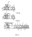
- Casting-mould parts in the form of moulds 5 consisting of mould sand or the like may be produced in a manner known per se by, as shown in Figure 2a, introducing a suitable quantity of mould sand into the mould chamber 1 through a hopper 4, after which squeeze plates 2,3 are moved towards each other, causing the mould sand in the mould chamber 1 to be compacted so as to form the desired mould 5.
- the parts 1-4 are parts in the mould-making station A shown in Figure 1.
- the squeeze plate 3 is pivoted away from the mould chamber 1 and the latter's bottom 6 as shown in Figure 2c.
- the squeeze plate 2 is advanced further with the mould 5 along the bottom 6, the latter continuing as the precision conveyor 6, so that the squeeze plate 2 moves the mould 5 forward into abutment with the previously formed mould 5 in the string of moulds 5 consisting of moulds 5 abutting against each other and now also comprising the most recently formed mould 5.
- the squeeze plate 2 and the precision conveyor 6 move the string of moulds F one step further forward.
- the squeeze plate 2 is withdrawn to its initial position, and the squeeze plate 3 is pivoted downwardly to its initial position, after which the process can be repeated.
- the string of moulds F will be pushed forward step by step to the pouring region 7 (at the pouring station B in Figure 1), in which casting material is poured into the casting cavities 8 formed between the moulds 5 so as to produce the desired castings 9.
- the precision conveyor 6 advances the moulds 5 with the castings 9 step by step in the form of an undivided string of moulds F, and during this movement, the cooling of the castings 9 is initiated in the first cooling section C shown in Figure 1. Firstly, this cooling occurs by heat energy being transferred to the material in the moulds 5, after which the heat is conducted through this material and dissipated from its surfaces. During this conduction of heat after the immediate heating, the mould sand acts as heat insulation relative to the castings 9.
- the string of moulds F continues on the precision conveyor 6 until it is transferred to the next conveying run.
- the succeeding conveying run may constitute an extension of the precision conveyor 6 and may be constructed and driven in such a manner that the moulds 5 will not be displaced relative to the string of moulds F, e.g. in the manner disclosed in DK-B-138,840, disclosing a conveyor belt being stabilized by rod-shaped means in engagement about the edges of the conveyor belt and accompanying the latter on a part of the conveying distance, thus preventing the moulds being opened by displacements relative to or in the belt.
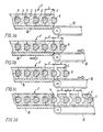
- the moulds 5 with the castings 9 are transferred from the first cooling section C to the second cooling section D, the latter being a conveyor, shown in Figure 3 in the form of a conveyor belt 10, that for each mould 5 being transferred is advanced through a greater distance S+s than the length S of the mould 5 previously having been transferred and entered into the string of moulds F, so that the latter is divided up with interspaces s between the moulds 5 along the latters' parting surfaces in the manner shown in Figures 1 and 3.
- the transfer as such may take place with uniform synchronized speed as between the string of moulds F and the conveyor belt 10, after which the string of moulds F stops while the conveyor belt 10 continues to advance e.g. 5-25 mm and then stops. With this cause of events, the continuous string of moulds F will be separated into individual moulds 5 with interspaces s adjusted to a desired magnitude, e.g. an interspace s of 5-25 mm.
- This interspace s can contribute to augmenting the cooling effect by increasing the surface area of the moulds 5 and by creating direct access to the castings.
- the cooling effect may be adjusted by varying the size of the interspace s, and it may possibly be adjusted a number of times with transfer to a new conveyor, during which the distance s is further increased by an increment sx to a greater distance s+sx.
- Figure 4 shows the extraction of the castings 9, these being extracted mechanically at an extraction station 11 (in Figure 1 being designated E), in which a gripping device engages the castings 9 through the interspaces s,sx between the moulds 5.
- E extraction station 11
- a gripping device engages the castings 9 through the interspaces s,sx between the moulds 5.
- the extraction station 11 may comprise a machine or a robot situated in a suitable extraction location.
- the extraction station may comprise detectors for detecting the openings s,sx between the moulds 5 and/or the castings 9 by mechanical sensing, photocells, ultrasound, inductive sensors or the like.
- the extraction of the castings 9 from the moulds 5 may be carried out by the mould 5 embracing the casting 9 and being forwardmost in the direction of movement of the moulds being overturned in the forward direction by advancing the gripping device 12 in the extraction station 11 after having gripped the casting, after which the latter is moved away from the conveyor belt 10. It is also possible to carry out the extraction by lifting the castings 9 up through the moulds 5, thus breaking open the upper part of the moulds 5. What these methods of extraction have in common is that they are simple to carry out and produce a small quantity of dust, because the moulds 5 are not subjected to a crushing operation during the introduction of gripping devices in the mould itself, such as is otherwise normal in extraction stations.
- This type of extraction makes it possible to transfer the mould 5 being overturned from the conveyor belt directly to a collecting space without any previous crushing or breaking up taking place, thus avoiding the creation of dust.
- the moulds 5 have such a shape that the castings 5 may be supported by one of them, the moulds can be moved with a relatively large mutual distance, thus improving the cooling and making it possible, if desired, to overturn the mould as shown in Figure 5.
- the conveyor belt 10 is protected against the influence of heat from the casting 9, because the mould 5 acts as heat insulation.
- the mould 5 protects the conveyor belt 10 against hot falling parts from the castings 9 and hot particles coming loose in the region of the casting cavity in the mould 5, such as otherwise could especially constitute a problem during the extraction at the extraction station 11.
- the conveyor 10 may be constituted by a conveyor belt, but it may also be constructed differently, e.g. in the form of a "travelling grate".
- the conveyor belt 10 is provided with sideboards or side rails, preferably having corrugations, causing mould parts or pieces from the moulds 5 to remain on the conveyor belt 10 to be collected at the downstream end.
- the conveyor belt 10 may also be provided with spaced abutments 13 as indicated in Figure 5, so that the string of moulds F will push the conveyor belt forward through a given distance when a mould 5 is being pushed onto the conveyor belt 10, as the forwardmost mould 5 in the string F will be advanced together with the latter until it engages an abutment 13, after which the conveyor belt 10 will be moved forward by the string F, and then, when the latter stops, the conveyor belt 10 continues to advance until a new abutment 13 is brought into position in front of the string of moulds F.
- the speed of the string F may be greater than the speed of the conveyor belt 10, but differentiated over the complete cycle time T, the speed is greatest for the conveyor belt.
- spaced abutments 13 may possibly be constructed and arranged in such a manner that their position may be altered according to the desired interspace between the moulds 5 and the size of the latter.
- the conveyor belt 10 itself may be arranged to be run freely or to be driven, the latter alternative comprising a partial drive for overcoming part of the frictional resistance, e.g. with a constantly acting advancing force corresponding to 90% of what is needed to advance the conveyor belt 10, thus relieving the string of moulds F, as during this part of the movement it is not subjected to the friction of the precision conveyor 6 and is only required to provide 10% of the requisite force for advancing the conveyor belt 10.
Landscapes
- Engineering & Computer Science (AREA)
- Mechanical Engineering (AREA)
- Casting Devices For Molds (AREA)
- Belt Conveyors (AREA)
- Attitude Control For Articles On Conveyors (AREA)
- Agricultural Chemicals And Associated Chemicals (AREA)
- Heating, Cooling, Or Curing Plastics Or The Like In General (AREA)
- Moulds For Moulding Plastics Or The Like (AREA)
- Encapsulation Of And Coatings For Semiconductor Or Solid State Devices (AREA)
Abstract
Description
- A
- mould-making station
- B
- pouring station
- C
- first cooling section
- D
- second cooling section
- E
- extraction station
- F
- string of moulds
- S
- length
- S+s
- distance
- s
- interspace
- 1
- mould chamber
- 2
- squeeze plate
- 3
- squeeze plate
- 4
- hopper
- 5
- mould
- 6(,16)
- precision conveyor/bottom
- 7
- pouring region
- 8
- casting cavity
- 9
- casting(s)
- 10
- conveyor belt
- 11
- extraction station
- 12
- gripping device
- 13
- spaced abutments
- 14
- sideboard
- 16
- extension
Claims (11)
- A method of advancing moulds (5), after pouring to form castings (9) in mould cavities (8) leaving a foundry plant comprising a mould-making station (A,1-4) and a pouring station (B,7), said moulds (5) leaving said stations in the form of closely juxtaposed mould parts (5) with the castings (9) in casting cavities (8) at the mainly vertical parting surfaces between successive moulds (5), the latter constituting a mould string (F), in which each mould (5) occupies a given length (S) in the longitudinal direction of the mould string (F), comprising the steps of passing the mould string (F) over a precision conveyor (6,16) and transferring thereafter the mould string (F) to a second conveyor (10,16,D), characterized by advancing the second conveyor (10) in a controlled manner through a greater distance (S+s) than the length (S) of said individual mould (5) in the mould string (F) and stopping the second conveyor (10) when it has advanced said greater distance (S+s) each time said second conveyor (10) receives a mould (5) from the mould string (F), so as to produce an interspace (s) on the second conveyor (10) between consecutive moulds (5) along the mainly vertical parting surfaces.
- Method according to claim 1, characterized by the use of at least one further conveyor (10) downstream of said second conveyor (10), said further conveyor (10) during the transfer of a mould (5) from the preceeding conveyor (10) being advanced through a greater distance (S+s+sx) than the preceeding conveyor, so that the interspace (s+sx) between the successive moulds (5) is increased relative to the interspace (s) between the successive moulds on the preceding conveyor.
- Method according to claim 1 or 2, characterized in that the moulds (5) with the castings (9) are overturned at a moment in time later than the moment in time, in which an interspace (s,sx) has been created between the moulds (5).
- Method according to any one or any of the claims 1-3, characterized by the use of a second conveyor (10) in the form of a freely running conveyor, so that the force for advancing the conveyor is at least in part supplied by the mould string (F) during the forward movement of the latter.
- Method according to any one or any of the claims 1-4, characterized in that the second conveyor (10) is driven by means of an applied force, at least partially constituting the requisite advancing force.
- Method according to any one or any of the claims 1-5, characterized in that the castings (9) are gripped at surfaces having been laid bare and not being embraced by the mould (5), and then removed from the second conveyor (10).
- Apparatus for carrying out the method according to claims 1-6 and of the kind comprising a precision conveyor (6) for conveying mould parts (5), after having been poured to form castings (9) in the casting cavities (8) leaving a casting machine in the form of closely juxtaposed mould parts in the form of moulds (5) having casting cavities (8) at the mainly vertical parting surfaces between successive moulds (5) constituting a mould string (F), said apparatus comprising a second conveyor (10,16,D), to which the moulds (5) are transferred after having been discharged from said precision conveyor (6) or an extension of the latter (16), characterized in that the apparatus comprises means for adapting, controlling and/or driving the second mould receiving conveyor (10) in such a manner that each time it receives a mould (5) with a casting (9), it is advanced in a controlled manner through a distance (S+s, S+s+sx) greater than the longitudinal space (S, S+s) previously occupied by the mould (5) relative to a succeeding mould part (5) and then it is stopped so that on the second conveyor (10), a relative displacement (s, s+sx) between the individual moulds (5) in a direction away from each other takes place, said displacement mainly being produced at the mainly vertical parting surfaces.
- Apparatus according to claim 7, characterized in that said second conveyor (10) is constituted by a conveyor belt (10), especially an endless, flexible conveyor belt (10).
- Apparatus according to claim 8, characterized in that said second conveyor (10) is provided with at least one sideboard or side rail (14), especially in the form of a corrugated sideboard or side rail.
- Apparatus according to any one or any of the claims 7-9, characterized in that said second conveyor (10) is provided with spaced abutments (13), preferably being adjustable in position.
- Apparatus according to any one or any of the claims 7-10, characterized by an extraction station (11) having a gripping device (12) adapted to engage the castings (9) at the surfaces of the latter having been laid bare.
Applications Claiming Priority (3)
| Application Number | Priority Date | Filing Date | Title |
|---|---|---|---|
| DK034595A DK34595A (en) | 1995-03-30 | 1995-03-30 | Method of advancing molds and a plant for use in the practice of the method |
| DK34595 | 1995-03-30 | ||
| PCT/DK1996/000128 WO1996030140A1 (en) | 1995-03-30 | 1996-03-28 | Method and arrangement for conveying moulds with castings therein |
Publications (2)
| Publication Number | Publication Date |
|---|---|
| EP0817690A1 EP0817690A1 (en) | 1998-01-14 |
| EP0817690B1 true EP0817690B1 (en) | 2000-06-21 |
Family
ID=8092477
Family Applications (1)
| Application Number | Title | Priority Date | Filing Date |
|---|---|---|---|
| EP96909073A Expired - Lifetime EP0817690B1 (en) | 1995-03-30 | 1996-03-28 | Method and arrangement for conveying moulds with castings therein |
Country Status (10)
| Country | Link |
|---|---|
| US (1) | US6092585A (en) |
| EP (1) | EP0817690B1 (en) |
| JP (1) | JP2955369B2 (en) |
| CN (1) | CN1046443C (en) |
| AT (1) | ATE193985T1 (en) |
| AU (1) | AU5270396A (en) |
| DE (1) | DE69608956T2 (en) |
| DK (2) | DK34595A (en) |
| ES (1) | ES2150112T3 (en) |
| WO (1) | WO1996030140A1 (en) |
Cited By (1)
| Publication number | Priority date | Publication date | Assignee | Title |
|---|---|---|---|---|
| WO2013093131A1 (en) | 2011-12-22 | 2013-06-27 | Fundacion Tecnalia Research & Innovation | Moulding method, equipment for implementing said method and mould obtained by means of said method |
Families Citing this family (25)
| Publication number | Priority date | Publication date | Assignee | Title |
|---|---|---|---|---|
| DK55497A (en) * | 1997-05-14 | 1998-11-15 | Georg Fischer Disa As | Process for removing castings and plant for using the method |
| DE69905204T2 (en) * | 1999-08-16 | 2004-01-15 | Disa Ind As Herlev | INDEPENDENT CONTROL OF PRESSURE PLATE SPEED IN MANUFACTURING CASELESS SAND MOLDS |
| ES2183667B1 (en) * | 1999-11-19 | 2004-05-16 | Loramendi, S.A. | MOTOR MOLDING MACHINE, PERFECTED. |
| DE60011307T2 (en) * | 2000-09-27 | 2004-10-28 | Disa Industries A/S | METHOD AND DEVICE FOR THE STEP-BY-STEP PROCESSING OF CHILLERS IN A CASTING PLANT |
| AU2001221508A1 (en) * | 2000-12-15 | 2002-06-24 | Georg Fischer Disa A/S | Method and apparatus for extracting castings produced in a mould foundry plant |
| CN1276810C (en) * | 2001-06-01 | 2006-09-27 | 洛兰曼迪股份有限公司 | Vertical Shell Molding Machine |
| WO2003097275A1 (en) * | 2002-05-16 | 2003-11-27 | Disa Industries A/S | Transport system for a mould-string casting plant |
| US7140414B1 (en) | 2004-10-20 | 2006-11-28 | Hayes Lemmerz International, Inc. | Method of removing a gate remnant from a casting |
| US7806161B2 (en) * | 2006-12-08 | 2010-10-05 | Thyssenkrupp Waupaca Inc. | Molding and casting machine |
| PL2324941T5 (en) | 2008-08-07 | 2020-07-13 | Loramendi, S.Coop. | Device for actuating a closure plate in a vertical boxless mould casting machine and machine comprising said device |
| PL2774665T3 (en) * | 2009-02-05 | 2017-09-29 | List Technology Ag | Process for continuous treatment of polymer solutions |
| EP2357050B1 (en) * | 2010-02-10 | 2012-10-31 | Loramendi, S.COOP. | Mote molding machine |
| CN101927325B (en) * | 2010-04-22 | 2013-04-24 | 兰州理工大学 | Differential ingot pushing device for aluminum ingot continuous casting machine |
| CN101823145B (en) * | 2010-05-28 | 2011-11-16 | 马鞍山方圆动力科技有限公司 | Continuous model casting device of metal |
| US10173259B2 (en) | 2013-05-21 | 2019-01-08 | Loramendi, S. Coop. | Machine for producing sand moulds |
| WO2015018786A2 (en) * | 2013-08-06 | 2015-02-12 | Loramendi, S. Coop. | Method and system for producing sand moulds |
| CN103978198B (en) * | 2014-04-16 | 2016-01-20 | 宁国东方碾磨材料股份有限公司 | A kind of casting processing system |
| CN104028702B (en) * | 2014-06-05 | 2017-01-11 | 遵义久志通用机械有限公司 | High-efficiency casting device of two-sided stack boxes |
| CN107567360B (en) * | 2015-04-17 | 2019-07-16 | 迪萨工业有限公司 | Method and system for indexable mold |
| WO2018104842A2 (en) * | 2016-12-05 | 2018-06-14 | Disa Industries A/S | Sand moulding machine and method of producing sand mould parts |
| PT3842167T (en) | 2019-12-27 | 2022-11-23 | Castirgalu S A | Mold extraction device from mold string conveyor |
| JP7343876B2 (en) * | 2020-01-16 | 2023-09-13 | デンカ株式会社 | Sheet arrangement method and arrangement device |
| CN112296319A (en) * | 2020-11-02 | 2021-02-02 | 遂昌丰晟铸造有限公司 | High-precision casting cooling and casting device and its process |
| CN112719253A (en) * | 2021-01-15 | 2021-04-30 | 成都市新都区会书商贸有限公司 | Device for automatically completing demolding according to temperature |
| CN114082924A (en) * | 2021-11-24 | 2022-02-25 | 王林 | Automatic demoulding device for impurity separation in steel part forming |
Citations (1)
| Publication number | Priority date | Publication date | Assignee | Title |
|---|---|---|---|---|
| JPH0191959A (en) * | 1987-10-02 | 1989-04-11 | Toyota Motor Corp | Mold transfer device in vertical frameless molding line |
Family Cites Families (11)
| Publication number | Priority date | Publication date | Assignee | Title |
|---|---|---|---|---|
| US3840066A (en) * | 1972-12-29 | 1974-10-08 | R Taccone | Conveyor for a flaskless mold line |
| DK129397B (en) * | 1973-02-06 | 1974-10-07 | Dansk Ind Syndikat | Method of separating castings from molds of sand or similar material and plant for carrying out this method. |
| US3967667A (en) * | 1975-06-23 | 1976-07-06 | Robinson Joseph J | Golf club cover-holder construction |
| US4112999A (en) * | 1977-03-07 | 1978-09-12 | Roberts Corporation | Conveyor control system |
| US4261413A (en) * | 1978-09-07 | 1981-04-14 | The Osborn Manufacturing Corporation | Foundry molding system |
| WO1981002698A1 (en) * | 1980-03-24 | 1981-10-01 | E Buehler | Method and device for transport of a molding line comprised of frameless molds |
| WO1986007293A1 (en) * | 1985-06-05 | 1986-12-18 | Michael Achinger | Device for transporting horizontal separation, boxless sand casting molds for foundry |
| SU1212688A1 (en) * | 1984-05-17 | 1986-02-23 | Ордена Трудового Красного Знамени Научно-Исследовательский Институт Технологии Автомобильной Промышленности | Transport for moving moulds |
| JPS62171816A (en) * | 1986-01-23 | 1987-07-28 | Toshiba Corp | Cast piece conveying device |
| IT1232004B (en) * | 1989-03-02 | 1992-01-22 | Hitech Systems Srl | GROUPING AND SYNCHRONIZATION EQUIPMENT OF OBJECTS FOR PACKAGING MACHINES OR BOXING MACHINES |
| DK540189A (en) * | 1989-10-30 | 1991-01-23 | Dansk Ind Syndikat | PROCEDURE FOR INTERMITTING PROMOTION OF FORMULAS AND PLANT FOR USE IN EXERCISING THE PROCEDURE |
-
1995
- 1995-03-30 DK DK034595A patent/DK34595A/en not_active Application Discontinuation
-
1996
- 1996-03-28 CN CN96192969A patent/CN1046443C/en not_active Expired - Fee Related
- 1996-03-28 JP JP8528813A patent/JP2955369B2/en not_active Expired - Fee Related
- 1996-03-28 DE DE69608956T patent/DE69608956T2/en not_active Expired - Fee Related
- 1996-03-28 AU AU52703/96A patent/AU5270396A/en not_active Abandoned
- 1996-03-28 ES ES96909073T patent/ES2150112T3/en not_active Expired - Lifetime
- 1996-03-28 US US08/913,971 patent/US6092585A/en not_active Expired - Lifetime
- 1996-03-28 AT AT96909073T patent/ATE193985T1/en active
- 1996-03-28 EP EP96909073A patent/EP0817690B1/en not_active Expired - Lifetime
- 1996-03-28 DK DK96909073T patent/DK0817690T3/en active
- 1996-03-28 WO PCT/DK1996/000128 patent/WO1996030140A1/en not_active Ceased
Patent Citations (1)
| Publication number | Priority date | Publication date | Assignee | Title |
|---|---|---|---|---|
| JPH0191959A (en) * | 1987-10-02 | 1989-04-11 | Toyota Motor Corp | Mold transfer device in vertical frameless molding line |
Cited By (1)
| Publication number | Priority date | Publication date | Assignee | Title |
|---|---|---|---|---|
| WO2013093131A1 (en) | 2011-12-22 | 2013-06-27 | Fundacion Tecnalia Research & Innovation | Moulding method, equipment for implementing said method and mould obtained by means of said method |
Also Published As
| Publication number | Publication date |
|---|---|
| DK34595A (en) | 1996-10-01 |
| EP0817690A1 (en) | 1998-01-14 |
| JPH10510217A (en) | 1998-10-06 |
| DE69608956T2 (en) | 2000-10-19 |
| ES2150112T3 (en) | 2000-11-16 |
| DE69608956D1 (en) | 2000-07-27 |
| CN1179739A (en) | 1998-04-22 |
| ATE193985T1 (en) | 2000-07-15 |
| WO1996030140A1 (en) | 1996-10-03 |
| JP2955369B2 (en) | 1999-10-04 |
| AU5270396A (en) | 1996-10-16 |
| DK0817690T3 (en) | 2000-11-20 |
| CN1046443C (en) | 1999-11-17 |
| US6092585A (en) | 2000-07-25 |
Similar Documents
| Publication | Publication Date | Title |
|---|---|---|
| EP0817690B1 (en) | Method and arrangement for conveying moulds with castings therein | |
| US4118168A (en) | Guidance system for shallow articles discharged from a mold cavity | |
| KR890701309A (en) | Manufacturing method and apparatus for injection molded article having transfer layer formed | |
| US5011641A (en) | Preparation of shaped agglomerated particulate material | |
| US4549600A (en) | Plant for the production of castings in a stepwise advanced casting mould consisting of identical, flaskless mould parts | |
| CA1064670A (en) | Chill casting method and apparatus | |
| JPS58196156A (en) | Fully automatic die casting device | |
| US5079022A (en) | Mold displacement method for fixed surface type forming machine | |
| CN1040940A (en) | Formative method and device | |
| CA1042026A (en) | Method and apparatus for forming ingots into stable 4-unit fork truckable stacks | |
| US4054172A (en) | Device for the production of castings | |
| EP1402976B1 (en) | Vertical boxless mould casting machine | |
| US3659701A (en) | Cooling conveyor | |
| CA1131577A (en) | Continuous grate track length compensator | |
| EP3842167B1 (en) | Mold extraction device from mold string conveyor | |
| KR100360637B1 (en) | Retarded cooling system with granular insulation material | |
| SU1771436A3 (en) | Automated cashing production line | |
| SU1014649A1 (en) | Unit for knocking off casting moulds | |
| US4082135A (en) | Foundry apparatus for the separation of castings from casting moulds | |
| GB2285950A (en) | Moulding bricks in moulds with movable bottoms | |
| CH644538A5 (en) | Method for manufacturing a fragmented raw material and apparatus for implementing this method | |
| RU2077406C1 (en) | Machine for casting into pigs | |
| JPH09239523A (en) | Treatment of remaining material of casting and device therefor | |
| RU2179496C2 (en) | Casting plant | |
| JPS619944A (en) | Molded article distributor |
Legal Events
| Date | Code | Title | Description |
|---|---|---|---|
| PUAI | Public reference made under article 153(3) epc to a published international application that has entered the european phase |
Free format text: ORIGINAL CODE: 0009012 |
|
| 17P | Request for examination filed |
Effective date: 19971030 |
|
| AK | Designated contracting states |
Kind code of ref document: A1 Designated state(s): AT BE CH DE DK ES FI FR GB GR IE IT LI LU MC NL PT SE |
|
| 17Q | First examination report despatched |
Effective date: 19980619 |
|
| GRAG | Despatch of communication of intention to grant |
Free format text: ORIGINAL CODE: EPIDOS AGRA |
|
| GRAG | Despatch of communication of intention to grant |
Free format text: ORIGINAL CODE: EPIDOS AGRA |
|
| GRAH | Despatch of communication of intention to grant a patent |
Free format text: ORIGINAL CODE: EPIDOS IGRA |
|
| GRAH | Despatch of communication of intention to grant a patent |
Free format text: ORIGINAL CODE: EPIDOS IGRA |
|
| GRAA | (expected) grant |
Free format text: ORIGINAL CODE: 0009210 |
|
| AK | Designated contracting states |
Kind code of ref document: B1 Designated state(s): AT BE CH DE DK ES FI FR GB GR IE IT LI LU MC NL PT SE |
|
| PG25 | Lapsed in a contracting state [announced via postgrant information from national office to epo] |
Ref country code: NL Free format text: LAPSE BECAUSE OF FAILURE TO SUBMIT A TRANSLATION OF THE DESCRIPTION OR TO PAY THE FEE WITHIN THE PRESCRIBED TIME-LIMIT Effective date: 20000621 Ref country code: LI Free format text: LAPSE BECAUSE OF FAILURE TO SUBMIT A TRANSLATION OF THE DESCRIPTION OR TO PAY THE FEE WITHIN THE PRESCRIBED TIME-LIMIT Effective date: 20000621 Ref country code: CH Free format text: LAPSE BECAUSE OF FAILURE TO SUBMIT A TRANSLATION OF THE DESCRIPTION OR TO PAY THE FEE WITHIN THE PRESCRIBED TIME-LIMIT Effective date: 20000621 Ref country code: BE Free format text: LAPSE BECAUSE OF FAILURE TO SUBMIT A TRANSLATION OF THE DESCRIPTION OR TO PAY THE FEE WITHIN THE PRESCRIBED TIME-LIMIT Effective date: 20000621 Ref country code: AT Free format text: LAPSE BECAUSE OF FAILURE TO SUBMIT A TRANSLATION OF THE DESCRIPTION OR TO PAY THE FEE WITHIN THE PRESCRIBED TIME-LIMIT Effective date: 20000621 Ref country code: FI Free format text: LAPSE BECAUSE OF FAILURE TO SUBMIT A TRANSLATION OF THE DESCRIPTION OR TO PAY THE FEE WITHIN THE PRESCRIBED TIME-LIMIT Effective date: 20000621 |
|
| REF | Corresponds to: |
Ref document number: 193985 Country of ref document: AT Date of ref document: 20000715 Kind code of ref document: T |
|
| RIN1 | Information on inventor provided before grant (corrected) |
Inventor name: JESPERSEN, EMIL Inventor name: LARSEN, JENS, PETER |
|
| REG | Reference to a national code |
Ref country code: CH Ref legal event code: EP |
|
| ET | Fr: translation filed | ||
| REG | Reference to a national code |
Ref country code: IE Ref legal event code: FG4D |
|
| REF | Corresponds to: |
Ref document number: 69608956 Country of ref document: DE Date of ref document: 20000727 |
|
| ITF | It: translation for a ep patent filed | ||
| PG25 | Lapsed in a contracting state [announced via postgrant information from national office to epo] |
Ref country code: SE Free format text: LAPSE BECAUSE OF FAILURE TO SUBMIT A TRANSLATION OF THE DESCRIPTION OR TO PAY THE FEE WITHIN THE PRESCRIBED TIME-LIMIT Effective date: 20000921 Ref country code: PT Free format text: LAPSE BECAUSE OF FAILURE TO SUBMIT A TRANSLATION OF THE DESCRIPTION OR TO PAY THE FEE WITHIN THE PRESCRIBED TIME-LIMIT Effective date: 20000921 |
|
| PG25 | Lapsed in a contracting state [announced via postgrant information from national office to epo] |
Ref country code: GR Free format text: LAPSE BECAUSE OF FAILURE TO SUBMIT A TRANSLATION OF THE DESCRIPTION OR TO PAY THE FEE WITHIN THE PRESCRIBED TIME-LIMIT Effective date: 20000922 |
|
| REG | Reference to a national code |
Ref country code: ES Ref legal event code: FG2A Ref document number: 2150112 Country of ref document: ES Kind code of ref document: T3 |
|
| REG | Reference to a national code |
Ref country code: DK Ref legal event code: T3 |
|
| NLV1 | Nl: lapsed or annulled due to failure to fulfill the requirements of art. 29p and 29m of the patents act | ||
| REG | Reference to a national code |
Ref country code: CH Ref legal event code: PL |
|
| PG25 | Lapsed in a contracting state [announced via postgrant information from national office to epo] |
Ref country code: LU Free format text: LAPSE BECAUSE OF NON-PAYMENT OF DUE FEES Effective date: 20010328 Ref country code: IE Free format text: LAPSE BECAUSE OF NON-PAYMENT OF DUE FEES Effective date: 20010328 |
|
| PG25 | Lapsed in a contracting state [announced via postgrant information from national office to epo] |
Ref country code: MC Free format text: LAPSE BECAUSE OF NON-PAYMENT OF DUE FEES Effective date: 20010331 |
|
| PLBE | No opposition filed within time limit |
Free format text: ORIGINAL CODE: 0009261 |
|
| STAA | Information on the status of an ep patent application or granted ep patent |
Free format text: STATUS: NO OPPOSITION FILED WITHIN TIME LIMIT |
|
| 26N | No opposition filed | ||
| REG | Reference to a national code |
Ref country code: GB Ref legal event code: IF02 |
|
| REG | Reference to a national code |
Ref country code: IE Ref legal event code: MM4A |
|
| PGFP | Annual fee paid to national office [announced via postgrant information from national office to epo] |
Ref country code: FR Payment date: 20030305 Year of fee payment: 8 |
|
| PGFP | Annual fee paid to national office [announced via postgrant information from national office to epo] |
Ref country code: GB Payment date: 20030310 Year of fee payment: 8 |
|
| PGFP | Annual fee paid to national office [announced via postgrant information from national office to epo] |
Ref country code: DK Payment date: 20030331 Year of fee payment: 8 |
|
| PG25 | Lapsed in a contracting state [announced via postgrant information from national office to epo] |
Ref country code: GB Free format text: LAPSE BECAUSE OF NON-PAYMENT OF DUE FEES Effective date: 20040328 |
|
| PG25 | Lapsed in a contracting state [announced via postgrant information from national office to epo] |
Ref country code: DK Free format text: LAPSE BECAUSE OF NON-PAYMENT OF DUE FEES Effective date: 20040331 |
|
| GBPC | Gb: european patent ceased through non-payment of renewal fee |
Effective date: 20040328 |
|
| PG25 | Lapsed in a contracting state [announced via postgrant information from national office to epo] |
Ref country code: FR Free format text: LAPSE BECAUSE OF NON-PAYMENT OF DUE FEES Effective date: 20041130 |
|
| REG | Reference to a national code |
Ref country code: FR Ref legal event code: ST |
|
| PG25 | Lapsed in a contracting state [announced via postgrant information from national office to epo] |
Ref country code: IT Free format text: LAPSE BECAUSE OF NON-PAYMENT OF DUE FEES Effective date: 20050328 |
|
| PGFP | Annual fee paid to national office [announced via postgrant information from national office to epo] |
Ref country code: ES Payment date: 20060330 Year of fee payment: 11 |
|
| PGFP | Annual fee paid to national office [announced via postgrant information from national office to epo] |
Ref country code: DE Payment date: 20060331 Year of fee payment: 11 |
|
| PG25 | Lapsed in a contracting state [announced via postgrant information from national office to epo] |
Ref country code: DE Free format text: LAPSE BECAUSE OF NON-PAYMENT OF DUE FEES Effective date: 20071002 |
|
| REG | Reference to a national code |
Ref country code: ES Ref legal event code: FD2A Effective date: 20070329 |
|
| PG25 | Lapsed in a contracting state [announced via postgrant information from national office to epo] |
Ref country code: ES Free format text: LAPSE BECAUSE OF NON-PAYMENT OF DUE FEES Effective date: 20070329 |