EP0817112A2 - Ink-jet printing method and apparatus therefor - Google Patents
Ink-jet printing method and apparatus therefor Download PDFInfo
- Publication number
- EP0817112A2 EP0817112A2 EP97304270A EP97304270A EP0817112A2 EP 0817112 A2 EP0817112 A2 EP 0817112A2 EP 97304270 A EP97304270 A EP 97304270A EP 97304270 A EP97304270 A EP 97304270A EP 0817112 A2 EP0817112 A2 EP 0817112A2
- Authority
- EP
- European Patent Office
- Prior art keywords
- ink
- printing
- data
- printhead
- Prior art date
- Legal status (The legal status is an assumption and is not a legal conclusion. Google has not performed a legal analysis and makes no representation as to the accuracy of the status listed.)
- Granted
Links
Images


Classifications
-
- B—PERFORMING OPERATIONS; TRANSPORTING
- B41—PRINTING; LINING MACHINES; TYPEWRITERS; STAMPS
- B41J—TYPEWRITERS; SELECTIVE PRINTING MECHANISMS, i.e. MECHANISMS PRINTING OTHERWISE THAN FROM A FORME; CORRECTION OF TYPOGRAPHICAL ERRORS
- B41J2/00—Typewriters or selective printing mechanisms characterised by the printing or marking process for which they are designed
- B41J2/005—Typewriters or selective printing mechanisms characterised by the printing or marking process for which they are designed characterised by bringing liquid or particles selectively into contact with a printing material
- B41J2/01—Ink jet
- B41J2/21—Ink jet for multi-colour printing
- B41J2/2121—Ink jet for multi-colour printing characterised by dot size, e.g. combinations of printed dots of different diameter
- B41J2/2128—Ink jet for multi-colour printing characterised by dot size, e.g. combinations of printed dots of different diameter by means of energy modulation
-
- G—PHYSICS
- G06—COMPUTING; CALCULATING OR COUNTING
- G06K—GRAPHICAL DATA READING; PRESENTATION OF DATA; RECORD CARRIERS; HANDLING RECORD CARRIERS
- G06K15/00—Arrangements for producing a permanent visual presentation of the output data, e.g. computer output printers
- G06K15/02—Arrangements for producing a permanent visual presentation of the output data, e.g. computer output printers using printers
- G06K15/10—Arrangements for producing a permanent visual presentation of the output data, e.g. computer output printers using printers by matrix printers
- G06K15/102—Arrangements for producing a permanent visual presentation of the output data, e.g. computer output printers using printers by matrix printers using ink jet print heads
Definitions
- the present invention relates to an ink-jet printing method and apparatus therefor for printing by discharging ink from a printhead onto a print medium.
- a printing apparatus such as a printer, copy machine, facsimile or the like is constructed to print dots on a print medium e.g. a sheet of paper or a thin plastic plate or the like, with the use of each of printing elements (nozzles, heating elements, wire and the like), and to form an image consisting of these dots.
- the printing apparatus of this type can be classified by the printing system, such as the ink-jet printing system, wire-dot printing system, thermal printing system, laser beam printing system and the like.
- the ink-jet printing system (ink-jet printer) is structured to discharge ink drops (printing liquid) from orifices of a printhead to a print medium, thereby printing an image.
- the ink-jet printer performs printing by discharging ink from a printhead, it is possible to realize printing without contacting the print medium, making it possible to stabilize image quality.
- pictorial image data can be readily processed utilizing an application program on a host computer.
- printers serving as output units of such computers are required to have the capability to output pictorial images as well.
- outputting operation of a pictorial image was performed by a printing apparatus adopting the silver salt printing system which is an advanced printing apparatus for inputting a digital image, or sublimation printing system which is an expensive printing apparatus dedicated to output photographs using sublimation dye.
- Such printing apparatus used conventionally to print photographic images or the like was extremely expensive.
- One of the reasons is in that the silver salt printing system requires extremely complicated processes and that the apparatus was so large that it cannot be used as a desk-top device.
- the apparatus using sublimation dye as the size of a print medium becomes large, the cost for the main unit and running cost become extremely high. Therefore, individuals could not use these apparatuses with ease.
- the largest disadvantage of these apparatuses is that these apparatuses are designed to use a particular print medium. In other words, the type of a print medium a user can use is limited. Since a regular sheet of paper is normally used to print documents or graphics or the like in a personal home or general business environment, color photographic images are difficult to print since they require a special sheet to print pictorially.
- the ink-jet printer is known as a printing apparatus that minimizes such limitation related to a print medium.
- the ink-jet printer has lately provided a type that can print a color photographic image with great improvement in its image quality, by improving image processes, colorant and print medium or the like.
- a printing method realized by changing the amount of ink discharged from a printhead is available. According to this method, the amount of ink discharge is uniformly and relatively decreased in a high-resolution mode. Moreover, a printhead which can arbitrarily modulate the amount of ink discharged from each nozzle has been suggested.
- a diameter of a dot in the image is reduced to a minute size in order to decrease granularity (sense of roughness) in a dark portion of the image.
- granularity sense of roughness
- Another method of printing is to utilize mixture of large dots having long diameter and small dots having short diameter. According to this method, poor print efficiency in image forming can be improved.
- This method is feasible in a case where a single nozzle is provided for each color; however, in a case where a plurality of nozzles are provided for each color, it becomes difficult to realize, and the larger the number of nozzles, the more difficult to realize.
- each nozzle discharges ink drops with frequency of several KHz or more. If the number of nozzles is small, the ink discharge operation can be controlled directly by a CPU. However, as the number of nozzles increases, the ink discharge needs to be controlled in terms of processing speed by hardware along with hardware circuits such as a gate array or the like. Note that in order to modulate the discharging amount of ink by making use of large dots and small dots, a driving pulse for discharge is modulated, or plural driving elements for large dots and small dots are provided for each nozzle to be driven alternatively.
- printing operation can be realized by plural scanning operation, combining scanning for printing large dots and scanning for printing small dots.
- this method it is possible to generate an image having the mixture of large dots and small dots with a simple construction.
- this method always requires plural times of scanning operation (hereinafter referred to as multiple pass printing). For instance, even if small dots are printed for almost all addresses in single scanning and there is only one large dot in the single scanning line, scanning operation must be performed twice to print that one large dot.
- the number of times of multiple pass printing increases, the printing requires longer time in reality. Therefore, the number of times of multiple pass printing must be minimized.
- print control in the printing apparatus is executed by switching between the printing operation with large dots and the printing operation with small dots for each scanning operation.
- a problem occurs in that, in a case where small dots are printed in all the printable grid points, meaningless scanning must be executed for printing a large dot even if there is no large dot to be printed.
- 100% of the printing processing is executed by one of two scanning (small dots)
- the advantage of divided printing that is, the characteristic of multiple pass printing which enables to solve the problems such as an uneven amount of ink discharged from a nozzle or an unequal amount of paper conveyance, cannot be attained.
- the ratio of printing amount is not equal for each scanning operation, problems arise in that an error rate is not decreased in scanning operation having a high printing ratio, or that electricity consumption is not reduced since the scanning operation having a high printing ratio consumes high instantaneous electricity.
- the present invention has been made in consideration of the above situation, and has as its object to provide an ink-jet printing method and apparatus therefor which can print an image in different tones in accordance with print data.
- An aspect of the present invention is to modulate the amount of ink discharge in order to form dots having different diameters, and to supply print data at the timing synchronous to the ink discharge timing of forming a desired dot's diameter, thereby enabling to modulate dot's diameter in one scanning operation with a simple construction of the apparatus.
- another aspect of the present invention is to provide an ink-jet printing method and apparatus therefor which can improve image quality by additionally printing a dot in a printed image to obviate a space between printed dots in a case of printing print data having high density.
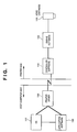
- Fig. 1 is a block diagram showing the arrangement of a print system as the embodiment of the present invention.
- the print system is constructed such that a host computer performs processing of various data with an application software 102 which generally works on an OS (operating system) 101.
- OS operating system
- description will be provided on data flow in a case where image data generated by the application software 102 for handling pictorial images is outputted to a printer via a printer driver 103.
- Image data processed by the application software 102 is, if the image data is a pictorial image, sent to the printer driver 103 as multi-valued R, G and B data.
- the printer driver 103 performs color processing on the multi-valued R, G and B data received from the application software 102, then further performs half-tone processing, and converts the data to C, M, Y and K data normally having binary value.
- the converted image data is outputted via a printer interface in the host computer, or via an interface to a memory unit such as files or the like. In Fig. 1, image data is outputted to the printer via an interface to the printer.
- the image data is received, being controlled by controller software 104 and the received image data is sent to engine software 105 after checking conformability to a print mode and an ink-jet cartridge (head cartridge 106).
- the engine software 105 receives the image data containing a print mode and data structure designated by the controller software 104, generates an ink-discharging pulse in accordance with the image data and outputs the pulse to the head cartridge 106.
- the head cartridge 106 discharges respective color ink and prints a color image, corresponding to the image data, on a print medium.
- the head cartridge 106 incorporates ink tanks containing respective colors of ink integrated with a printhead.
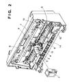
- Fig. 2 is a drawing which shows a mechanical structure of a cartridge-exchangeable type ink-jet printing apparatus, which is the preferable embodiment of the present invention.
- Fig. 2 shows the condition where a front cover of the ink-jet printing apparatus is removed to reveal the internal structure of the apparatus.
- Reference numeral 1 denotes an exchangeable-type head cartridge (corresponding to 106 in Fig. 1) comprising ink-tank units for containing ink and printheads.
- Reference numeral 2 denotes a carriage unit for performing printing by reciprocal movement while loading the head cartridge 1.
- Reference numeral 3 denotes a holder which stabilizes the head cartridge 1 and moves in correspondence with a cartridge stabilizing lever 4. More specifically, the cartridge stabilizing lever 4 is activated after the head cartridge 1 is loaded on the carriage unit 2, thereby tightly securing the head cartridge 1 to the carriage unit 2. On account of this, position of the head cartridge 1 is determined, and electrical contact between the head cartridge 1 and carriage unit 2 is achieved.
- Reference numeral 5 denotes a flexible cable for transmitting electrical signals to the carriage unit 2.
- Reference numeral 6 denotes a carriage motor whose rotation enables to reciprocally move the carriage unit 2 in the main-scanning direction.
- Reference numeral 7 denotes a carriage belt moved by the carriage motor 6 to horizontally move the carriage unit 2.
- Reference numeral 8 denotes a guide shaft for slidably supporting the carriage unit 2.
- Reference numeral 9 denotes a home position sensor comprising a photocoupler for determining a home position of the carriage unit 2.
- Reference numeral 10 denotes a shading plate used to detect the home position. When the carriage unit 2 reaches the home position, the shading plate shades the photocoupler provided in the carriage unit 2, whereby detecting that the carriage unit 2 has reached the home position.
- Reference numeral 12 denotes a home position unit including a printhead recovery mechanism for the printhead of the head cartridge 1.
- Reference numeral 13 denotes a paper discharge roller which holds a print medium with a spur unit (not shown) and discharges the print medium out of the printing apparatus.
- Reference numeral 14 denotes an LF unit which conveys a print medium for a predetermined amount in the sub-scanning direction.
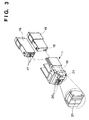
- Fig. 3 shows details of the head cartridge 1 used in the present embodiment.
- Reference numeral 15 denotes an exchangeable ink tank for black (Bk); and 16, an exchangeable ink tank containing ink for C, M and Y color ink.
- Reference numeral 17 denotes connection openings (color toner supply orifice) of the ink tank 16 which supply color toner (ink) coupled with the head cartridge 1; and 18, a connection opening of the ink tank 15.
- the ink supply orifices 17 and 18 are connected to supply tubes 20 to supply each color ink to a printhead unit 21 having Y, M, C and Bk printheads.
- Reference numeral 19 is a contact portion of electrical signals, and is connected to the flexible cable 5 (Fig. 2) to transmit various signals to the head cartridge 1.
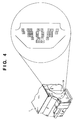
- Fig. 4 shows details of the contact portion 19 of the head cartridge 1.
- a plurality of electrode pads are mounted, through which signals related to ink discharge or ID signals for recognizing head cartridge 1 or the like are exchanged with the main unit of the ink-jet printing apparatus.
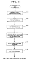
- Fig. 5 is a flowchart showing image processing performed by an image processing module in the printer driver 103.
- step S101 luminance-density conversion is performed to convert R, G and B luminance signals, that is, 24-bit input signals each of R, G and B having 8 bits, into C, M and Y signals, that is, 24-bit signals each of C, M and Y having 8 bits, or 32-bit signals each of C, M, Y and K having 8 bits.
- step S102 masking processing is performed, correcting unnecessary color component in the C, M and Y color ink.
- step S103 UCR/BGR processing is performed to remove under colors and extract black component.
- step S104 primary color (R, G and B) and secondary color (C, M and Y or C, M, Y and K) are limited to different discharging amount with respect to each pixel.
- primary color is limited to 300%; and secondary color, 400%.
- step S105 gamma correction is performed such that the characteristic of an output is linear. Up to this point, processing is performed on multi-value data each color having 8 bits.
- step S106 the 8-bit signals are subjected to half-tone processing and each of the C, M, Y and K color data is converted to signals having 1 bit or 2 bits.
- Half-tone processing in step S106 can be performed by error-diffusion method, dither method or the like.
- Fig. 6 shows the arrangement of the circuit and the flow of signals in the head cartridge 1 of the printing apparatus according to the present embodiment. Particularly noted herein is that one nozzle has two heaters for discharging ink and that each of the heaters generates different amount of heat. By switching over the heater to be driven, the size of discharging ink drops (i.e. dot size to be printed) is changed. This printing method will be described later.
- reference numeral 601 denotes a heater board of the head cartridge 1.
- Image data 621 subjected to printing is serially transmitted from the main unit of the printing apparatus to the heater board 601 in synchronization with a clock signal 622.
- the serial image data 621 is maintained by a shift register 602 in synchronization with the shift clock signal 622.
- a latch signal 623 is outputted by the main unit of the printing apparatus, whereupon the data maintained in the shift register 602 is latched by a latch unit 603 in synchronization with the latch signal 623.
- the image data stored in the latch unit 603 is divided into specified groups by various methods so that dots are dispersedly distributed to each of the groups.
- an output of the latch unit 603 is selected and outputted to each heater driver.
- Reference numeral 605 denotes an odd/even selector which selects to drive either the nozzles having odd numbers in the printheads or the nozzles having even numbers.
- two heaters A and B respectively for a large dot and a small dot are provided for one nozzle.
- plurality of heat resistance units may be provided for one nozzle.
- the number of the heat resistance units to be driven at substantially the same time is altered to change the amount of heat energy to be generated, thereby modulating the amount of ink discharged from each nozzle.
- the shift register 602 and latch unit 603 have the same number of bits as the number of the nozzles. Printing operation corresponding to one array of head nozzles is performed in two cycles; first, data corresponding to large dots and small dots to be printed in the first printing cycle is stored in the shift register 602 and latch unit 603, and then data corresponding to large dots and small dots to be printed in the second printing cycle is stored in the shift register 602 and latch unit 603.
- the shift register 602 and latch unit 603 may respectively store the number of bits, twice as many as the number of nozzles (when one pixel consists of two bits).
- a heater 607 is driven by a heat enabling signal (HEA) 627 sent via a driver A606
- a large amount of ink is discharged by the nozzle No. 1, whereby forming a large dot.
- a heater 609 is driven by a heat enabling signal (HEB) 626 sent via a driver B608
- a small amount of ink is discharged by the nozzle No. 1, whereby forming a small dot.
- a heater 611 is driven by a driver A610, a large dot is formed; and when a heater 613 is driven by a driver B612, a small dot is formed.
- the corresponding nozzle's heater A or B is driven, whereby either a large dot or a small dot is outputted from the subject nozzles.
- the inputted heat enabling signal either HEB signal 626 or HEA signal 627, decides the dot's diameter of an ink drop to be discharged from the nozzle, and the block timing at which the print data is turned to high level (“1") decides which positions the large and small dots are to be discharged.
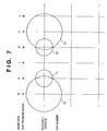
- a printhead has only one nozzle.
- the grid indicates a dot position printed by the printhead.
- the space of the grid in the main-scanning direction indicates 720 dpi (dot/inch).
- this nozzle is assumed to be the first nozzle of Block No. 1. Since the printhead has only one nozzle, the block-selection signal 624 for selecting the Block No. 1 and selection signal 625 for selecting nozzles having odd numbers, are ON (high level) each time.
- Image data "H” (Fig. 7) indicates a portion where there is data to be printed; and "L", a portion where there is no data to be printed.
- Signal "A” (Fig. 7) indicative of the heat enabling signal indicates to send a heat signal to the driver A for discharging ink (large dot); and signal "B", to send a heat signal to the driver B (small dot).
- the heat enabling (HEA) signal 627 is outputted when image data corresponding to the subject nozzle is at high level (H).
- the heat enabling (HEB) signal 626 is outputted when image data corresponding to the subject nozzle is at high level (H). Accordingly, small dots as indicated by reference numerals 90 to 92 are printed.
- FIG. 10 eight blocks (B1-B8) are provided for a printhead having sixteen nozzles.
- the nozzle indicated as nozzle No. 1 and the adjacent nozzle (nozzle No. 2) are defined as Block No. 1; and as the nozzle number increments, the block number is incremented by one.
- sixteen nozzles are divided into Block 1 (B1) to Block 8 (B8). In this state, a nozzle which satisfies the condition of four signals: the image data at high level (1), the heat enabling signal "ON,” the block-selection signal, and the odd/even selection signal, will be driven to discharge ink.
- Fig. 10 shows timings in a case where ink is discharged from all nozzles (No. 1 - No. 16) in one scanning operation and dots are printed, while scanning the printhead leftwards.
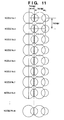
- Fig. 11 shows the arrangement of dots printed on a print medium by discharging ink from each nozzle at a timing in conformance to the addresses corresponding to a resolution of 720 dpi ⁇ 360 dpi. Note that Fig. 11 shows the state where each print data (2 bits) to be printed by all nozzles is "11" (to be described later in detail), and where large dots and small dots corresponding to respective two cycles (four dot columns) of printing are printed, while scanning the printhead leftwards.
- Fig. 12 is a block diagram showing the data flow transmitted from a control unit of the printing apparatus to the head cartridge 106. Components identical to those in the foregoing drawings are indicated by the same reference numerals and description thereof will be omitted.
- Reference numeral 200 denotes a CPU which controls operation of entire printing apparatus, and Fig. 12 shows only the flow of the signals in the portion related to the present embodiment.
- Reference numeral 201 denotes a RAM (random access memory), comprising a print buffer 210 which stores print data, a conversion data area 211 which stores conversion data for converting pixel data, a table 212, work area 213 and so on.
- Print data stored in the print buffer 210 consists of pixels each having two bits.
- a gate array (G.A) 202 reads out print data stored in the print buffer 210 by direct memory access (DMA). Normally, data is read out of the print buffer 210 in multiples of one word (16 bits).
- DMA direct memory access
- Reference numeral 204 denotes a data converter which converts pixel data utilizing conversion data. When multiple pass printing is performed, the data converter divides the data to be printed in each pass.
- Reference numeral 205 denotes a decoder which decodes (modulate) print data having two bits in accordance with modulation data stored in the table 212.
- Reference numeral 206 denotes a register of the G.A 202, and comprises a register 206a which stores data for forming large dots and a register 206b which stores data for forming small dots.
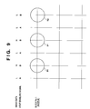
- Fig. 13 shows a part (only 32 nozzles) of a printhead comprising 256 nozzles.
- the head is constructed such that it is tilted by a predetermined angle ⁇ with respect to the scanning direction (horizontal direction in Fig. 13) of the head.
- ink is discharged by simultaneously driving two nozzles, e.g., in the first cycle, nozzle No. 1 and nozzle No. 17 for large dots, then nozzle No. 9 and nozzle No. 25 for small dots, then nozzle No. 2 and nozzle No. 18 for large dots, nozzle No. 10 and nozzle No. 26 for small dots and so on.
- ink is discharged simultaneously from two nozzles respectively: nozzles No. 1 and No. 17 for small dots, then nozzles No. 9 and No. 25 for large dots, nozzles No. 2 and No. 18 for small dots and so on, thereby printing an image corresponding to 32 pixels.
- nozzles No. 1 and No. 17 for large dots
- nozzles No. 9 and No. 25 for small dots
- nozzles No. 2 and No. 18 for large dots and so on.
- Fig. 13 shows the case where print data having two bits is all "11" (to be described later in detail).
- the data converter 204 and decoder 205 convert the data at the time of reading print data out of the print buffer 210, and store the converted data in the register 206 of the G.A 202.
- Several methods may be considered for a case of single pass printing and a case of multiple pass printing. Hereinafter, an embodiment of the single pass printing will be explained.
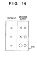
- Fig. 14 is an explanatory view showing that print data, in which each pixel read out of the print buffer 210 is expressed in two bits, is decoded by the decoder 205.
- the printing apparatus receives data expressed in the quaternary system (each pixel is expressed in two bits) which has been outputted by the printer driver 103 of the host computer, and writes the received data into the print buffer 210.
- the data each having two bits, written in the print buffer 210 is decoded by the two-bit decoder 205 in accordance with contents stored in the table 212, according to the relationship shown in Fig. 14, and is transferred by DMA to the register 206 of the G.A 202.
- the print data is transferred without being processed by the data converter 204.
- the print medium is conveyed at each scanning operation for a length corresponding to the 1/3 of the length of the nozzle array, whereby printing one band in three pass.
- a thinned out image (based on one-bit data) is first printed in the main-scanning direction, and then the print medium is advanced in the sub-scanning direction, further performing printing operation (based on one-bit data) in the main-scanning direction with respect to the portion thinned out in the previous main-direction scanning, to complete the image.
- two-bit data is outputted at each scan in the main-scanning direction as similar to the above-described case.
- decoding function is added to the conventional thin out function (herein, data conversion) to improve the capability of tone expression.
- print data expresses tone in two bits.
- data used for thin out (data conversion) is a combination of two bits of data, and is stored in the conversion data area 211 in the RAM 201.
- three groups of two-bit data (“aa” for the first pass, "bb” for the second pass and "cc” for the third pass) are allocated to the memory area 211 as shown in Fig. 17 such that each area has the equal number of data.
- the three groups of two-bit data are then shuffled.
- a random-number table having three groups of data randomly shifted is obtained as indicated by reference numerals 170, 171 and 172 in Fig. 17.
- the data generated in the above manner is stored in the conversion data area 211 shown in Fig. 12.
- the data converter 204 converts print data for each scanning operation in accordance with the above conversion data.
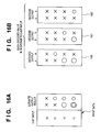
- Figs. 16A and 16B show an example thereof.
- Fig. 16A shows ultimate outputs of the two-bit data and Fig. 16B shows each of the decoded results for each scan in response to two-bit inputs.
- the data indicated by reference numeral 160 is an example where print data (two bits) is converted by data "aa” and further converted by the decoder 205 in accordance with the contents of the table 212; 161 (for the second pass), an example where print data is converted by data "bb” and further converted by the decoder 205 in accordance with the contents of the table 212; and 162 (for the third pass), an example where print data is converted by data "cc" and further converted by the decoder 205 in accordance with the contents of the table 212.
- Fig. 16A shows a printed example of each pixel of the print data printed in three scanning (three pass).
- print data "00” indicates to print nothing (XX denotes no dot); print data "01” indicates the lowest density where one small dot is printed within three-pass printing; print data "10” indicates that one large dot and one small dot are printed respectively; and print data "11” indicates that two large dots are overlappingly printed and one small dot is further printed.
- Figs. 16A and 16B are merely an example and the present invention is not limited to this.
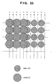
- a large dot is printed in addition to a small dot, printing a pair of a small dot and a large dot in separate positions as explained in Fig. 16A.
- a gap between the printed small dots is filled in by printing a large dot, enabling to obtain a print without any spaces between adjacent small dots.
- Fig. 19 shows a printed example where large dots are printed in a position indicated by reference numeral 190 and no small dot is printed in the adjacent position 191. In this case, a space is generated in the right side of the large dots.
- the above-described problem arises when two-bit input data changes from "01" (one small dot) to "10" (only one large dot).
- tone is to be expressed with sub pixels (a large dot and a small dot)
- a combination of a large dot and a small dot is printed for the data "10" as shown in Fig. 16A, thereby preventing from forming a gap in the printed image due to lack of one small dot.
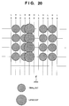
- Fig. 20 also shows a disadvantage occurred when only one large dot is printed for two-bit data "10.”
- a large dot is printed for the print data "10" in-between the small dots corresponding to the print data "01,” and a gap 2000 is generated in a section where image density changes.
- Fig. 21 shows the case where the above disadvantage is solved by printing a large dot and a small dot for the print data "10.”
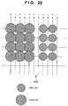
- Fig. 22 shows a printed example of a boundary between a dark portion printed in high density (data "10") and a light portion printed in low density (data "01"). Because of the same process as that of the Fig. 20, a gap 2200 is generated in the image portion where density changes ("10" ⁇ "01").
- Fig. 23 shows a printed example where such disadvantage in Fig. 22 is removed in the similar manner to that of Fig. 21.
- the present embodiment utilizes the table 212 having two-bit codes to also shuffle allocation of large and small dots, along with the groups of two-bit data. Therefore, even if the number of large dots or small dots are largely unbalanced, it is possible to uniformly allocate each size of the dots to each scanning by changing the codes of the table 212. Conventionally, when the above method is adopted, maximum of two dots are printed and three levels of tone are expressed based on two-bit data. However, by virtue of effective application of the above-described features, i.e., the head cartridge 106 capable of printing large dots and small dots, multiple pass printing, decoding in two-bit codes, random conversion data and so on, it is possible to perform printing, utilizing the combination of three large dots and three small dots at the maximum.
- combination patterns can be selected from the selectable sixteen patterns of tone.
- the number of pass of multiple pass printing may be increased, or two-bit codes are increased to three-bit codes or four-bit codes to largely increase the capability of tone expression, thereby increasing the dynamic range.
- the modulation is not necessarily the two levels of large and small, but plural levels of tone modulation is possible.
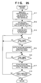
- Fig. 24 is a flowchart showing print processing performed by the ink-jet printing apparatus of the present embodiment. This process is executed while controlled by the CPU 200. The process starts when data is received from the host computer and print data corresponding to at least one scanning or one page is stored in the print buffer 210.
- step S1 the carriage motor 6 is driven to move the head cartridge 106; and in step S2, it is determined whether or not the printhead is at the print timing.
- step S3 the printhead is driven to perform printing corresponding to one array of nozzles of the printhead (shown in flowchart in Fig. 25).
- step S4 it is determined whether or not one line of print processing is completed. If one line of print processing is not completed, the processing returns to step S2; otherwise, the processing proceeds to step S5 where the carriage is returned, and a print sheet is advanced for a length corresponding to the printed width, then the processing proceeds to step S6.
- step S6 it is determined whether or not printing corresponding to one page is completed. If it is not completed, the processing returns to step S1, otherwise the processing proceeds to step S7 where the printed sheet of paper is discharged.
- step S11 print data corresponding to one array of nozzles is read out of the print buffer 210, and the data is subjected to go through the data converter 204, decoded by the decoder 205, and set in the registers 206a and 206b of the G.A 202 (step S12 performed by DMA).
- step S13 the data set in the registers 206a and 206b is transferred to the shift register 602 of the head cartridge 106. Since each nozzle forms one dot having one level of tone (consisting of two dots (upper and lower bit) at most) by respectively driving the heaters A and B, it is determined first in step S14 whether or not the heater A is at the driving timing.
- step S15 the block selection-signal 624 and odd/even selection signal 625 are outputted to specify nozzles to be driven simultaneously. Then, the HEA signal 627 for driving the heater A is outputted. As a result, if data (upper bit) corresponding to the selected nozzle is "1 (H)", the nozzles form large dots.
- step S16 determines whether or not the heater B is at driving timing. If the heater B is at driving timing, the processing proceeds to step S17 where the block-selection signal 624 and odd/even selection signal 625 are outputted to specify nozzles to be driven by the heater B, and the HEB signal 626 is outputted. As a result, if data (lower bit) corresponding to the selected nozzle is "1 (H)", the nozzles form small dots.
- step S18 it is determined whether or not printing is completed for all nozzles of the printhead. If the printing for all nozzles is completed, the processing returns to the beginning; otherwise, the processing proceeds to step S14 to determine timing of the heater A and timing of the heater B and perform printing by sequentially driving the remaining nozzles.
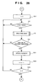
- Fig. 26 is a flowchart showing the process of three-pass printing according to the present embodiment. Processes that are identical to those in the above-described flowchart are indicated by the same step numerals and description thereof will be omitted.
- step S21 "3" is set at a counter n which counts the number of the pass.
- the data printed in correspondence with each scanning is generated by the data converter 204 and decoder 205.
- the present invention is particularly advantageous when applied to a printhead and a printing apparatus adopting the ink-jet printing method, particularly the type utilizing thermal energy.
- the system is effective because, by applying at least one driving signal, which corresponds to printing information and gives a rapid temperature rise exceeding film boiling, to each of electrothermal transducers arranged in correspondence with a sheet or liquid channels holding a liquid (ink), heat energy is generated by the electrothermal transducer to effect film boiling on the heat acting surface of the printhead, and consequently, a bubble can be formed in the liquid (ink) in one-to-one correspondence with the driving signal.
- the driving signal is applied as a pulse signal, the growth and shrinkage of the bubble can be attained instantly and adequately to achieve discharge of the liquid (ink) with the particularly high response characteristics.
- signals disclosed in U.S. Patent Nos. 4,463,359 and 4,345,262 are suitable. Note that further excellent printing can be performed by using the conditions described in U.S. Patent No. 4,313,124 of the invention which relates to the temperature rise rate of the heat acting surface.
- the arrangement using U.S. Patent Nos. 4,558,333 and 4,459,600 which disclose the arrangement having a heat acting portion arranged in a flexed region is also included in the present invention.
- the present invention can be effectively applied to an arrangement based on Japanese Patent Laid-Open No. 59-123670 which discloses the arrangement using a slot common to a plurality of electrothermal transducers as a discharge portion of the electrothermal transducers, or Japanese Patent Laid-Open No. 59-138461 which discloses the arrangement having an opening for absorbing a pressure wave of heat energy in correspondence with a discharge portion.
- a full line type printhead having a length corresponding to the width of the largest printing medium which can be printed by the printer, either the arrangement which satisfies the full-line length by combining a plurality of printheads as disclosed in the above specification or the arrangement as a single printhead obtained by forming printheads integrally can be used.
- an exchangeable chip-type printhead which enables electrical connection to the main unit or supplying of ink by being incorporated to the main unit of the printing apparatus, may also be utilized.
- recovery means for the printhead, preliminary auxiliary means, and the like provided as an arrangement of the printer of the present invention since the printing operation can be further stabilized.
- examples of such means include, for the printhead, capping means, cleaning means, pressurization or suction means, and preliminary heating means using electrothermal transducers, another heating element, or a combination thereof. It is also effective for stable printing to provide a preliminary discharge mode which performs discharge independently of printing.
- a printing mode of the printer not only a printing mode using only a primary color such as black or the like, but also at least one of a multicolor mode using a plurality of different colors or a full-color mode achieved by color mixing can be implemented in the printer either by using an integrated printhead or by combining a plurality of printheads.
- the ink is a liquid.
- the present invention may employ an ink which is solid at room temperature or less, or an ink which softens or liquefies at room temperature, or an ink which liquefies upon application of a printing signal, since it is a general practice to perform temperature control of the ink itself within a range from 30°C to 70°C in the ink-jet system, so that the ink viscosity can fall within a stable discharge range.
- an ink which is solid in a non-use state and liquefies upon heating may be used.
- an ink which liquefies upon application of heat energy according to a printing signal and is discharged in a liquid state, an ink which begins to solidify when it reaches a printing medium, or the like, is applicable to the present invention.
- an ink may be situated opposite to electrothermal transducers while being held in a liquid or solid state in recess portions of a porous sheet or through holes, as described in Japanese Patent Laid-Open No. 54-56847 or No. 60-71260.
- the above-mentioned film boiling system is most effective for the above-mentioned inks.
- the ink-jet printer of the present invention may be used in the form of a copying machine combined with a reader, and the like, or a facsimile apparatus having a transmission/reception function in addition to an image output terminal of an information processing equipment such as a computer.
- the present invention can be applied to a system constituted by a plurality of devices (e.g., host computer, interface, reader, printer) or to an apparatus comprising a single device (e.g., copy machine, facsimile).
- devices e.g., host computer, interface, reader, printer
- apparatus comprising a single device (e.g., copy machine, facsimile).
- the object of the present invention can be also achieved by providing a storage medium storing program codes for performing the aforesaid processes to a system or an apparatus, reading the program codes with a computer (e.g., CPU, MPU) of the system or apparatus from the storage medium, then executing the program.
- a computer e.g., CPU, MPU
- the program codes read from the storage medium realize the new functions according to the invention, and the storage medium storing the program codes constitutes the invention.
- the storage medium such as a floppy disk, hard disk, an optical disk, a magneto-optical disk, CD-ROM, CD-R, a magnetic tape, a non-volatile type memory card, and ROM can be used for providing the program codes.
- the present invention includes a case where an OS (Operating System) or the like working on the computer performs a part or entire processes in accordance with designations of the program codes and realizes functions according to the above embodiment.
- OS Operating System
- the present invention also includes a case where, after the program codes read from the storage medium are written in a function expansion card which is inserted into the computer or in a memory provided in a function expansion unit which is connected to the computer, a CPU or the like contained in the function expansion board or unit performs a part or entire process in accordance with designations of the program codes and realizes functions of the above embodiment.
- the above-described embodiment having simple construction can print plural sizes of dots on a print medium, even in the case of single-scan (pass) printing.
- the present invention has an effect which.has not conventionally been recognized, that is, in multiple pass printing, even in a case the number of dots and small dots printed in one pass is unbalanced (printing ratio of large dots to small dots is uneven), the printing ratio can be substantially equalized for each pass.
- mask data for multiple pass printing is additionally used, thereby enabling to select dots and allocate data to each pass simultaneously. Accordingly, it is possible to simplify control operation.
- the average printing ratio for each pass is balanced.
- error rate such as discharge failure or the like caused by printing in high printing ratio.
- the discharge amount is continuously changed for each nozzle, it is possible to reduce the average amount of ink discharge for each nozzle even if the printing ratio is high. As a result, it is possible to improve refill frequency, and reduce error rate.
Abstract
Description
Claims (18)
- An ink-jet printing apparatus for printing an image on a print medium by discharging ink from each of a plurality of printing elements of a printhead, characterised by comprising:ink-discharge-amount changing means (607, 609) for altering an amount of ink discharged from each of the printing elements of the printhead;modulate means (204, 205) for modulating print data such that an additional dot is provided as density of print data increases;timing control means (200) for determining ink discharge timing to discharge the amount of ink which is altered by said ink-discharge-amount changing means; andcontrol means (202) for outputting the print data modulated by said modulate means to the printhead in synchronization with the ink discharge timing determined by said timing control means.
- The ink-jet printing apparatus according to claim 1, characterised in that said timing control means determines ink discharge timing for at least printing a large dot by the printing elements, and ink discharge timing for printing a small dot by the printing elements.
- The ink-jet printing apparatus according to claim 1 or 2, characterised in that said ink-discharge-amount changing means comprises either a plurality of heat resistance units each of which having different heating capacities, or a plurality of heat resistance units each of which being provided on different locations for a single printing element, and said ink-discharge-amount changing means changes the discharge amount of ink by changing the number and/or the location of heat resistance units to be driven in substantially simultaneous timing.
- The ink-jet printing apparatus according to claim 1, characterised in that said control means controls at least a small dot or combination of a large dot and a small dot to express tone of the print data modulated by said modulate means.
- The ink-jet printing apparatus according to anyone of claims 1-4, characterised by further comprising:scan-data generating means for generating print data corresponding to each scanning by dividing the print data into data which corresponds to each scanning and modulating the divided data in accordance with modulation data; andmultiple pass control means for performing printing by a plurality of times of scanning on the basis of the print data generated by said scan-data generating means.
- The ink-jet printing apparatus according to claim 5, characterised in that the modulation data is random-number data provided in correspondence with each scanning.
- The ink-jet printing apparatus according to anyone of claims 1-6, wherein the printhead discharges ink utilizing thermal energy, and includes a thermal energy generator for generating thermal energy to be provided to ink.
- An ink-jet printing apparatus for performing printing by relatively moving a print medium and a printhead, characterised by comprising:ink-discharge-amount changing means (607, 609) for altering an amount of ink discharged from the printhead;modulate means (204, 205) for modulating multi-value image data to generate print data; andprint means (200, 202) for performing printing by changing the amount of ink discharged from the printhead by said ink-discharge-amount changing means, on the basis of the print data modulated by said modulate means,wherein each pixel of a multi-value image printed by said print means is formed by at least one small dot or combination of a large dot and a small dot.
- The ink-jet printing apparatus according to claim 8, characterised in that said print means performs printing by scanning the printhead for a plurality of times, and said modulate means generates print data by modulating the multi-value image data in correspondence with each scanning of the printhead.
- An ink-jet printing method of printing an image on a print medium by discharging ink from each of a plurality of printing elements of a printhead, characterised by comprising the steps of:modulating (S12) print data such that an additional dot is provided as density of print data increases;printing (S15, S16) an image on the print medium by outputting the print data modulated in said modulating step in synchronization with ink discharge timing of each printing element of the printhead which alters respective discharge amount of ink.
- The ink-jet printing method according to claim 10, characterised in that the ink discharge timing includes ink discharge timing for at least printing a large dot by the printing elements, and ink discharge timing for printing a small dot by the printing elements.
- The ink-jet printing method according to claim 10 or 11,
characterised in that the amount of ink discharged by the printhead is altered by a plurality of heat resistance units each of which having different heating capacities, or a plurality of heat resistance units each of which being provided on different locations for a single printing element, wherein the number and/or the location of the heat resistance units to be driven in substantially simultaneous timing is changed to alter the amount of ink discharge. - The ink-jet printing method according to claim 10, characterised in that printing is performed such that tone of the print data modulated in said modulating step is expressed by at least a small dot or combination of a large dot and a small dot.
- The ink-jet printing method according to anyone of claims 10-13, further comprising:a scan-data generating step of generating print data corresponding to each scanning by dividing the print data into data which corresponds to each scanning and modulating the divided data in accordance with modulation data; anda multiple pass control step (S21-S23) of performing printing by the printhead scanning for a plurality of times on the basis of the print data generated in said scan-data generating step.
- An ink-jet printing method for performing printing by relatively moving a print medium and a printhead, characterised by comprising the steps of:modulating (S12) multi-value image data to generate print data; andperforming (S15, S17) printing by changing the amount of ink discharged from the printhead in accordance with the print data modulated in said modulating step,wherein in said printing step, each pixel of a multi-value image printed is formed by at least one small dot or combination of a large dot and a small dot.
- The ink-jet printing method according to claim 15, characterised in that in said printing step, printing is performed by scanning the printhead for a plurality of times, and in said modulating step, print data is generated by modulating the multi-value image data in correspondence with each scanning of the printhead.
- An ink jet recording apparatus having at least one recording head with at least one recording element for discharging liquid to form dots on a recording medium or method or a control circuit for controlling operation of a recording head for an ink jet recording apparatus, wherein the diameter of a dot produced by a recording element is modulated in accordance with the data to be recorded.
- An ink jet recording apparatus having at least one recording head with at least one recording element for discharging liquid to form dots on a recording medium or method or a control circuit for controlling operation of a recording head for an ink jet recording apparatus, having the features recited in any one or any combination of the preceding claims.
Applications Claiming Priority (3)
| Application Number | Priority Date | Filing Date | Title |
|---|---|---|---|
| JP17038996 | 1996-06-28 | ||
| JP170389/96 | 1996-06-28 | ||
| JP17038996A JP3308815B2 (en) | 1996-06-28 | 1996-06-28 | Ink jet recording method and apparatus |
Publications (3)
| Publication Number | Publication Date |
|---|---|
| EP0817112A2 true EP0817112A2 (en) | 1998-01-07 |
| EP0817112A3 EP0817112A3 (en) | 1998-11-11 |
| EP0817112B1 EP0817112B1 (en) | 2004-08-25 |
Family
ID=15904030
Family Applications (1)
| Application Number | Title | Priority Date | Filing Date |
|---|---|---|---|
| EP97304270A Expired - Lifetime EP0817112B1 (en) | 1996-06-28 | 1997-06-18 | Ink-jet printing method and apparatus therefor |
Country Status (4)
| Country | Link |
|---|---|
| US (1) | US6305775B1 (en) |
| EP (1) | EP0817112B1 (en) |
| JP (1) | JP3308815B2 (en) |
| DE (1) | DE69730385T2 (en) |
Cited By (2)
| Publication number | Priority date | Publication date | Assignee | Title |
|---|---|---|---|---|
| EP0970815A1 (en) * | 1998-07-03 | 2000-01-12 | Seiko Epson Corporation | Printer and recording medium |
| CN100463803C (en) * | 2003-08-11 | 2009-02-25 | 佳能株式会社 | Inkjet recording method, and inkjet recording apparatus |
Families Citing this family (26)
| Publication number | Priority date | Publication date | Assignee | Title |
|---|---|---|---|---|
| US6786420B1 (en) | 1997-07-15 | 2004-09-07 | Silverbrook Research Pty. Ltd. | Data distribution mechanism in the form of ink dots on cards |
| JP3530717B2 (en) * | 1997-06-19 | 2004-05-24 | キヤノン株式会社 | Ink jet recording method and apparatus |
| US6618117B2 (en) | 1997-07-12 | 2003-09-09 | Silverbrook Research Pty Ltd | Image sensing apparatus including a microcontroller |
| US6803989B2 (en) * | 1997-07-15 | 2004-10-12 | Silverbrook Research Pty Ltd | Image printing apparatus including a microcontroller |
| AUPO850597A0 (en) | 1997-08-11 | 1997-09-04 | Silverbrook Research Pty Ltd | Image processing method and apparatus (art01a) |
| US6985207B2 (en) | 1997-07-15 | 2006-01-10 | Silverbrook Research Pty Ltd | Photographic prints having magnetically recordable media |
| US6879341B1 (en) | 1997-07-15 | 2005-04-12 | Silverbrook Research Pty Ltd | Digital camera system containing a VLIW vector processor |
| US6690419B1 (en) | 1997-07-15 | 2004-02-10 | Silverbrook Research Pty Ltd | Utilising eye detection methods for image processing in a digital image camera |
| US7110024B1 (en) | 1997-07-15 | 2006-09-19 | Silverbrook Research Pty Ltd | Digital camera system having motion deblurring means |
| AUPO802797A0 (en) | 1997-07-15 | 1997-08-07 | Silverbrook Research Pty Ltd | Image processing method and apparatus (ART54) |
| US6624848B1 (en) | 1997-07-15 | 2003-09-23 | Silverbrook Research Pty Ltd | Cascading image modification using multiple digital cameras incorporating image processing |
| US6948794B2 (en) | 1997-07-15 | 2005-09-27 | Silverbrook Reserach Pty Ltd | Printhead re-capping assembly for a print and demand digital camera system |
| AUPP702098A0 (en) | 1998-11-09 | 1998-12-03 | Silverbrook Research Pty Ltd | Image creation method and apparatus (ART73) |
| AUPQ056099A0 (en) | 1999-05-25 | 1999-06-17 | Silverbrook Research Pty Ltd | A method and apparatus (pprint01) |
| US20040252340A1 (en) * | 2001-10-03 | 2004-12-16 | Seiko Epson Corporation | Image processing system, image processing method, template producing system and template data structure |
| JP4059027B2 (en) * | 2001-10-03 | 2008-03-12 | セイコーエプソン株式会社 | Printer and printer print condition setting method |
| US6592203B1 (en) * | 2002-02-11 | 2003-07-15 | Lexmark International, Inc. | Subcovered printing mode for a printhead with multiple sized ejectors |
| EP1405724B1 (en) * | 2002-10-03 | 2008-09-03 | Canon Kabushiki Kaisha | Ink-jet printing method, ink-jet printing apparatus, and program |
| US7369267B2 (en) * | 2003-06-30 | 2008-05-06 | Lexmark International, Inc. | High resolution printing method |
| DE602004031888D1 (en) * | 2004-05-27 | 2011-04-28 | Silverbrook Res Pty Ltd | METHOD FOR AT LEAST PARTIALLY COMPENSATING ERRORS IN THE INK POSITIONING DUE TO INCORRECT TURNING SHIFT |
| US7290852B2 (en) * | 2004-05-27 | 2007-11-06 | Silverbrook Research Pty Ltd | Printhead module having a dropped row |
| US7140710B2 (en) * | 2004-06-28 | 2006-11-28 | Lexmark International, Inc. | Dot management for an imaging apparatus |
| JP5110780B2 (en) | 2005-07-28 | 2012-12-26 | キヤノン株式会社 | Image processing method and image processing apparatus |
| JP2008049563A (en) * | 2006-08-23 | 2008-03-06 | Canon Inc | Image processor, image recorder and recording data forming method |
| JP2011207230A (en) * | 2011-06-13 | 2011-10-20 | Canon Inc | Image processing apparatus and method for generating record data |
| WO2018190863A1 (en) | 2017-04-14 | 2018-10-18 | Hewlett-Packard Development Company, L.P. | Fluidic die with drop weight signals |
Citations (3)
| Publication number | Priority date | Publication date | Assignee | Title |
|---|---|---|---|---|
| FR2602462A1 (en) * | 1986-08-11 | 1988-02-12 | Millet Jean Claude | Ink-jet printing method and device |
| JPH07323552A (en) * | 1994-05-31 | 1995-12-12 | Canon Inc | Ink droplet discharge quantity controlling method, ink jet recorder and information processing system |
| JPH07323550A (en) * | 1994-05-31 | 1995-12-12 | Canon Inc | Controlling method for ink jet printer and the same printer |
Family Cites Families (13)
| Publication number | Priority date | Publication date | Assignee | Title |
|---|---|---|---|---|
| CA1127227A (en) | 1977-10-03 | 1982-07-06 | Ichiro Endo | Liquid jet recording process and apparatus therefor |
| JPS5936879B2 (en) | 1977-10-14 | 1984-09-06 | キヤノン株式会社 | Thermal transfer recording medium |
| US4330787A (en) | 1978-10-31 | 1982-05-18 | Canon Kabushiki Kaisha | Liquid jet recording device |
| US4345262A (en) | 1979-02-19 | 1982-08-17 | Canon Kabushiki Kaisha | Ink jet recording method |
| US4463359A (en) * | 1979-04-02 | 1984-07-31 | Canon Kabushiki Kaisha | Droplet generating method and apparatus thereof |
| US4313124A (en) | 1979-05-18 | 1982-01-26 | Canon Kabushiki Kaisha | Liquid jet recording process and liquid jet recording head |
| US4558333A (en) | 1981-07-09 | 1985-12-10 | Canon Kabushiki Kaisha | Liquid jet recording head |
| US4533928A (en) * | 1982-04-30 | 1985-08-06 | Canon Kabushiki Kaisha | Color image processing apparatus |
| JPS59123670A (en) | 1982-12-28 | 1984-07-17 | Canon Inc | Ink jet head |
| JPS59138461A (en) | 1983-01-28 | 1984-08-08 | Canon Inc | Liquid jet recording apparatus |
| JPS6071260A (en) | 1983-09-28 | 1985-04-23 | Erumu:Kk | Recorder |
| JPS6183046A (en) * | 1984-09-29 | 1986-04-26 | Minolta Camera Co Ltd | Ink jet recording apparatus capable of expression gradation |
| US6106102A (en) * | 1992-05-01 | 2000-08-22 | Hewlett-Packard Company | Odd number of passes, odd number of advances, and separated-diagonal-line masking, in liquid-ink printers |
-
1996
- 1996-06-28 JP JP17038996A patent/JP3308815B2/en not_active Expired - Fee Related
-
1997
- 1997-06-18 EP EP97304270A patent/EP0817112B1/en not_active Expired - Lifetime
- 1997-06-18 DE DE69730385T patent/DE69730385T2/en not_active Expired - Lifetime
- 1997-06-24 US US08/881,273 patent/US6305775B1/en not_active Expired - Lifetime
Patent Citations (3)
| Publication number | Priority date | Publication date | Assignee | Title |
|---|---|---|---|---|
| FR2602462A1 (en) * | 1986-08-11 | 1988-02-12 | Millet Jean Claude | Ink-jet printing method and device |
| JPH07323552A (en) * | 1994-05-31 | 1995-12-12 | Canon Inc | Ink droplet discharge quantity controlling method, ink jet recorder and information processing system |
| JPH07323550A (en) * | 1994-05-31 | 1995-12-12 | Canon Inc | Controlling method for ink jet printer and the same printer |
Non-Patent Citations (2)
| Title |
|---|
| Patent Abstracts of Japan, Vol. 96, No. 4, 30 April 1996; & JP,A,07-323550 (CANON INC), 12 December 1995, abstract, fig.. * |
| Patent Abstracts of Japan, Vol. 96, No. 4, 30 April 1996; & JP,A,07-323552 (CANON INC), 12 December 1995, abstract, fig.. * |
Cited By (3)
| Publication number | Priority date | Publication date | Assignee | Title |
|---|---|---|---|---|
| EP0970815A1 (en) * | 1998-07-03 | 2000-01-12 | Seiko Epson Corporation | Printer and recording medium |
| US6283571B1 (en) | 1998-07-03 | 2001-09-04 | Seiko Epson Corporation | Printer and recording medium |
| CN100463803C (en) * | 2003-08-11 | 2009-02-25 | 佳能株式会社 | Inkjet recording method, and inkjet recording apparatus |
Also Published As
| Publication number | Publication date |
|---|---|
| EP0817112A3 (en) | 1998-11-11 |
| US6305775B1 (en) | 2001-10-23 |
| DE69730385D1 (en) | 2004-09-30 |
| EP0817112B1 (en) | 2004-08-25 |
| DE69730385T2 (en) | 2005-08-18 |
| JP3308815B2 (en) | 2002-07-29 |
| JPH1016251A (en) | 1998-01-20 |
Similar Documents
| Publication | Publication Date | Title |
|---|---|---|
| EP0817112B1 (en) | Ink-jet printing method and apparatus therefor | |
| CA2208831C (en) | Recording method using large and small dots | |
| US7130083B1 (en) | Image recording apparatus, image recording method, method for controlling the image recording apparatus, storage medium storing a program capable of being read by a computer, and image processing method | |
| JP3423491B2 (en) | Image processing method, printing method, image processing device, printing device, and display device | |
| US5975678A (en) | Ink jet recording apparatus and method using plural types of ink | |
| US6942310B2 (en) | Ink-jet printing method and apparatus | |
| JPH1110842A (en) | Method and apparatus for ink jet recording | |
| JP3774505B2 (en) | Halftone recording apparatus, halftone recording method, ink tank, head cartridge, inkjet recording apparatus, and inkjet recording method | |
| US20020039118A1 (en) | Ink-jet printing apparatus and method, and computer readable memory | |
| US7436547B2 (en) | Image processing system, image processing device, image outputting device and method for same | |
| JP5317575B2 (en) | Data processing apparatus and data processing method | |
| US6467866B1 (en) | Print control method and apparatus, and printing apparatus using the same | |
| EP0855671B1 (en) | Image processing method and apparatus | |
| US7339698B1 (en) | Image processing method and apparatus | |
| JP2005224983A (en) | Image output system for outputting image according to information on number of dots formed in prescribed area | |
| JP2004322374A (en) | Image formation device and image formation method | |
| EP0932300B1 (en) | An ink jet apparatus and an ink jet printing method | |
| JP2004328160A (en) | Image forming apparatus and control method thereof | |
| US7167278B2 (en) | Image processing apparatus, image processing method, program for implementing the method | |
| JP2005007800A (en) | System for printing image based on information of the number of dots formed in specified region | |
| JP2001054962A (en) | Image recorder, image recording method, control method for image recorder, and computer readable storage medium | |
| JP2004328266A (en) | Quantization method | |
| JP2005205856A (en) | Device and method for image processing | |
| MXPA97004809A (en) | Registration method using large and small points | |
| JP2005210621A (en) | Image processing apparatus and image processing method |
Legal Events
| Date | Code | Title | Description |
|---|---|---|---|
| PUAI | Public reference made under article 153(3) epc to a published international application that has entered the european phase |
Free format text: ORIGINAL CODE: 0009012 |
|
| AK | Designated contracting states |
Kind code of ref document: A2 Designated state(s): DE FR GB IT |
|
| AX | Request for extension of the european patent |
Free format text: AL;LT;LV;RO;SI |
|
| PUAL | Search report despatched |
Free format text: ORIGINAL CODE: 0009013 |
|
| RHK1 | Main classification (correction) |
Ipc: G06K 15/00 |
|
| AK | Designated contracting states |
Kind code of ref document: A3 Designated state(s): AT BE CH DE DK ES FI FR GB GR IE IT LI LU MC NL PT SE |
|
| AX | Request for extension of the european patent |
Free format text: AL;LT;LV;RO;SI |
|
| 17P | Request for examination filed |
Effective date: 19990325 |
|
| AKX | Designation fees paid |
Free format text: DE FR GB IT |
|
| 17Q | First examination report despatched |
Effective date: 20011023 |
|
| GRAP | Despatch of communication of intention to grant a patent |
Free format text: ORIGINAL CODE: EPIDOSNIGR1 |
|
| GRAS | Grant fee paid |
Free format text: ORIGINAL CODE: EPIDOSNIGR3 |
|
| GRAA | (expected) grant |
Free format text: ORIGINAL CODE: 0009210 |
|
| AK | Designated contracting states |
Kind code of ref document: B1 Designated state(s): DE FR GB IT |
|
| REG | Reference to a national code |
Ref country code: GB Ref legal event code: FG4D |
|
| REF | Corresponds to: |
Ref document number: 69730385 Country of ref document: DE Date of ref document: 20040930 Kind code of ref document: P |
|
| ET | Fr: translation filed | ||
| PLBE | No opposition filed within time limit |
Free format text: ORIGINAL CODE: 0009261 |
|
| STAA | Information on the status of an ep patent application or granted ep patent |
Free format text: STATUS: NO OPPOSITION FILED WITHIN TIME LIMIT |
|
| 26N | No opposition filed |
Effective date: 20050526 |
|
| PGFP | Annual fee paid to national office [announced via postgrant information from national office to epo] |
Ref country code: IT Payment date: 20090620 Year of fee payment: 13 |
|
| REG | Reference to a national code |
Ref country code: FR Ref legal event code: ST Effective date: 20110228 |
|
| PG25 | Lapsed in a contracting state [announced via postgrant information from national office to epo] |
Ref country code: IT Free format text: LAPSE BECAUSE OF NON-PAYMENT OF DUE FEES Effective date: 20100618 |
|
| PG25 | Lapsed in a contracting state [announced via postgrant information from national office to epo] |
Ref country code: FR Free format text: LAPSE BECAUSE OF NON-PAYMENT OF DUE FEES Effective date: 20100630 |
|
| PGFP | Annual fee paid to national office [announced via postgrant information from national office to epo] |
Ref country code: GB Payment date: 20150626 Year of fee payment: 19 Ref country code: DE Payment date: 20150630 Year of fee payment: 19 |
|
| PGFP | Annual fee paid to national office [announced via postgrant information from national office to epo] |
Ref country code: FR Payment date: 20090624 Year of fee payment: 13 |
|
| REG | Reference to a national code |
Ref country code: DE Ref legal event code: R119 Ref document number: 69730385 Country of ref document: DE |
|
| GBPC | Gb: european patent ceased through non-payment of renewal fee |
Effective date: 20160618 |
|
| PG25 | Lapsed in a contracting state [announced via postgrant information from national office to epo] |
Ref country code: DE Free format text: LAPSE BECAUSE OF NON-PAYMENT OF DUE FEES Effective date: 20170103 |
|
| PG25 | Lapsed in a contracting state [announced via postgrant information from national office to epo] |
Ref country code: GB Free format text: LAPSE BECAUSE OF NON-PAYMENT OF DUE FEES Effective date: 20160618 |