BACKGROUND OF THE INVENTION
1. Field of the Invention:
The present invention relates to a coordinate input
apparatus suitably used as an input apparatus of information
processors such as a personal computer and a word processor.
2. Description of Related Art:
A coordinate input apparatus called a tablet has been
used as an input apparatus for inputting hand-writing letters
and graphics to electronic equipments such as a personal
computer and a word processor. The coordinate input apparatus
is called also as a touch panel. The coordinate input
apparatus has a pointing area which is a two-dimensional plane.
When the user presses down the pointing area continuously with
a sense of drawing a line on a paper by a pen, the coordinate
input apparatus outputs values of coordinates which correspond
to each of a plurality of points on the line in order of the
passed points.
The pointing area of such coordinate input apparatus
is constructed often by a translucent member for example. This
member is used by laying on top of a visual display area of
a display unit such as a cathode ray tube and liquid crystal
display. At this time, the display unit changes pixels which
correspond to the coordinate output from the coordinate input
apparatus, i.e. the pixels right under the position of the area
which has been pressed down by the user, from white display
to black display. Thereby, a curve approximated by the input
points thus inputted and broken lines connecting the input
points is displayed on the display unit.
FIG. 18 is a block diagram showing an electrical
structure of a resistor film type coordinate input apparatus.
Two resistor films having the same size with a pointing area
3 for example are disposed while leaving a space therebetween
in the resistor film type coordinate input apparatus. Two
pairs of electrodes 4, 5; 6, 7 are attached to the pair of
resistor films in the directions vertical to each other. For
example, the electrodes 4, 5 detect the coordinate of a position
in the X direction indicated by an arrow 17 in the pointing
area 3 and the electrodes 6, 7 detect the coordinate of the
position in the Y direction indicated by an arrow 18 in the
pointing area 3.
One pair of electrodes attached in one direction of the
pointing area are set as scanning electrodes so as to apply
a gradient voltage and the other pair of electrodes are set
as detection electrodes. When the user presses down one point
in the pointing area by a pen or by a finger, the resistor films
contact at that point and the voltage between the electrodes
in one direction is divided. The values of the voltage thus
divided are detected by the electrodes in the other direction.
A ratio of division of the gradient voltage obtained from this
voltage value is equal to a ratio of a distance between the
electrodes divided by the input point. Accordingly, the value
of coordinate of the input point in one direction can be
obtained from the values of voltage thus divided. The
two-dimensional coordinate of the input point within the
pointing area can be detected by using the above-mentioned two
pairs of electrodes while switching them alternately in a short
time. The resistor film type coordinate input apparatus
detects the values of the coordinate of the input point by
checking variations of the values of voltage among each of those
electrodes 4, 5 as well as 6, 7.
The values of voltage detected by the electrodes 4, 5
as well as 6, 7 are supplied to analog/digital converter
circuits 9 and 10 (hereinafter abbreviated as "A/D converter
circuit" in the figure), respectively. The analog/digital
converter circuits 9 and 10 convert analog outputs from the
electrodes 4, 5; 6, 7 into digital outputs for sampling per
predetermined unit time measured by a timer 11. The outputs
from the analog/digital converter circuits 9 and 10 are stored
in an X coordinate buffer 14 and a Y coordinate buffer 15 in
a buffer 13 as the X coordinate and the Y coordinate of the
input point output from the pointing area 3. The above-mentioned
electronic equipment reads the X and Y coordinates
of the input point from the respective buffer areas 14 and 15
in the buffer 13 to use in the processing thereafter.
In the coordinate input apparatus described above, the
input point is inputted by the user who presses down the
pointing area by a finger or by holding a pointing member such
as a pen with the same operation of drawing a line on a paper
by a pen. The input point pointed by the user is the point
pressed down by the pointing member. At this time, if the hand
holding the pointing member erroneously touches with the
pointing area and presses down the resistor film, sometimes
the coordinate of the position which the hand has touched is
output erroneously as a coordinate of the input point.
Further, if a degree of pressure for pressing down the pointing
area by the pointing member is less than the pressure necessary
for contacting the pair of resistor films, the values of the
coordinate which corresponds to the input point may not be
output.
Still more, when the coordinate input apparatus
described above is used as an input apparatus of an electronic
equipment, the peripheral edge portion of the pointing area
is often overlapped with a case of the electronic equipment.
When a portion of the case which overlaps with the peripheral
edge portion of the pointing area is held strongly while using
the electronic equipment, the case may be pressed and deformed,
thus pressing down the pointing area. Then, the coordinate
of the position pressed at this time may be erroneously output
as a coordinate of an input point.
The input coordinate inputted through the pointing area
is output as an electrical signal for example. Accordingly,
there may be case when noise is superimposed to the electrical
signal during the time from when it is output from the pointing
area 3 till stored in the buffer areas 14 and 15. Thereby,
the values of the coordinate of the input point stored in the
buffer areas 14 and 15 may deviate from the actual values by
the noise.
Thus, the erroneous inputs by which the values of
coordinate of the input point inputted from the pointing area
3 are erroneously output occur in the coordinate input
apparatus. Then, the applicant of the present invention has
proposed a display integrated tablet device which has been
disclosed in Japanese Unexamined Patent Publication JP-A
6-295219 as a coordinate input apparatus which can eliminate
the erroneous inputs described above. This tablet device
enables to input coordinates by utilizing a constitution of
a display panel such as a liquid crystal display. The display
panel is constituted such that first and second electrode
groups in which thin strips of electrodes are arrayed in
parallel are disposed so as to face each other so that the
longitudinal directions of the electrodes cross at right angles
each other while leaving a space therebetween.
When a coordinate is to be inputted, scan voltage is
applied alternately to the electrode groups to scan each
electrode group sequentially. The user draws or contacts a
detection pen near to/with a desirable position on the surface
of the display panel. At this time, induced voltage is
generated by floating capacity between the detection pen and
the electrodes to which the scan voltage has been applied. The
tablet device discriminates the input coordinate based on the
variation of the induced voltage and timing when the voltage
is applied to each electrode. At this time, the tablet device
binalizes an output, i.e. the variation of the induced voltage
of the detection pen, by a comparator to count a number of
pulses. When the number of pulses thus counted is greater than
an actual number of times of electrode scan, it is considered
that there has been an erroneous input.
There has been disclosed a touch operating input
apparatus which can eliminate an erroneous input caused by a
structure peculiar to the tablet in Japanese Unexamined Patent
Publication JP-A 4-57117. According to the input apparatus
of the present publication, an optical touch panel for example
is disposed on a display while overlaying a contact type touch
panel. The user operates the two kinds of panels in the same
time. The input apparatus discriminates that the input is
correct only when the same coordinate is inputted on the two
kinds of panels, respectively.
For example, the optical touch panel causes an erroneous
input when a flying object such as an insect or foreign material
infiltrates into the pointing area. The contact type touch
panel causes an erroneous input when the structural member of
the pointing area has a flaw or deformation. The contact type
touch panel will cause no erroneous input even if a flying
object infiltrates into the pointing area. Similarly, the
optical touch panel will cause no erroneous input even if the
structural member of the pointing area gets a flaw. Thus, the
cause of the erroneous input of the touch panel is different
depending on the structure thereof. Accordingly, even if the
cause of the erroneous input described above occurs, no
erroneous input will occurs on one touch panel, though an
erroneous input occurs on the other touch panel.
Accordingly, it is possible to eliminate the erroneous
input based on the cause peculiar to each individual touch panel
by determining that the input is correct only when the
coordinates which correspond to the same position are inputted
respectively from the two overlaid panels. However, because
the two kinds of coordinate input apparatuses are used in the
touch operating input device described above, the structure
is complicated. Accordingly, the size of the device becomes
large, increasing the manufacturing cost thereof.
Further, a coordinate reader which calculates a
position indicated by a coordinate indicator within a tablet
and which allows an erroneous input to be eliminated has been
disclosed in Japanese Unexamined Patent Publication JP-A
6-4203. This coordinate reader detects the coordinate based
on induced current which is generated within the tablet by
electrical coupling which is generated between the tablet and
the coordinate indicator when they are drawn closer or are
contacted. At this time, among variations of voltage caused
within the tablet, variation caused by external noise is
instantaneous and variation in inputting the coordinate
continues for a certain period of time. Accordingly, when the
variation of voltage occurs, the duration is counted by a timer
to determine that the input coordinate is correct only when
the variation of voltage continues more than a predetermined
time set in advance. However, it is difficult to determine
whether the coordinate is correct or not before a time more
than the predetermined time passes since when the coordinate
has been inputted.
A coordinate input apparatus which detects an input
coordinate by using a capacitive coupling method for an X-Y
matrix display and which allows the erroneous inputs to be
eliminated has been disclosed in Japanese Unexamined Patent
Publication JP-A 7-64704. When an input pen is abutted with
the display in the coordinate input apparatus, a capacitive
coupling occurs between the pen and the display. Thereby, scan
voltage which has been applied to a display electrode of the
display is also applied to an electrical circuit of the pen,
thus causing a change in the output of the pen. The input
coordinate is detected by specifying the display electrode
which has been scanned when the change in the voltage has
occurred.
A switch which turns off only when the pen is abutted
with the display is provided at the edge of the pen. When the
edge of the pen is not abutted on the display and the switch
is on, impedance of the pen is dropped. Thereby, noise which
mixes in when the pen is not abutting with the display is
reduced. This method of eliminating the noise of the
coordinate input apparatus is effective only for the coordinate
input apparatus constructed as described above.
A coordinate detector and a coordinate detecting method
which allow the influence of noise to be eliminated are
disclosed in Japanese Unexamined Patent Publication JP-A
5-324163. A coordinate is inputted by pressing a resistor film
sheet, i.e. an pointing area, by pen input means in this
coordinate detector. When the resistor film sheet is pressed
by the pen input means, values of coordinate at that time are
sampled by a plurality of times to average the values of the
sampling data. This average value is compared with each
sampling data, the sampling data which deviates from the
average value more than a predetermined deviation is excluded
and only values of the remaining sampling data are averaged
again. An average value of the remaining data is considered
as the value of coordinate which has been inputted. The noise
eliminated by this method is what is added on a power line of
a power source which the tablet applies at the both ends of
the resistor film sheet. Accordingly, it is different from what
eliminates the erroneous input of the tablet.
Further, an information processor which reduces errors
of specification of coordinate or area is disclosed in Japanese
Unexamined Patent Publication JP-A 6-342336. Input means of
this information processor is what inputs coordinates by
pressing down by pointing means such as a finger or a pen. At
this time, the pointing means validates the input coordinate
only when pressure for pressing down the input means exceeds
a predetermined value.
The input means of the information processor described
above determines whether the coordinate inputted at this time
is correct or not in correspondence to the pressure when the
pointing means presses down the input means. Accordingly, if
the pressure exceeds the predetermined value, it is difficult
to eliminate the input coordinate even if it is actually
erroneous. For example, when a line is to be drawn on the input
means by the pointing means, an input coordinate is considered
to be valid if the pressure in inputting it exceeds the
predetermined value even if the input is made at the position
separated from the position which is assumed from the direction
and speed of the advancement of the pointing means.
SUMMARY OF THE INVENTION
Accordingly, it is an object of the present invention
to provide a coordinate input apparatus capable of eliminating
an erroneous input which occurs at a position separated from
a position predicted from an input operation in inputting
coordinates continuously like an operation of drawing a line.
The present invention provides a coordinate input
apparatus comprising:
According to the invention, the coordinate input
apparatus allows coordinates of arbitrary points on a plane
to be inputted continuously in a short time. The coordinate
input apparatus is a so-called tablet device and is used as
an input device of electronic equipment such as an electronic
pocketbook and a computer.
The coordinate input means includes the two-dimensional
coordinate input means arranged so as to overlay a visual
display area of a display unit for example. The two-dimensional
coordinate input means has a flat pointing area
having a predetermined size. The user points an input point
by pressing down and applying pressure to one point on the
pointing area, for example. When the pointing area is
continuously pressed down with a sense of drawing a curve on
paper, the two-dimensional coordinate input means detects and
samples coordinates of positions within the area which are
pressed down per predetermined period. Thereby, the plurality
of points on the curve may be recognized respectively as input
points. Thus, the plurality of points on the curve may be
inputted continuously as input points on the two-dimensional
coordinate input means. The coordinates of the input points
are outputted per predetermined period.
The coordinate predicting means defines the predicted
coordinate area which represents a range of coordinates
predicted to be outputted from the two-dimensional coordinate
input means as the coordinate of the input point. The
predicted coordinate area is defined by using the plurality
of coordinates defined by the coordinate defining means.
Those coordinates are coordinates of output points defined by
the coordinate defining means before the predicted coordinate
is outputted. For instance, when the user continuously inputs
input points so as to draw a curve on the pointing area, the
predicted coordinate area of the coordinate of the latest input
point is defined based on the defined coordinates of a plurality
of output points on the same curve.
The erroneous input discriminating means determines
whether the input point is an erroneous input or not based on
the predicted coordinate area defined by the coordinate
predicting means. When the coordinate of the input point is
contained in the predicted coordinate area which corresponds
to the input point, the coordinate of the input point is
determined to be valid. At this time, the input point is on
the same curve with a curve containing a past input point for
which the discrimination of erroneous input has been made in
the past going back from the output of the input point for
example. When the coordinate of the input point is not
contained within the predicted coordinate area, the coordinate
is invalid and the input point is determined to be an erroneous
input. At this time, the input point is located at a position
where it is difficult to input continuously from the aspect
of the past output point.
The coordinate defining means defines the coordinate
of the output point based on the discrimination result of the
erroneous input discriminating means. That is, when the
coordinate is determined to be valid, the coordinate of the
input point is defined as it is and is outputted as the
coordinate of the output point. When it is invalid and is
determined to be an erroneous input, the coordinate of the input
point is rejected. At this time, (0, 0), i.e. the reference
point, is outputted for example as the coordinate of the output
point. The coordinates of these output points are supplied to
the electronic equipment as the coordinates of points inputted
by the user.
Thereby, an input point which is located at a position
separated so far that it becomes difficult to use to draw a
curve is determined to be an erroneous input in inputting a
handwriting letter or a curve. Therefore, it is possible to
determine a coordinate as an erroneous input even if the
coordinate of a position which a thing other than a pointing
member such as a finger or a pen has touched is erroneously
outputted in inputting input points continuously by drawing
a line on the pointing area with the sense of drawing a line
on a paper. Further, this discrimination of erroneous input
may be used in any apparatus, beside the arrangement of the
tablet.
Further, the coordinate input apparatus will not output
the coordinate of an input point determined to be an erroneous
input. For instance, although the electronic equipment
described above switches a display color of pixels within the
visual display area of the display unit which correspond to
the coordinate to another color when it obtains the coordinate
from the coordinate input apparatus, the input point of the
erroneous input is not displayed in the electronic equipment
if no coordinate of the input point is given. Therefore, only
the curve inputted by the user can be drawn on the visual display
area of the display unit. When a curve is thus inputted by
using the tablet which is the two-dimensional coordinate input
means for example, only an input point which is within the
predicted coordinate area provided ahead of an imaginary line
extended from this curve is used in the processing thereafter.
Thereby, it becomes possible to eliminate the coordinate at
the position which the thing other than the pointing member
for inputting the input point has touched from the processing
thereafter.
Further, the invention is characterized in that
the coordinate predicting means includes;
wherein an area having the predetermined size
containing the predicted coordinate is set as the predicted
coordinate area.
According to the present invention, the coordinate
predicting means predicts a coordinate of a future input point
from the coordinates of the past output point and the latest
output point. The predicted coordinate area is an area
containing the predicted coordinate. The future input point
is an input point sampled at the point of time advanced by one
sampling period from the time when the latest coordinate is
sampled.
The coordinates of the past output point and the latest
output point are stored in the coordinate predicting means.
The coordinate of the past output point is the coordinate which
is sampled and outputted in a sampling which precedes by more
than one sampling period from the sampling of the latest
coordinate. This past coordinate is the latest one among the
coordinates defined before the sampling of the latest output
point.
The displacement computing means determines the
displacement and the direction of displacement from the past
coordinate to the latest coordinate. That is, it determines
the size and orientation of a vector which originates the past
output point represented by the past coordinate and ends the
latest output point represented by the latest coordinate. The
orientation of this vector points the tangential direction of
the past output point in a curve approximated by broken lines
by sequentially connecting a plurality of output points
outputted continuously. These output points assume the same
coordinates as the input points if the input points are not
erroneous inputs.
The predicted coordinate computing means determines a
coordinate which has been displaced by the displacement in the
displacement direction from the latest coordinate as a
predicted coordinate of the future input point. The future
predicted point represented by the predicted coordinate is the
end point of a vector which originates from the latest output
point and has the same size and orientation as those of a vector
having the latest output point and the past output point as
both ends. Accordingly, the past output point, the latest
output point and the future predicted point exist on the same
straight line.
In the coordinate input apparatus which is a tablet
input apparatus for example, the period for sampling the value
of coordinate of the two-dimensional coordinate input means
is very short as compared to speed at which the user draws a
curve on the pointing area. Accordingly, even if the curve
having the both ends of the output points of the past and latest
coordinates is approximated by a line segment having both ends
of the both output points, the error is very small. Further,
the speed at which the user draws the curve is very slow as
compared to the sampling period. Accordingly, even if the
change of curvature of the curve to be drawn is very large,
the move of the finger or the pen is considered to change barely
after one sampling period. Therefore, a curve of finite length
which passes through three consecutive input points
sequentially and which has both ends of the input points may
be approximated by a line segment which passes through those
three points provided that all the points are valid.
Accordingly, the future coordinate is considered to exist near
a straight line which passes through two output points
represented by the past and latest coordinates in the direction
along the direction of the vector from the aspect of the latest
coordinate.
Therefore, the coordinate predicting means sets the
predetermined area containing the predicted coordinate as the
predicted coordinate area. The size of the area is determined
based on the magnitude of one sampling period of the speed for
drawing the curve. For instance, the shorter the sampling
interval, the smaller the size of the area becomes. The
erroneous input discriminating means discriminates whether a
coordinate actually input is contained within the predicted
coordinate area.
Thus, the position of the predicted coordinate area is
determined based on the past coordinates determined to be valid
in the past. Further, the positional relationship between the
latest coordinate and the predicted coordinate area is
considered to correspond to the past coordinate and the latest
coordinate. Therefore, the position of the predicted
coordinate area may be readily defined without implementing
complicated computation.
The present invention is also characterized in that
two coordinate axes which cross each other are set in the
pointing area, that coordinates are represented by values of
a corresponding point on the respective coordinate axes and
that the predicted coordinate area, each side of which the
predicted coordinate area is parallel with either of the
coordinate axes and has a predetermined length, is an area
centered on the predicted coordinate.
According to the present invention, the predicted
coordinate area is a quadrilateral area which is centered on
the predicted coordinate and each side is parallel with the
axis of coordinate described above. When a curve is to be drawn
for example, the latest input point approaches to the past
output point from the aspect of the predicted point which
corresponds to the latest input point. Because the predicted
coordinate area extends also in the direction opposite from
the orientation of the vector described above rather than the
predicted point, the input point may be determined to be valid
also in this case.
Further, when the above-mentioned coordinate system is
an orthogonal coordinate system composed of the axes of X and
Y coordinates, the coordinate is represented by the X and Y
coordinates. At this time, a predicted range in the X
coordinate and a predicted range in the Y coordinate of the
input point are found individually as independent ranges from
the predicted coordinate area. These predicted ranges are
ranges of predetermined length centering on the X coordinate
and Y coordinate of the predicted coordinate, respectively.
The erroneous input discriminating means can determine whether
the input point is contained within the predicted coordinate
area just by determining whether the values of the X coordinate
and Y coordinate of the input point are values more than the
lower limit value and less than the upper limit value of the
predicted range or not. Accordingly, the use of the predicted
coordinate area having such a shape allows the computing
operation of the discrimination of erroneous input to be
simplified. Therefore, even if the processing circuit used
in the present electronic equipment is caused to perform this
erroneous input discriminating operation, the burden on the
circuit is small. Accordingly, it may be implemented readily.
The present invention is also characterized in that the
predicted coordinate area is a circular area which is centered
on the predicted coordinate, having a radius of a predetermined
length.
According to the invention, the predicted coordinate
area is a circular area which is centered on the predicted
coordinate and whose radius has a predetermined length.
Accordingly, the erroneous input discriminating means can
determine whether the input point is contained within the
predicted coordinate area just by comparing the value of
distance between the predicted point and the point actually
input with the value of radius of the circular area.
Accordingly, the computing operation of the discrimination of
erroneous input may be simplified. Therefore, even if the
processing circuit used in the present electronic equipment
is caused to perform this erroneous input discriminating
operation, the burden on the circuit is small. Accordingly,
it may be implemented readily.
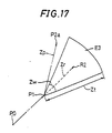
The present invention is also characterized in that the
predicted coordinate area is a sector area having a radius of
a predetermined length and a central angle of a predetermined
degree and that a line segment having both ends of the defined
latest coordinate and the predicted coordinate passes through
the center of an imaginary circle containing an arc of the
sector area.
According to the present invention, the predicted
coordinate area is a sector area containing the predicted
coordinate. The position of the future input point changes
from the position very close to the latest input point to the
position distant from the latest input point, exceeding the
predicted point, depending on a curve drawn at this time. When
a curve is to be drawn, the closer the future input point to
be inputted is to the latest input point, the closer the
straight line which passes through the latest input point and
the past input point becomes, and the farther it is, it is
considered to be inclined to separate in the direction vertical
to the straight line from the aspect of the straight line.
Therefore, the input point which may be inputted in the future
is considered to distribute so as to form a sector having the
center point on the line segment having both ends of the
predicted coordinate and the latest input point.
By adopting such sector area as the predicted coordinate
area, many points which may be inputted may be contained in
the area. Therefore, even if a valid coordinate is coordinate
of either a point very close to the latest input point or a
point considerably distant, the erroneous input
discriminating means can determine that coordinate as the valid
coordinate without mistake in the discrimination of erroneous
input. Accordingly, the error of the discrimination of
erroneous input may be reduced by using the sector area as the
predicted coordinate area.
The present invention is also characterized in that the
erroneous input discriminating means comprises;
According to the present invention, the erroneous input
discriminating means determines whether the input point is an
erroneous input or not based on the difference between the
predicted coordinate of the predicted point and the coordinate
of the input point which corresponds to the predicted point.
When the coordinate of the latest input point is sampled
and outputted and when the predicted coordinate is defined,
the error detecting means finds the distance between the input
point and the predicted point as an error between the latest
coordinate and its predicted coordinate. The predicted
coordinate which corresponds to the latest coordinate is found
in advance going back to the past from the latest sampling for
example.
The discriminating means determines whether the error
found by the error detecting means is less than the above-mentioned
predetermined distance. That is, it is determined
whether the line segment having the both ends of the predicted
point and the input point stays within the predicted coordinate
area. The discriminating means determines that the latest
coordinate is valid only when the error is less than the
predetermined distance.
The computing operation for the discrimination may be
simplified by discriminating whether the coordinate of the
input point is valid or not based on the error between the
predicted point and the input point as described above.
Therefore, because the burden of the discriminating operation
may be reduced, the burden on the circuit is small even if the
processing circuit provided in the present electronic
equipment is caused to perform this discriminating operation.
Accordingly, it may be implemented readily.
The present invention is also characterized in that the
two-dimensional coordinate input means outputs a status signal
indicative of that the coordinate has been outputted every time
of outputting two-dimensional coordinate, that the coordinate
input apparatus further comprises a delay circuit for delaying
the status signal by a predetermined delay time necessary for
outputting coordinates of a predetermined number of points used
in defining the predicted coordinate area from the two-dimensional
coordinate input means and for outputting the
status signal to the coordinate defining means and that the
coordinate defining means defines the coordinate only when the
status signal is supplied.
According to the present invention, the two-dimensional
coordinate input means outputs the status signal every time
of outputting two-dimensional coordinate. This status signal
indicates that the two-dimensional coordinate has been
normally sampled by the input means. The status signal is
supplied to the coordinate defining means after being delayed
by the predetermined time by the delay circuit. Accordingly,
a status signal at the time of sampling going back by the
predetermined delay time from the sampling when the latest
coordinate is obtained is supplied to the coordinate defining
means. The coordinate defining means defines the coordinate
only when the status signal is supplied and reject it when no
status signal is supplied. Accordingly, when a line is to be
inputted, all the coordinates are rejected from the input point
which corresponds to the beginning of drawing until when a
predetermined number of defined input points are inputted.
As described above, the coordinate predicting means
defines the predicted coordinate area by using a plurality of
defined coordinates which are the past coordinates older than
the latest coordinate to be discriminated. Accordingly, it
cannot define the predicted coordinate area until when a
required number of coordinates are defined and obtained from
the beginning of the inputted of the coordinate in inputting
a curve for example. According to the coordinate input
apparatus of the invention, the definition of the coordinate
is stopped until when the predicted coordinate area is
obtained. Thereby, because the coordinate is not outputted
until when the predicted coordinate is obtained and the
coordinate predicting operation is allowed, only coordinates
which are assured to be correct may be defined and outputted.
The present invention is also characterized in that the
erroneous input discriminating means determines whether the
coordinate is valid or not only when the status signal outputted
from the delay circuit is supplied, that the delay circuit is
constructed so that the output from the erroneous input
discriminating means is supplied thereto, that the same number
of memory elements with the predetermined number are connected
sequentially so that the outputs thereof are transferred to
the next memory elements and the outputs of the previous memory
elements are supplied per predetermined period and that each
memory element stores each status signal individually and
erases its memory content when the coordinate is determined
to be invalid by the erroneous input discriminating means.
According to the present invention, the two-dimensional
coordinate input means outputs the status signal indicative
of that the coordinate has been outputted every time of
outputting two-dimensional coordinate. This status signal is
supplied to the erroneous input discriminating means and the
coordinate defining means after being delayed by the
predetermined delay time by the delay circuit. The erroneous
input discriminating means performs the erroneous input
discriminating operation only when the status signal is
supplied in addition to the input point and the predicted
coordinate area.
The delay circuit is constructed so that the memory
elements which are registers for example are connected
sequentially so that the output thereof is supplied to the next
memory elements and so that the output of the previous memory
elements are supplied. The status signal output during the
sampling is stored individually to each memory element.
Therefore, when the sampling operation is started, the status
signal stored in each memory element is transferred to the later
memory element sequentially stage by stage and the status
signal outputted from the last memory element is supplied to
the erroneous input discriminating means and the coordinate
defining means.
The same number of memory elements with the number of
points used for defining the predicted coordinate area are
prepared. Therefore, the status signal inputted to the delay
circuit is transferred to each stage per each sampling
operation performed periodically. Accordingly, the status
signal inputted to the delay circuit is outputted after being
delayed by a length of time obtained by multiplying the period
of the sampling operation with the number of memory elements.
Accordingly, the circuit structure of the delay circuit may
be readily made.
When the coordinate is determined to be invalid by the
erroneous input discriminating means, each memory element
erases its memory content to be initialized. The state in
which each memory element is initialized is the same with the
state in which no input point is inputted from the two-dimensional
coordinate input means. Accordingly, when a new
coordinate is inputted following to a coordinate determined
to be invalid, the delay circuit inputs the status signal
outputted from the two-dimensional coordinate input means when
the new coordinate is inputted to the first memory element and
transfers it sequentially to the last memory element.
In the coordinate input apparatus, the discriminating
operation of erroneous input is performed by determining the
predicted coordinate area by using a plurality of defined
coordinates older than the latest coordinate to be
discriminated as described above. When an erroneous input
occurs, there is a case when the erroneous input discriminating
operation cannot be performed because the predicted coordinate
area cannot be found. At this time, because each memory
element of the delay circuit is initialized, no status signal
is stored in the delay circuit similarly to the point of time
when the coordinate of a line is started to be inputted. The
defining step in the coordinate defining means may be stopped
until when enough defined coordinates which allow the predicted
coordinate area to be obtained again can be obtained from when
the erroneous input has occurred.
Further, when the erroneous input occurs once as
described above, the future predicted coordinate area cannot
be obtained correctly. At this time, an error occurs in the
discriminating operation and there is a case when an input is
determined to be an erroneous input and the delay circuit is
reset even though the input is correct. In the coordinate
input apparatus of the invention, the erroneous input
discriminating means is also caused to perform the
discriminating operation only when the status signal is
supplied from the delay circuit. Thereby, when enough defined
coordinates which allow the predicted coordinate area to be
found are obtained, the status signal is outputted always from
the delay circuit. Accordingly, the erroneous input
discriminating operation may be performed only when the
predicted coordinate area is assured by performing the
processing operation only when the status signal is obtained.
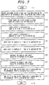
BRIEF DESCRIPTION OF DRAWINGS
other and further objects, features, and advantages of
the invention will be more explicit from the following detailed
description taken with reference to the drawings wherein:
DESCRIPTION OF PREFERRED EMBODIMENTS
Now referring to the drawings, preferred embodiments
of the invention are described below.
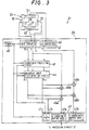
FIG. 1 is a block diagram showing a structure of an
electronic equipment 22 comprising a coordinate input
apparatus 21 which is a first embodiment of the present
invention. The electronic equipment 22 is realized by a
personal computer or a word processor for example.
The coordinate input apparatus 21 comprises a tablet
24 and a tablet control circuit 25. The tablet 24 is called
also as a touch panel. The electronic equipment 22 comprises
a processing circuit 27 and a display unit 28, beside the
coordinate input apparatus 21.
The coordinate input apparatus 21 detects an input point
inputted from the tablet 24 and outputs its two-dimensional
coordinate. The user of the electronic equipment 22 contacts
a pointing member which is a finger or a pen with the tablet
24 to press it down. The pressed point is inputted as the input
point. The tablet 24 is placed right above a visual display
area which is a flat two-dimensional plane of the display unit
28. The tablet 24 is a translucent flat and plane member.
Accordingly, contents displayed on the visual display area of
the display unit 28 may be seen through the tablet 24.
The tablet 24 is realized by a resistor film type tablet,
for example. Beside the tablet of such a type, there are ones
of electrostatic capacity type, optical type and ultrasonic
type, depending on the structure thereof. Any type of tablet
may be used for the tablet 24 of the present embodiment. The
structure of the resistor film type tablet for example will
be explained below.
The resistor film type tablet has two transparent
electrode members each of which is obtained by forming a
translucent conductive film on one surface of a transparent
member. The transparent member is formed of a translucent and
flexible plastic or resin. In the tablet 24, such pair of
transparent electrode members is disposed so that one surface
on which the transparent conductive film is formed face each
other while leaving a space therebetween. A dot spacer which
is made of insulating fine particle is disposed on one surface
of either one of the transparent electrode members to interpose
between the transparent electrode members. The dot spacer
keeps the space between the two transparent electrode members
and prevents the transparent conductive films which face each
other from contacting when no input point is inputted.
When the other surface of either one of the transparent
electrode members of the tablet is pressed down, the
transparent conductive films of the two transparent electrode
members contact and are shorted. The resistor film type tablet
detects the two-dimensional coordinate which corresponds to
the pressed point by utilizing this short.
Among the electrostatic capacity type tablets, there
is an analog electrostatic capacity type tablet. This tablet
is constructed by forming a glass panel by forming a transparent
conductive film having a uniform resistivity on one surface
of a transparent member and by connecting an element which
applies the same voltage to the whole surface of the glass panel
at the edge of the panel. When a conductor such as a finger
of a user touches with the transparent conductive film of the
glass panel, the transparent conductive film is grounded via
the conductor and the user having the conductor. Thereby, a
small amount of current flows through the transparent
conductive film. The small amount of current is detected by
two pairs of detecting means provided at the peripheral edges
of the glass panel vertically to each other to obtain the
coordinate of position of the input point from the values of
the current.
The tablet 24 outputs an analog output which corresponds
to the coordinate of position of the input point. The analog
outputted from the tablet 24 is supplied to the tablet control
circuit 25. The tablet control circuit 25 converts the output
from the tablet 24 into digital values and implements the
discrimination of erroneous input to discriminate whether the
input coordinate value is correct or not as described later.
The output from the tablet control circuit 25 is supplied to
the processing circuit 27 which implements processing based
on the coordinate values thus supplied. For example, it
inverts pixels within the visual display area which correspond
to the coordinate values, i.e. pixels in the visual display
area right below the point of the tablet 24 thus operated, from
white display to black display to display on the display unit
28.
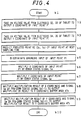
FIG. 2 is a flowchart for explaining an input
discriminating operation performed in the tablet control
circuit 25. The user presses down the tablet 24 by using a
pointing member such as a pen or a finger in the same manner
of drawing a curve on a paper by a writing tool to input an
input point. When input points are inputted continuously, the
tablet control circuit 25 of the present embodiment implements
the discrimination of erroneous input on the latest input point
to be inputted anew by using an input point which has been
discriminated to be valid among input points inputted in the
past.
When the electronic equipment 22 is turned on for
example, the process advances from Step a1 to Step a2. At Step
a2, it is determined whether the input point has been inputted
to the tablet 24. That is, it is determined whether a
predetermined change has occurred in the analog output from
the tablet 24. For example, the level of the analog output
when no input point is inputted is smaller than the level of
the analog output when an input point is inputted. This
determination is made during a sampling operation of the analog
output performed per predetermined period T for example. When
there is no input, the process returns to Step a2 and this
determination is repeated until when an input is made. When
there is an input, the process advances from Step a2 to Step
a3.
At Step a3, a coordinate predicting operation is carried
out based on the coordinate of the latest input point inputted
during the present sampling operation. In the coordinate
predicting operation, a predicted coordinate which is assumed
to be inputted during the future sampling operation at the time
advanced by the same time with the period T from the sampling
operation when the latest input point has been inputted is
found. The coordinate predicting operation will be detailed
later. After finishing the coordinate predicting operation,
the process advances from Step a3 to Step a4. At Step a4, an
erroneous input discriminating operation is performed. In the
erroneous input discriminating operation, it is determined
whether the latest input point is an erroneous input or not
based on the predicted coordinate predicted during the latest
sampling operation going back to the same time with the period
T from the present sampling operation. The discrimination
result of the erroneous input discriminating operation is
outputted as an error status signal. The erroneous input
discriminating operation will be detailed later.
After finishing the erroneous input discriminating
operation at Step a4, the process advances to Step a5. At Step
a5, it is determined whether the coordinate of the latest input
point is valid or not based on the discrimination result of
the erroneous input discriminating operation. When it is
valid, the process advances from Step a5 to Step a6. At Step
a6, the coordinate of the latest input point is transferred
to the processing circuit 27 as it is, in addition of the error
status signal. The processing circuit 27 operates based on
the coordinate and the signal. The error status signal at this
time indicates that the latest input point is not erroneous.
The coordinate determined to be valid will be referred to as
"valid coordinate" hereinafter.
When the coordinate of the latest input point is
determined to be invalid and the input is an erroneous input,
the process advances from Step a5 to Step a7. At Step a7, an
error processing is performed. In the error processing, the
coordinate of the latest input point is changed to a
predetermined coordinate (0, 0) for example to transfer to the
processing circuit 27. Hereinafter, the coordinate which is
determined to be invalid will be referred to as "invalid
coordinate". In the same time, an error status signal
indicative of that the coordinate has been erroneous inputted
is transferred to the processing circuit 27. Further, a
register is reset to return the tablet control circuit 25 to
the initial state as described later. The processing circuit
27 operates based on the coordinate and the signal thus
transferred. After finishing the transfer step pertaining to
the coordinate of the latest input point at Steps a6 and a7,
the process returns to Step a2 to perform the input determining
operation on the next latest input point to be inputted after
the period T.
Thereby, the coordinate and the error status signal
concerning to the latest input point inputted from the tablet
24 are inputted to the processing circuit 27 per the period
T for example. The processing circuit 27 causes the display
unit 28 to visually display the coordinate of the input point
when the error status signal indicates that the input point
is not an erroneous input and that the coordinate is valid.
Assume that the display unit 28 is a display unit which displays
in black and white. At this time, the coordinate of the latest
input point is displayed by inverting the display color from
the original display color of pixels at position corresponding
to the coordinate on the visual display area of the display
unit 28. When the input points are inputted continuously for
example, the processing circuit 27 causes the display unit 28
to display on the visual display area by inverting the display
color of all pixels positioned on a line segment having, as
both ends thereof, the latest input point and the input point
at the latest sampling is past whose coordinates are valid.
Thereby, when a plurality of input points are inputted
continuously, a curve approximated by broken lines in which
those input points are connected in series is drawn on the
display unit 28.
When the error status signal indicates that the input
point is an erroneous input and that the coordinate is invalid,
the processing circuit 27 stops displaying the given
coordinate. When the input points are inputted continuously
and when a valid coordinate is transferred again after
transferring an invalid coordinate, the processing circuit 27
inverts and displays the display color of all pixels positioned
on a line segment having, as both ends thereof, a valid
coordinate transferred before the invalid coordinate and the
valid coordinate transferred later. Thereby, a curve
approximated by broken lines in which remaining input points
are connected in series, except of the invalid coordinate.
FIG. 3 is a block diagram showing a concrete structure
of the coordinate input apparatus 21 in FIG. 1. The tablet
24 is realized by the analog resistor film type tablet for
example.
The tablet 24 comprises a pair of transparent electrode
members in which a uniform transparent conductive film is
formed on one surface thereof. This transparent electrode
member deforms when pressure above a predetermined pressure
value is applied for example. Electrodes 32 and 33 are mounted
at both ends of the transparent conductive film of one
transparent electrode member in the Y direction indicated by
an arrow 37. Further, electrodes 34 and 35 are mounted at both
ends of the transparent conductive film of the other
transparent electrode member in the X direction indicated by
an arrow 38. These pair of transparent electrode members are
disposed so that one surface thereof on which the transparent
conductive film is formed face each other while leaving a
predetermined space therebetween. The space between the
transparent conductive films of one and the other transparent
electrode members is kept by a dot spacer made of insulator
for example.
A flat and rectangular pointing area 31 is formed on
the tablet 24. The pointing area 31 is an area where the
transparent conductive films in the part surrounded by the
electrodes 32 through 35 face each other while leaving the space
in the pair of transparent electrode members thus provided.
The user presses down a point within the pointing area 31 by
the pointing member, i.e. the finger or the pen, to input an
input point. At this time, the user performs either point
input or line input.
The tablet control circuit 25 samples voltage values
between the electrodes 32, 33 and the electrodes 34, 35 per
the predetermined period T. In inputting a point, one point
within the pointing area 31 is continuously pressed down. In
inputting a line, the pointing member is moved in the horizontal
direction in parallel with the surface of the tablet 24 while
pressing the tablet 24. In either case of the point input and
the line input, the time during which the tablet is pressed
down in one time of input is longer than at least three periods
of the period T for sampling the output from the tablet 24.
Therefore, the coordinate of the input point is sampled at least
three times during one time of input.
When the tablet 24 is pressed down by the pointing
member, the transparent conductive films of one and the other
transparent electrode members causes a short circuit at that
position. In detecting this position, either one pair of
electrodes among the electrodes 32, 33 and the electrodes 34,
35 are used as scan electrodes and the other pair of electrodes
are used as detection electrodes in one detection timing.
Predetermined gradient voltage is applied between one pair of
electrodes to be used as the scan electrodes. The gradient
voltage is divided at the part where the transparent conductive
films has shorted and the detection electrodes detect the
divided voltage. The ratio of division of the gradient voltage
is equal to a ratio of division by which a distance between
the scan electrodes is divided at the input point.
Accordingly, the ratio of division of the gradient voltage is
found from the values of divided voltages detected from the
detection electrodes and the coordinate of position of the
input point in one direction in which the scan electrodes are
disposed is obtained from this ratio.
When the electrodes 32, 33 are used as the detection
electrodes and the electrodes 34, 35 are used as the scan
electrodes as described above, the electrodes 32, 33 detect
a voltage value which corresponds to the coordinate of the input
point in the X direction. When the electrodes 32, 33 are used
as the scan electrodes and the electrodes 34, 35 are used as
the detection electrodes in contrary, the electrodes 34, 35
detect a voltage value which corresponds to the coordinate of
the input point in the Y direction. The electrodes 32, 33 and
the electrodes 34, 35 are switched as the scan electrodes and
detection electrodes in a very short time. The values of the
voltages detected respectively in the electrodes 32, 33 and
the electrodes 34, 35 are supplied to the tablet control circuit
25 as the analog outputs from the tablet 24. The tablet control
circuit 25 converts the analog outputs output from the tablet
24 into digital values and performs the discrimination of
erroneous input to determine whether the input is an erroneous
input or not.
The tablet control circuit 25 comprises analog/digital
converter circuits 41 and 42, a coordinate predicting circuit
43, an erroneous input discriminating circuit 44, multipliers
45a, 45b; 46a, 46b, a buffer 47 and a timer 48. Operation timing
of each of the circuits 41 through 44, multipliers 45a, 45b;
46a, 46b and the buffer 47 is controlled by the timer 48. The
timer 48 derives an activation output which instructs an
activation of each of the components 41 through 47 with respect
to each of the components 41 through 47 every time when the
time of one period of the predetermined period T passes. Given
the activation output, each of the components 41 through 47
is activated and processes the signal given to each.
Hereinafter, the time of one period of the period T will be
referred to as "time T".
In the following explanation, each of the components
of the tablet control circuit 25 is assumed to be activated
sequentially at times t0, t1 and t2. The interval between the
times t0, t1 and t2 is the time T and it is assumed that input
points P0, P1 and P2 are inputted from the tablet 24 at those
times t0, t1 and t2, respectively. The past input point P0
is an input point at time t0 going back from time t1 by the
time T. The latest input point P1 is an input point at time
t1. The future input point P2 is an input point at time t2
advanced from time t1 by the time T. The coordinate of the
past input point P0 is assumed to be a valid coordinate which
is determined to be valid in the erroneous input discriminating
circuit 44 described later. At this time, the coordinate of
a past output point Q0 at time t0 stored in the buffer 47 is
equal to the coordinate of the input point P0.
FIG. 4 is a flowchart for explaining a processing
operation in the tablet control circuit 25 in detail. The
explanation will be made with reference to both FIGs. 3 and
4. The operation which will be explained below is assumed to
be performed at time t1.
When the activation output is derived at time t1, the
process advances from Step b1 to Step b2. At Step b2, the
analog/digital converter circuit 41 of a sampling circuit 40
samples a voltage value, i.e. an analog value, which is detected
when the electrodes 32, 33 are used as the detection electrodes
to convert into a digital value. The digital value of the
voltage value of the electrodes 32, 33 sampled at time t1 is
assumed to be X coordinate X1 of the coordinate of the latest
input point P1. The X coordinate X1 of the latest input point
P1 is supplied to the coordinate predicting circuit 43 and the
multiplier 45a. when the X coordinate X1 of the input point
P1 is output, the process advances from Step b2 to Step b3.
At Step b3, the analog/digital converter circuit 42 of
the sampling circuit 40 samples a voltage value which is
detected when the electrodes 34, 35 of the tablet 24 are used
as the detection electrodes to convert it from analog to
digital. The digital value of the voltage value of the
electrodes 34, 35 sampled at time t1 is assumed to be Y
coordinate Y1 of the coordinate of the latest input point P1.
The X coordinate X1 and the Y coordinate Y1 are detected
actually at different timings shifted from each other by a very
small period of time from time t1. The Y coordinate Y1 of the
latest input point P1 is supplied to the coordinate predicting
circuit 43 and the multiplier 45b. When the Y coordinate Y1
of the input point P1 is output, the process advances from Step
b3 to Step b4.
Further, when the sampling circuit 40 succeeds in
sampling the coordinate (X1, Y1) of the latest input point P1,
it outputs a sampling status signal Ss which indicates that
to the coordinate predicting circuit 43. The signal Ss takes
a value of either "1" or "0". The signal Ss becomes "1" when
the tablet 24 is pressed and becomes "0" when it is not. The
sampling status signal Ss is handled as a pen-down status signal
Sd1 at time t1 in the components 43 through 47 which follow.
At Step b4, a predicted point R2 (Xp, Yp) of the future
input point P2 at time t2 is found in the coordinate predicting
circuit 43 after passing by the time T from time t1. The valid
coordinate (X0, Y0) of the past input point P0 has been stored
in the coordinate predicting circuit 43 in advance. When the
past input point P0 is supplied to the coordinate predicting
circuit 43, the values of the coordinate of the output point
Q0 output from the tablet control circuit 25 are equal with
that of the input point P0 and are (X0, Y0).
The predicted coordinate (Xp, Yp) of the predicted point
R2 at time t2 is found based on the coordinate (X1, Y1) of the
input point P1 at time t1 and the coordinate (X0, Y0) of the
input point P0 at time t0 by the method described later. The
predicted point R2 (Xp, Yp) thus found is supplied to the
erroneous input discriminating circuit 44 to be used for the
discrimination of erroneous input at time t2. Further, in this
coordinate predicting operation, the coordinate predicting
circuit 43 derives a pen-down status signal Sd0 at time t0 from
the sampling circuit 40 at time t0 to the erroneous input
discriminating circuit 44. In the same time, it stores a
pen-down status signal Sd1 at time t1 from the sampling circuit
40 to a register described later. When the predicted
coordinate (Xp, Yp) of the predicted point R2 is output, the
process advances from Step b4 to Step b5.
At Step b5, the erroneous input discriminating circuit
44 performs the error input discriminating operation of the
latest input point P1 and outputs an error status signal Se1
at time t1 which indicates the discrimination result. The
predicted coordinate of the predicted point R1 of the input
point P1 is found by the coordinate predicting circuit 43 during
the input discriminating operation at time 0, i.e. at the
sampling time of one period before. The method how to
discriminate an erroneous input will be described later.
The error status signal Se assumes an either value of
"1" or "0". When the coordinate (X1, Y1) of the latest input
point P1 is determined to be a correct valid coordinate at time
t1, the error status signal Se1 turns out to be "1". When the
latest input point P1 is determined to be an erroneous input
and is an invalid coordinate, the error status signal Se1 turns
out to be "0". The output from the erroneous input
discriminating circuit 44 is supplied to the multipliers 45a
and 45b, a register 47c of the buffer 47 and the coordinate
predicting circuit 43. Further, the error status signal Se1
is supplied also to the erroneous input discriminating circuit
44 itself as described later. When the discrimination of
erroneous input is finished, the process advances from Step
b5 to Step b6.
During the erroneous input discriminating operation,
the erroneous input discriminating circuit 44 also derives a
pen-down status signal Sd(-1) at time t(-1) given at time t0
to the multipliers 46a and 46b and a register 47d of the buffer
47. Time t(-1) is time going back from time t0 by the time
T. In the same time, the pen-down status signal Sd0 at time
t0 supplied from the coordinate predicting circuit 43 is stored
in a register described later. When the error status signal
Se1 at time t1 is "0" and the input point is determined to be
an erroneous input, the registers described later in which the
pen-down status signals Sd1 and Sd0 are stored is initialized
to zero the values to be stored.
At Step b6, a first definition step for defining or
converting the X coordinate X1 of the input point P1 by the
discrimination result of the erroneous input discriminating
operation is performed by the multiplier 45a. In the first
definition step of the X coordinate at time t1, the X coordinate
X1 of the input point P1 output from the analog/digital
converter circuit 41 is multiplied with the error status signal
Se1 at time t1 output from the erroneous input discriminating
circuit 44. Because the signal Se1 is "1" when the coordinate
(X1, Y1) of the latest input point P1 is valid coordinate, the
output of the multiplication in the multiplier 45a turns out
to be "X1". Because the signal Se1 is "0" when the coordinate
(X1, Y1) of the latest input point P1 is invalid coordinate,
the output of the multiplication in the multiplier 45a turns
out to be "0". The output from the multiplier 45a is supplied
to the multiplier 46a. When the first definition step of the
X coordinate X1 is finished, the process advances from Step
b6 to Step b7.
At Step b7, a first definition step for the Y coordinate
is carried out by the multiplier 45b. In the first definition
step for the Y coordinate at time t1, the Y coordinate Y1 of
the input point P1 output from the analog/digital converter
circuit 42 is multiplied with the error status signal Se1 at
time t1 from the erroneous input discriminating circuit 44.
When the signal Se1 is "1", the multiplier 45b outputs "Y1".
When the signal Se1 is "0", the multiplier 45b outputs "0".
The output of the multiplier 45b is supplied to the multiplier
46b. When the first definition step for the Y coordinate Y1
is finished, the process advances from Step b7 to Step b8.
That is, in the first definition operation in the
multipliers 45a and 45b, when the coordinate (X1, Y1) of the
input point P1 is valid coordinate, the coordinate is defined
as it is. When the coordinate (X1, Y1) is invalid coordinate,
the coordinate is converted to a predetermined coordinate (0,
0). Thereby, it becomes possible to prevent the coordinate
of the input point erroneously inputted from becoming a
coordinate of the output point.
At Step b8, a second definition step for determining
whether the X coordinate defined in the first definition step
should be output or not is carried out in the multiplier 46a.
In the second definition step for the X coordinate at time t1,
the values of coordinate output from the multiplier 45a is
multiplied with the pen-down status signal Sd(-1) at time
t(-1). The multiplier 46a outputs "X1" only when the X
coordinate is valid coordinate "X1" and the signal Sd(-1) is
"1". The multiplier 46a outputs "0" any time when the X
coordinate is invalid coordinate "0" or when the signal Sd(-1)
is "0". The output of the multiplier 46a is stored in an X
coordinate buffer area 47a of the buffer 47 as X coordinate
of a latest output point Q1 at time t1. When the second
definition step for the X coordinate is finished, the process
advances from Step b8 to Step b9.
At Step b9, a second definition step for the Y coordinate
is carried out in the multiplier 46b. In the second definition
step for the Y coordinate at time t1, the values of coordinate
output from the multiplier 45b is multiplied with the pen-down
status signal Sd(-1) at time t(-1). The multiplier 46b
outputs "Y1" only when the value of coordinate is valid
coordinate "Y1" and the signal Sd(-1) is "1". The multiplier
46b outputs "0" any time when the value of coordinate is invalid
coordinate "0" or when the signal Sd(-1) is "0". The output
of the multiplier 46b is stored in a Y coordinate buffer area
47b of the buffer 47 as Y coordinate of the latest output point
Q1 at time t1. When the operation for the Y coordinate is
finished, the process advances from Step b9 to Step b10, thus
ending the operation of the process of the flowchart.
That is, in the second definition operation in the
multipliers 46a and 46b, the defined coordinates are output
as they are only when the valid coordinates can be obtained
continuously in the input discriminating operation at times
t(-1), t0 and t1. When they cannot be obtained, the defined
coordinate is converted to the predetermined coordinate (0,
0) to be output.
The erroneous input discriminating operation of an
input point is carried out by using two valid coordinates
obtained by going back to the past from the time of input of
the coordinate to be discriminated. Therefore, the erroneous
input discriminating operation cannot be carried out when those
coordinates cannot be obtained. The multipliers 46a and 46b
output the valid coordinate only when the erroneous input
discriminating operation can be carried out. Accordingly, it
becomes possible to prevent the coordinate which is defined
in the multipliers 46a, 46b when the discrimination or
erroneous input cannot be carried out from being the coordinate
of the output point.
Thereby, when the input discriminating operation at
time t1 is finished, the X coordinate and Y coordinate of the
output point Q1 at time t1 are stored in the buffer areas 47a
and 47b of the buffer 47, respectively. When the coordinate
of the latest coordinate P1 is the valid coordinate and when
two or more valid coordinates are output continuously from the
past, the values of the coordinate (X1, Y1) sampled from the
analog output from the tablet 24 are stored as the coordinate
of the output point Q1 as it is. When the latest coordinate
P1 is the point erroneously inputted or when a number of valid
coordinates output continuously in the past is less than 2,
(0, 0) is stored as the coordinate of the output point Q1. The
pen-down status signal Sd(-1) at time t(-1) and the error status
signal Se1 at time t1 are also stored in the registers 47c and
47d of the buffer 47.
The processing circuit 27 reads the contents stored in
each of the buffer areas 47a through 47d of the buffer 47. At
this time, it sets the values stored in the areas 47a and 47b
as the values of coordinate of the output point Q1 to be
processed only when the values of the signals Sd and Se in the
areas 47c and 47d are both "1". That is, the coordinate which
is the output of the tablet 24 converted to the digital value
is supplied to the processing circuit 27 only when the
discrimination of an erroneous input is allowed and when the
coordinate of the input point is valid. When it is not the
case, the values of coordinate (0, 0) are given to the
processing circuit 27. It allows the coordinate erroneously
inputted to be eliminated. Further, although it is
conceivable that (0, 0) is output as a valid coordinate of an
input point, it is possible to distinguish the coordinate (0,
0) output when the coordinate is invalid coordinate and when
the discrimination of erroneous input is disallowed from the
coordinate (0,0) output when the coordinate is valid because
the both signals Sd and Se become "1" at this time.
The coordinate predicting circuit 43 finds the
predicted coordinate (Xp, Yp) of the predicted point R2 of the
next input point P2 based on the coordinate (X1, Y1) of the
latest input point P1 at time t1 and the coordinate (X0, Y0)
of the past input point P0 at time t0.
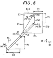
FIG. 6 is a diagram showing a relationship of positions
of the latest input point P1, the past input point P0, the future
input point P2 and the prediction point R2 of the input point
P2. The predicted point R2 is the position advanced from the
latest input point P1 by a distance d in the advance direction
indicated by an arrow 36. The advance direction is the
direction extending from the past input point P0 to the latest
input point P1. When a plurality of input points are inputted
continuously, this advance direction is equal with the tangent
direction of a curve drawn within the pointing area 31 at the
input point P0. The distance d is a distance from the past
input point P0 to the latest input point P1.
The predicted point R2 is the center point of a predicted
coordinate area E1 in which the future input point P2 should
exist. When the future input point P2 (X2, Y2) exists within
the quadrilateral predicted coordinate area E1, the erroneous
input discriminating circuit 44 determines that the values of
the coordinate of the input point is valid. This predicted
coordinate area E1 is a quadrilateral in which each side is
parallel with axes of coordinate of the coordinate system
showing the input point. That is, the sides E1a and E1b are
parallel with the axis of coordinate in the Y direction.
Similarly, the sides E1c and E1d are parallel with the axis
of coordinate in the X direction. In the tablet 24 of the
coordinate input apparatus 21, the coordinate system is an XY
orthogonal coordinate system. Accordingly, the predicted
coordinate area E1 turns out to be a rectangular area.
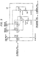
FIG. 5 is a block diagram showing a concrete structure
of the coordinate predicting circuit 43 of the tablet control
circuit 25 in Fig. 3. FIG. 7 is a flowchart for explaining
the coordinate predicting operation of the coordinate
predicting circuit 43 in FIG. 5. The explanation will be made
with reference to both FIGs. 5 and 7. The operation explained
below is assumed to be performed at time t1.
The coordinate predicting circuit 43 comprises a
register 52, buffers 53 and 54, subtracters 55 and 56 and adders
57 and 58. A sampling status signal Ss output from the sampling
circuit 40 is stored in the register 52 as a pen-down status
signal Sd. Values of coordinate sampled by the sampling
circuit 40 at the past sampling going back by one period of
time T are stored in the buffers 53 and 54. For instance, the
pen-down status signal Sd0 at time t0 and the coordinate (X0,
Y0) of the past input point P0 are stored in the register 52
as well as the buffers 53 and 54, respectively, just before
when the coordinate predicting operation at time t1 is carried
out.
When the timer 48 derives the activation output, the
process advances from Step c1 to Step c2. At Step c2, the
pen-down status signal Sd0 stored in the register 52 is output
to supply to a register 61 of the erroneous input discriminating
circuit 44. When the signal Sd0 is output, the process
advances to Step c3. At Step c3, the sampling status signal
Ss output from the sampling circuit 40 is stored in the register
52 as the pen-down status signal Sd1 at time t1. When the signal
Sd1 is stored, the process advances to Step c4. Due to this
operation, the pen-down status signal Sd given to the circuit
43 is output from the circuit 43 by being delayed by one period
of time T.
At Step c4, the X coordinate X1 of the latest input point
P1 sampled at time t1 is supplied to the subtracter 55 from
the analog/digital converter circuit 41. The X coordinate X1
of the input point P1 is also supplied to and stored in the
buffer 53. After supplying the X coordinate X1, the process
advances from Step c4 to Step c5. At Step c5, the Y coordinate
Y1 of the latest input point P1 sampled at time t1 is supplied
to the subtracter 56 from the analog/digital converter circuit
42. The Y coordinate Y1 of the input point P1 is also supplied
to and stored in the buffer 54. After supplying the Y
coordinate Y1, the process advances from Step c5 to Step c6.
At Step c6, X0 of the past input point P0 sampled at
time t0 is supplied to the subtracter 55 from the buffer 53.
After supplying the past X0, the process advances to Step c7.
At Step c7, Y coodinate Y0 of the past input point P0 is supplied
to the subtracter 56. After supplying the Y0, the process
advances to Step c8.
At Step c8, the X coordinate X0 of the past input point
P0 is subtracted from the X coordinate X1 of the latest input
point P1 in the subtracter 55 to find a value of difference
Xd:
Xd = X1 - X0
After obtaining the value of difference Xd, the value
Xd is supplied to the adder 57. After supplying the value of
difference Xd, the process advances to Step c9. At Step c9,
the Y coordinate Y0 of the past input point P0 is subtracted
from the Y coordinate Y1 of the past input point P1 in the
subtracter 56 to find a value of difference Yd:
Yd = Y1 - Y0
The value of difference Yd thus obtained is supplied
to the adder 58. After supplying the value of difference Yd,
the process advances to Step c10.
At Step c10, the value of difference Xd is added to the
X coordinate X1 of the latest input point P1 to obtain X
coordinate Xp of the predicted point R2:
Xp = Xd + X1
The X coordinate Xd of the predicted point R2 thus
obtained (hereinafter abbreviated as "predicted X
coordinate") is supplied to the erroneous input discriminating
circuit 44. After obtaining the predicted X coordinate Xd,
the process advances to Step c11. At Step c11, the value of
difference Yd is added to Y coordinate Y1 of the latest input
point P1 to obtain a Y coordinate Yp of the predicted point
R2 (hereinafter abbreviated as "predicted Y coordinate"):
Yp = Yd + Y1
The predicted Y coordinate Yp thus obtained is supplied
to the erroneous input discriminating circuit 44. After
obtaining the predicted Y coordinate Yp, the process advances
to Step c12, ending the operation of the process in the
flowchart.
When two or more input points are obtained in the past
continuously, the coordinate predicting circuit 43 thus
predicts the coordinate of position of the input point to be
obtained in the next sampling based on those input points
already obtained.
FIG. 8 is a block diagram showing a concrete structure
of the erroneous input discriminating circuit 44 in FIG. 3.
FIG. 9 is a flowchart for explaining the erroneous input
discriminating operation of the erroneous input
discriminating circuit 44. The explanation will be made below
with reference to both FIGs. 8 and 9. The discriminating
operation explained below is assumed to be performed at time
t2.
The erroneous input discriminating circuit 44 comprises
a register 61, subtracters 62 and 63, memories 64 and 65,
comparators 66 and 67 and multipliers 68 and 69. The register
61 stores the pen-down status signal Sd at the time of operation
going back by twice of time of the time T from the present input
discriminating operation. A predetermined X-axis error
allowance Xt and Y-axis error allowance Yt are stored in the
memories 64 and 65, respectively. For example, the pen-down
status signal Sd0 at time t0 is stored in the register 61 just
before time t2.
At time t2, the sampling circuit 40 samples values of
voltage between the electrodes 32, 33; 34, 35 at time t2 to
obtain values of coordinate (X2, Y2) of the input point P2.
The coordinate (X2, Y2) of the input point P2 is given to the
coordinate predicting circuit 43 to be used to determine a
predicted point of the input point at time t3 after passing
from time t2 by the time T. The erroneous input discriminating
circuit 44 determines whether the future input point P2 (X2,
Y2) is contained within the predicted coordinate area E1
centering on the predicted point R2 found by the coordinate
predicting circuit 43.
In the flowchart in FIG. 9, the process advances from
Step d1 to Step d2 when the activation output is derived from
the timer 48 at time t2. At Step d2, the pen-down status signal
Sd0 stored in the register 61 is output to be given to the
multipliers 46a and 46b as well as the register 47c described
before. The signal Sd0 is used in the second discrimination
process and in the process of the processing circuit 27. The
signal Sd0 is given also to the multiplier 69 of the erroneous
input discriminating circuit 44. After outputting the signal
Sd0, the process advances to Step d3. At Step d3, the pen-down
status signal Sd1 at time t1 output from the register 52 of
the coordinate predicting circuit 43 is stored to the register
61. After storing the signal Sd1, the process advances to Step
d4. Due to this operation, the pen-down status signal Sd given
to the erroneous input discriminating circuit 44 is output from
the circuit 44 by being delayed by one period of time T.
Thereby, the sampling status signal Ss output from the
sampling circuit 40 is used in the second discriminating step
after being delayed by two periods of time (2 x T) from the
sampling operation output from the sampling circuit 40 of the
circuits 43 and 44. Accordingly, the coordinate of the input
point P from the sampling circuit 40 is not output as the
coordinate of the output point Q unless valid coordinates of
the input points P are inputted at least three times
continuously. Accordingly, the output point Q is suppressed
until when the predicted coordinate R is predicted and the
discrimination of erroneous input is allowed.
At Step d4, the predicted X coordinate Xp output from
the adder 57 of the coordinate predicting circuit 43 is inputted
to the subtracter 62. Then, the process advances to Step d5.
At Step d5, the predicted Y coordinate Yp output from the adder
58 of the coordinate predicting circuit 43 is inputted to the
subtracter 63. Then, the process advances to Step d6. At Step
d6, the X coordinate X2 of the future input point P2 is inputted
from the analog/digital converter circuit 41 of the sampling
circuit 40 to the subtracter 62. Then, the process advances
to Step d7. At Step d7, the Y coordinate Y2 of the future input
point P2 is inputted from the analog/digital converter circuit
42 to the subtracter 63. Then, the process advances to Step
d8. Thereby, the X coordinate and the Y coordinate of the
predicted point R2 and the input point P2 are supplied to the
subtracters 62 and 63, respectively.
At Step d8, the predicted X coordinate Xp is subtracted
from the X coordinate X2 of the future input point P2 to find
an error Xe of the X coordinate:
Xe = X2 - Xp
The error Xe thus found is given to the comparator 66.
After determining the error Xe, the process advances to Step
d9. At Step d9, the predicted Y coordinate Yp is subtracted
from the Y coordinate Y2 of the future input point P2 to find
an error Ye of the Y coordinate:
Ye = Y2 - Yp
The error Ye thus found is given to the comparator 67.
After determining the error Ye, the process advances to Step
d10.
At Step d10, the X-axis error allowance Xt stored in
the memory 64 is supplied to the comparator 66. Then, the
process advances to Step d11. At Step d11, the Y-axis error
allowance Yt stored in the memory 65 is supplied to the
comparator 67. Then, the process advances to Step d12.
At Step d12, the error Xe in the X direction is compared
with the X-axis error allowance Xt in the comparator 66. Then,
the process advances to Step d13. At Step d13, it is determined
whether the absolute value |Xe| of the error Xe of the X
coordinate is less than the X-axis error allowance Xt. The
comparator 66 outputs an error output which indicates the
result of comparison of the absolute value |Xe| and the
allowance Xt. The error output assumes either value of "1"
or "0" in correspondence to the relationship of values of the
absolute value |Xe| and the allowance Xt.
That is, it is determined in the comparator 66 whether
the X coordinate X2 of the future input point P2 exists within
the range from the value (Xp - Xt) separated from the predicted
X coordinate Xp of the predicted point R2 at time t2 by the
X-axis error allowance Xt in the decremental direction of the
value of coordinate on the X coordinate axis to the value (Xp
+ Xt) separated from the predicted X coordinate Xp by the
allowance Xt in the incremental direction of the value of
coordinate. When the position of the coordinate P2 in the
X-axis direction is contained in the predicted coordinate range
E1 as shown in FIG. 6, the absolute value |xe| of the error
Xe in the X direction is less than the value of the X-axis error
allowance Xt.
Reference will be made again to FIGs. 8 and 9. When the
absolute value |Xe| of the error Xe of the X coordinate is less
than the X-axis error allowance Xt, the process advances from
Step d13 to Step d14. At Step d14, the error output whose value
is "1" is output from the comparator 66. This error output "1"
is supplied to the multiplier 68:
1 : Xt > |Xe|
When the absolute value |Xe| is the allowance Xt or more,
the process advances from Step d13 to Step d15. At Step d15,
the error output whose value is "0" is output from the
comparator 66 to the multiplier 68:
0 : Xt ≦ |Xe|
Thereby, when the future input point P2 exists within
the range pinched by the sides E1a and E1b with respect to the
X-axis direction indicated by an arrow 37 in FIG. 6, the
comparator 66 outputs the error output "1". When the input
point P2 exists out of the range with respect to the X-axis
direction, the error output "0" is output. When the error
output of "1" or "0" is output to the multiplier 68, the process
advances from Steps d14 and d15 to Step d16.
At Step d16, the error Ye in the Y direction is compared
with the Y-axis error allowance Yt in the comparator 67. Then,
the process advances to Step d17. At Step d17, it is determined
whether an absolute value |Ye| of the error Ye in the Y-axis
direction is less than the Y-axis error allowance Yt. The
comparator 67 outputs an error output which indicates the
result of comparison of the absolute value |Ye| and the
allowance Yt. The error output assumes either value of "1"
or "0" in correspondence to the relationship of values of the
absolute value |Ye| and the allowance Yt. When the position
of the coordinate P2 in the Y-axis direction is contained in
the predicted coordinate range E1, the absolute value |Ye| of
the error Ye of the Y coordinate is less than the value of the
Y-axis error allowance Yt as shown in FIG. 6.
When the absolute value |Ye| is less than the allowance
Yt, the process advances from Step d17 to Step d18 and the error
output "1" is output to the multiplier 68:
1 : Yt > |Ye|
When the absolute value |Ye| is the Y-axis error
allowance Yt or more, the process advances from Step d17 to
Step d19 and the error output "0" is output to the multiplier
68:
0 : Yt ≦ |Ye|
Thereby, when the future input point P2 exists within
the range pinched by the sides E1c and E1d with respect to the
Y-axis direction indicated by an arrow 38 as shown in FIG. 6,
the comparator 67 outputs the error output "1". When the input
point P2 is not contained there, the error output "0" is output.
When the error output of the Y coordinate is output to the
multiplier 68, the process advances from Steps d18 and d19 to
Step d20.
At Step d20, the error outputs of the X and Y coordinates
supplied from the comparators 66 and 67 are multiplied in the
multiplier 68. When the value of either one of the error
outputs of the X and Y coordinates is "0", the value obtained
as a result of the multiplication in the multiplier 68 turns
out to be "0". When the values of the error outputs of the
X and Y coordinates are both "1", the multiplication result
turns out to be "1". That is, the value obtained as a result
of the multiplication turns out to be "1" only when the absolute
value |Xe| of the error Xe of the X coordinate is less than
the X-axis error allowance Xt and when the absolute value |Ye|
of the error Ye of the Y coordinate is less than the Y-axis
error allowance Yt. The value turns out to be "0" in cases
other than that. The multiplication result of the multiplier
68 is given to the multiplier 69. After the multiplication,
the process advances from Step d20 to Step d21.
At Step d21, the multiplication result of the multiplier
68 is multiplied with the pen-down status signal Sd0 at time
t0 in the multiplier 69. This multiplication result is output
as an error status signal Se2 at time t2. The signal Se2 assumes
a value of either "1" or "0". The signal Se2 turns out to be
"1" only when the value of the multiplication result of the
multiplier 68 and the signal Sd0 are both "1". The signal Se2
turns out to be "0" when either of the value of the
multiplication result or the signal Sd0 is "0". When the error
status signal Se2 is output, thus ending the operation of the
process in the flowchart.
The error status signal Se2 is supplied to the
multipliers 45a, 45b of the tablet control circuit 25 and the
register 47d of the buffer 47 described above, respectively,
to be used for the first definition process and the process
in the processing circuit 27.
The error status signal Se2 is also supplied to the
registers 52 and 61 of the circuits 43 and 44. When the signal
Se2 is "0", those registers 52 and 61 are reset, thus storing
"0". Thereby, when it is determined in the erroneous input
discriminating circuit 44 that the input point P2 is inputted
erroneously, the values of the pen-down status signals Sd1 and
Sd2 during the previous and present sampling operations are
deleted. Therefore, when the erroneous input occurs, the
pen-down status signal Sd whose value is "1" is not supplied
to the multipliers 46a and 46b until when input points P of
effective coordinates are inputted twice again. Accordingly,
the coordinates of the input points P sampled at least two times
of operation are suppressed from being output from the next
operation of the sampling operation during which the erroneous
input has occurred. In the same time, the error status signal
Se whose value is "1" is suppressed from being outputted from
the erroneous input discriminating circuit 44.
The coordinate predicting circuit 43 finds the
predicted point R based on the two input points P sampled
continuously as described above. Therefore, when the
erroneous input occurs, the predicted point R used in two times
of sampling operation which is performed following to the
occurrence of the erroneous input is what is found using the
invalid coordinate of the input point P. At this time, there
may a case when the predicted point R itself is wrong.
Accordingly, there may be case when the discrimination result
of the erroneous input discriminating operation using those
predicted points R is wrong. The error status signal Se keeps
the value "0" at least until when the value of the pen-down
status signal Sd turns out to be "1". Thereby, it becomes
possible to prevent the coordinate of the input point P from
being defined as the coordinate of the output point Q as it
is until when the erroneous input discriminating operation can
be performed normally. Further, it becomes possible to
prevent the registers 52 and 61 from being reset again by the
error of the erroneous input discriminating operation.
In the erroneous input discriminating operation
described above, the error status signal Se2 turns out to be
"1" when the future input point P2 is contained within the
predicted coordinate area E1 centering on the predicted point
R2 as shown in FIG. 6. Further, when a future coordinate P2a
exists out of the predicted coordinate area E1, the error status
signal Se2 turns out to be "0" as shown in FIG. 10.
The predicted coordinate area E1 is a rectangular area
centering on the predicted point R2. Accordingly, the errors
of the error allowances Xt and Yt are permitted respectively
in the incremental and decremental directions of the values
of coordinate along the X-axis and Y-axis centering on the
coordinate (Xp, Yp) of the predicted point R2. Therefore, the
coordinate is determined to be valid even when a displacement
from the latest input point P1 to the future input point P2
is smaller than a displacement from the past input point P0
to the latest input point P1. A case of drawing a curve having
a large curvature may be cited as the case when the displacement
of the coordinate decreases.
FIG. 11 is a diagram showing input points P10, P11, P12
and P13 continuously inputted when a curve having a large
curvature is drawn and prediction points R12 and R13 of the
input points P12 and P13. A line segment Z1 has both ends of
the input points P10 and P11. A line segment Z2 has both ends
of the input points P11 and P12. A line segment Z3 has both
ends of the input points P12 and P13. At this time, a curve
in which an angle between the segments Z1 and Z2 and an angle
between the segments Z2 and Z3 are greater than 180 degrees
as shown in Figure and the segments Z1 through Z3 are connected
sequentially curves in the direction indicated by an arrow 36a.
At this time, the segments Z2 and Z3 separate considerably from
line segments represented by two-dot chain lines having both
ends of the input points P11 and P12, the origins thereof, and
predicted points R12 and R13. The segments Z2 and Z3 are also
shorter than the segment Z1. Accordingly, the displacement of
the coordinate of the input points P12 and P13 is smaller than
that of the input point P11.
At this time, a predicted coordinate area E13 of the
input point P13 extends also in the direction closer to the
input point P12 which is the past input point rather than the
predicted point R13. Accordingly, the input point P13 is
contained within the predicted coordinate area E13 even if the
displacement of the coordinate from the input point P12 to the
input point P13 is smaller than the displacement of the
coordinate from the input point P11 to the input point P12.
Further, when a curve is to be drawn, speed of moving
a pen drops by that degree in general, so that the displacement
of the coordinate becomes less. Accordingly, because the
predicted area E13 becomes closer to the input point P12, the
origin, the input point is readily included in the area even
if the displacement decreases.
It is possible to discriminate whether a coordinate of
an input point is valid or not even when a curve having a large
curvature is drawn by thus extending the predicted area E1 also
at the side of downstream in the advance direction of the input
points continuously inputted centering on the predicted
coordinate provided at a position where the line segment
connecting two past coordinates is extended.
A coordinate input apparatus of a second embodiment of
the present invention will be explained below. The coordinate
input apparatus of the present embodiment has the similar
structure with the coordinate input apparatus 21 of the first
embodiment except details of the structure of the erroneous
input discriminating circuit and the behavior thereof, the same
components of the coordinate input apparatuses are designated
by the same reference numerals and the detailed explanation
thereof will be omitted here. In the coordinate input
apparatus 21 of the present embodiment, a predicted area E2
is a circular area which is centered on the predicted point
R2 and whose radius is a predetermined length Lt. FIG. 13 shows
this predicted area E2.
The behavior of the tablet control circuit of the
coordinate input apparatus will be briefly described. The
tablet control circuit obtains coordinate of a latest input
point P1 from the tablet 24 per predetermined period T. The
coordinate predicting circuit 43 finds a predicted point R2
of a future input point P2 based on the coordinates of the past
and latest input points P0 and P1. An erroneous input
discriminating circuit 81 performs an erroneous input
discriminating operation described later based on the
predicted point R1 found during the previous sampling
operation. Coordinate of an output point Q1 is determined by
implementing a first definition step based on the error status
signal Se1 from the circuit 81 in the multipliers 45a and 45b
and a second definition step based on the pen-down status signal
Sd(-1) during the operation of two times before in the
multipliers 46a and 46b for the coordinate of the latest input
point P1. The processing circuit 27 causes the display unit
28 to display the output point only when the coordinate is valid
coordinate based on the coordinate of the output point Q1 and
the signals Sd(-1) and Se1. The coordinate predicting step,
the first and second definition steps and the processing in
the processing circuit 27 are equal to each step of the
coordinate input apparatus 21 in the first embodiment.
FIG. 12 is a block diagram showing a concrete structure
of the erroneous input discriminating circuit 81 of the
coordinate input apparatus described above. FIG. 14 is a
flowchart for explaining the erroneous input discriminating
operation in the erroneous input discriminating circuit 81.
The erroneous input discriminating circuit 81 has the similar
structure with the erroneous input discriminating circuit 44
in the first embodiment, so that the same components are
designated with the same reference numerals and a detailed
explanation thereof will be omitted here. The flowchart also
has the similar structure with the flowchart in FIG. 9. The
explanation will be made with reference to both FIGs. 12 and
14.
The erroneous input discriminating circuit 81 comprises
the register 61, the subtracters 62 and 63, squarers 83 and
84, an adder 85, a memory 86 and a comparator 87. The following
operation is assumed to be performed at time t2 for example.
At this time, the sampling circuit 40 samples and obtains
values of coordinate (X2, Y2) of the input point P2 at time
t2. The predicted point R2 of the input point P2 is found during
the input discriminating operation at time t1 going back from
time t2 by one period T.
The erroneous input discriminating circuit 81 is
activated when the activation output of the timer 48 is output
at time t2. When the circuit 81 is activated, the process
advances from Step e1 to Step e2. At Step e2, the pen-down
status signal Sd0 stored in the register 61 is output to be
given to the multipliers 46a and 46b as well as the register
47c. The signal Sd0 is used in the second discrimination
process and in the process of the processing circuit 27. The
signal Sd0 is given also to the multiplier 69 of the circuit
81. After outputting the signal Sd0, the process advances to
Step e3. At Step e3, the pen-down status signal Sd1 at time
t1 output from the register 52 of the coordinate predicting
circuit 43 is stored to the register 61. After storing the
signal Sd1, the process advances to Step e4. Due to this
operation, the pen-down status signal Sd given to the circuit
81 is output from the circuit 81 by being delayed by one period
of time T.
At Step e4, the predicted X coordinate Xp output from
the adder 57 of the coordinate predicting circuit 43 is inputted
to the subtracter 62. Then, the process advances to Step e5.
At Step e5, the predicted Y coordinate Yp output from the adder
58 of the coordinate predicting circuit 43 is inputted to the
subtracter 63. Then, the process advances to Step e6. At Step
e6, the X coordinate X2 of the future input point P2 is inputted
from the analog/digital converter circuit 41 of the sampling
circuit 40 to the subtracter 62. Then, the process advances
to Step e7. At Step e7, the X coordinate X2 of the future input
point P2 is inputted from the analog/digital converter circuit
42 of the circuit 40 to the subtracter 63. Then, the process
advances to Step e8.
At Step e8, the predicted X coordinate Xp is subtracted
from the X coordinate X2 of the future input point P2 to obtain
an error Xe of the X coordinate in the substrater 62:
Xe = X2 - Xp
The error Xe thus obtained is given to the squarer 83.
After obtaining the error Xe, the process advances to Step e9.
At Step e9, the value of the predicted Y coordinate Yp is
subtracted from the value of the Y coordinate Y2 of the future
input point P2 to obtain an error Ye of the Y coordinate in
the substrater 63 :
Ye = Y2 - Yp
The error Ye thus obtained is given to the squarer 84.
After obtaining the error Ye, the process advances to Step e10.
At Step e10, a square value Xe2 of the error Xe of the
X coordinate is obtained by the squarer 83 and is inputted to
the adder 85. Then, the process advances to Step e11. At Step
e11, a square value Ye2 of the error Ye of the Y coordinate
is obtained by the squarer 84 and is inputted to the adder 85.
Then, the process advances to Step e12. At Step e12, the square
values Xe2 and Ye2 of the X coordinate and the Y coordinate
are added to obtain a square error Le2 in the adder 85. The
square error Le2 is a square value of a distance Le from the
predicted point R2 to the future input point P2.
Le2 = Xe2 + Ye2
The square error Le2 is supplied to the comparator 87.
After obtaining the square error Le2, the process advances to
Step e13. At Step e13, a square error allowance Lt2 is read
from the memory 86 to input to the comparator 87. Then, the
process advances to Step e14. At Step e14, the square error
Le2 is compared with the square error allowance Lt2 in the
comparator 87. Then, the process advances to Step e15. The
square error allowance Lt2 is a square value of the
predetermined length Lt, i.e. the radius of the predicted area
E2 described above. The relationship between the
predetermined length Lt and the distance Le from the predicted
point R2 to the future input point P2 is equal to the
relationship between their square values.
At Step e15, it is determined whether the square error
Le2 is less than the square error allowance Lt2. When it is
the case, the future input point P2 is contained within the
predicted area E2 as shown in FIG. 13. Accordingly, when the
square error Le2 is determined to be less than the square error
allowance Lt2, the process advances to Step e16. At Step e16,
the comparator 87 outputs the error output "1" to the multiplier
69. Then, the process advances to Step e18.
1: Lt2 > Le2
When the value of the square error Le2 is the value of
the square error allowance Lt2 or more, the future input point
P2 is determined to be located out of the range of the predicted
area E2 as shown in FIG. 15. At this time, the process advances
from Step e15 to Step e17 to output the error output "0" to
the multiplier 69. Then the process advances to Step e18.
0: Lt2 ≦ Le2
At Step e18, the error output is multiplied with the
pen-down status signal Sd0 at time t0 in the multiplier 69.
This multiplication result is output as an error status signal
Se2 at time t2. The signal Se2 turns out to be "1" only when
the value of the error output and the signal Sd0 are both "1".
The value of the signal Se2 turns out to be "0" when either
of the value of the multiplication result or the signal Sd0
is "0". When the error status signal Se2 is output, the process
advances to Step e19, thus ending the operation of the process
in the flowchart.
The error status signal Se2 is supplied to the
multipliers 45a and 45b of the tablet control circuit 25 and
the register 47d of the buffer 47 described above,
respectively, to be used for the first definition process and
the process in the processing circuit 27. The error status
signal Se2 is also supplied to the registers 52 and 61 of the
circuits 43 and 44 to reset those registers 52 and 61 when the
input point P2 is an erroneous input.
Because the predicted range E2 is a circular area as
described above, only one time of operation for comparing the
error and the error allowance is required. Accordingly, the
discrimination of erroneous input in the erroneous input
discriminating circuit 81 may be readily performed.
A coordinate input apparatus of a third embodiment of
the present invention will be explained below. The coordinate
input apparatus of the present embodiment has the similar
structure with the coordinate input apparatus 21 of the first
embodiment except details of the structure of the erroneous
input discriminating circuit and the behavior thereof, the same
components of the coordinate input apparatuses are designated
by the same reference numerals and the detailed explanation
thereof will be omitted here. In the coordinate input
apparatus of the present embodiment, a predicted area E3 is
a sector area containing the predicted point R2 therein.
The behavior of the tablet control circuit of the
coordinate input apparatus will be briefly described. The
tablet control circuit obtains coordinate of a latest input
point P1 from the tablet 24 per predetermined period T. The
coordinate predicting circuit 43 finds a predicted point R2
of a future input point P2 based on the coordinates of the past
and latest input points P0 and P1. The erroneous input
discriminating circuit performs an erroneous input
discriminating operation described later based on the
predicted point R1 found during the previous sampling operation
(at time t0). Coordinate of an output point Q1 is determined
by implementing a first definition step based on the error
status signal Se1 from the circuit in the multipliers 45a and
45b and a second definition step based on the pen-down status
signal Sd(-1) during the operation of two times before (at time
t(-1)) in the multipliers 46a and 46b for the coordinate of
the latest input point P1. The processing circuit 27 causes
the display unit 28 to display the output point only when the
coordinate is valid coordinate based on the coordinate of the
output point Q1 and the signals Sd(-1) and Se1. The coordinate
predicting step, the first and second definition steps and the
processing in the processing circuit are equal to each step
of the coordinate input apparatus 21 in the first embodiment.
FIG. 16 is a diagram showing a predicted coordinate area
E3 in the erroneous input discriminating circuit of the
coordinate input apparatus described above. The predicted
coordinate area E3 is a sector area in which the predicted point
R2 is contained, a length of the radius is an allowable error
Zt and a degree of the a central angle is a predicted error
angle Zw. The center Zc of an imaginary circle containing the
sector arc of the predicted coordinate area E3 and the length
of the radius is the allowable error Zt is located on a position
on a line segment Zr having both ends of the latest input point
P1 and the predicted point R2 separated from the predicted point
R2 by a predetermined distance. This distance does not exceed
the allowable error Zt which is the length of the radius of
the imaginary circle and is equal to the length of the segment
Zr for example. The straight line containing the segment Zr
is a bisector of the allowable error angle Zw which is the
central angle of the predicted coordinate area E3 for example.
Therefore, the predicted point R2 is located on the straight
line passing through the allowable error angle Zw and coincides
with a point within the predicted coordinate area E3 separated
from the center Zc of the imaginary circle by the predetermined
distance.
The erroneous input discriminating circuit sets the
sector predicted coordinate area E3 based on the latest input
point P1 and the predicted point R2. The erroneous input
discriminating circuit determines whether the input point P2
is contained within the predicted coordinate area E3 on the
basis of the length of the segment Zp having the both ends of
the center Zc of the imaginary circle and the input point P2
and the angle formed between the segment Zp and the segment
Zt. The input point P2 is considered to be contained within
the predicted coordinate area E3 only when the length of the
segment Zp is less than the allowable error Zt and the angle
formed between the segment Zp and the segment Zr is less than
the half of the allowable error angle Zw.
When the future input point P2 (X2, Y2) is contained
within the input area E3, the input discriminating circuit
determines that the value of the coordinate of the input point
P2 is valid and outputs the error status signal Se whose value
is "1". The input point P2 in FIG. 16 shows the state when
the coordinate is valid coordinate. When the future input
point P2 is not contained within the input area E3, the circuit
determines that the value of coordinate of the input point P2
is invalid and outputs the error status signal Se whose value
is "0". The values of coordinate X2 and Y2 of the input point
P2 are defined or rejected in the first definition step in the
multipliers 45a and 45b based on the error status signal Se.
When a plurality of input points are inputted
continuously from the tablet 24, the user is drawing a curve
on the pointing area 31 of the tablet 24. Accordingly, a point
which can be inputted at time t2 is considered to be in the
vicinity of an extension line of the line segment having the
input points P0 and P1 near the input point P1. When the speed
for drawing the curve increases and an input point separates
from the input point P1 along the direction parallel with the
extension line, a range where the input point may exist is
considered to extend in the direction crossing at right angles
with the extension line. The extension line of the segment
contains the segment Zr having the both ends of the latest input
point P1 and the predicted point R2.
The further in the direction of drawing the curve from
the latest input point within the pointing area 31, the wider
the sector predicted coordinate area E3 becomes. Therefore,
the farther from the latest input point P1, the more a number
of points which can be valid coordinate increases in the
direction crossing at right angles with the segment Zr from
the predicted point R2. Accordingly, points which can be
inputted when the user draws a curve by inputting points of
coordinate may be contained more. Thereby, the input points
which are inputted continuously by drawing the curve may be
considered as valid coordinates without mistake.
The invention may be embodied in other specific forms
without departing from the sprit or essential characteristics
thereof. The present embodiments are therefore to be
considered in all respects as illustrative and not restrictive,
the scope of the invention being indicated by the appended
claims rather than by the foregoing description and all changes
which come within the meaning and the range of equivalency of
the claims are therefore intended to be embraced therein.