EP0816867B1 - Transducer element alignment structure in two dimensional array transducer for forming ultrasonic three dimensional images - Google Patents
Transducer element alignment structure in two dimensional array transducer for forming ultrasonic three dimensional images Download PDFInfo
- Publication number
- EP0816867B1 EP0816867B1 EP97304320A EP97304320A EP0816867B1 EP 0816867 B1 EP0816867 B1 EP 0816867B1 EP 97304320 A EP97304320 A EP 97304320A EP 97304320 A EP97304320 A EP 97304320A EP 0816867 B1 EP0816867 B1 EP 0816867B1
- Authority
- EP
- European Patent Office
- Prior art keywords
- transducer
- elements
- ring
- dimensional
- rings
- Prior art date
- Legal status (The legal status is an assumption and is not a legal conclusion. Google has not performed a legal analysis and makes no representation as to the accuracy of the status listed.)
- Revoked
Links
Images


Classifications
-
- A—HUMAN NECESSITIES
- A61—MEDICAL OR VETERINARY SCIENCE; HYGIENE
- A61B—DIAGNOSIS; SURGERY; IDENTIFICATION
- A61B8/00—Diagnosis using ultrasonic, sonic or infrasonic waves
-
- G—PHYSICS
- G01—MEASURING; TESTING
- G01S—RADIO DIRECTION-FINDING; RADIO NAVIGATION; DETERMINING DISTANCE OR VELOCITY BY USE OF RADIO WAVES; LOCATING OR PRESENCE-DETECTING BY USE OF THE REFLECTION OR RERADIATION OF RADIO WAVES; ANALOGOUS ARRANGEMENTS USING OTHER WAVES
- G01S15/00—Systems using the reflection or reradiation of acoustic waves, e.g. sonar systems
- G01S15/88—Sonar systems specially adapted for specific applications
- G01S15/89—Sonar systems specially adapted for specific applications for mapping or imaging
- G01S15/8906—Short-range imaging systems; Acoustic microscope systems using pulse-echo techniques
- G01S15/8909—Short-range imaging systems; Acoustic microscope systems using pulse-echo techniques using a static transducer configuration
- G01S15/8915—Short-range imaging systems; Acoustic microscope systems using pulse-echo techniques using a static transducer configuration using a transducer array
- G01S15/8922—Short-range imaging systems; Acoustic microscope systems using pulse-echo techniques using a static transducer configuration using a transducer array the array being concentric or annular
-
- G—PHYSICS
- G01—MEASURING; TESTING
- G01S—RADIO DIRECTION-FINDING; RADIO NAVIGATION; DETERMINING DISTANCE OR VELOCITY BY USE OF RADIO WAVES; LOCATING OR PRESENCE-DETECTING BY USE OF THE REFLECTION OR RERADIATION OF RADIO WAVES; ANALOGOUS ARRANGEMENTS USING OTHER WAVES
- G01S15/00—Systems using the reflection or reradiation of acoustic waves, e.g. sonar systems
- G01S15/88—Sonar systems specially adapted for specific applications
- G01S15/89—Sonar systems specially adapted for specific applications for mapping or imaging
- G01S15/8906—Short-range imaging systems; Acoustic microscope systems using pulse-echo techniques
- G01S15/8909—Short-range imaging systems; Acoustic microscope systems using pulse-echo techniques using a static transducer configuration
- G01S15/8915—Short-range imaging systems; Acoustic microscope systems using pulse-echo techniques using a static transducer configuration using a transducer array
- G01S15/8925—Short-range imaging systems; Acoustic microscope systems using pulse-echo techniques using a static transducer configuration using a transducer array the array being a two-dimensional transducer configuration, i.e. matrix or orthogonal linear arrays
-
- G—PHYSICS
- G01—MEASURING; TESTING
- G01S—RADIO DIRECTION-FINDING; RADIO NAVIGATION; DETERMINING DISTANCE OR VELOCITY BY USE OF RADIO WAVES; LOCATING OR PRESENCE-DETECTING BY USE OF THE REFLECTION OR RERADIATION OF RADIO WAVES; ANALOGOUS ARRANGEMENTS USING OTHER WAVES
- G01S15/00—Systems using the reflection or reradiation of acoustic waves, e.g. sonar systems
- G01S15/88—Sonar systems specially adapted for specific applications
- G01S15/89—Sonar systems specially adapted for specific applications for mapping or imaging
- G01S15/8906—Short-range imaging systems; Acoustic microscope systems using pulse-echo techniques
- G01S15/8993—Three dimensional imaging systems
Definitions
- the present invention relates to a transducer array for use in three dimensional ultrasonic scanning.
- ultrasonic diagnostic systems capable of providing three-dimensional images. Such systems might use mechanical means to scan in three-dimensions. However, these systems are complicated and require long scanning times. In fact, scanning times are so long that the image is influenced by the respiration of a patient. A solution might be for the patient to stop breathing while an ultrasonic image is taken, but the scanning times are too long. It is also difficult to obtain a reliable images due to the beating of the heart.
- a two-dimensional array transducer can be used.
- such a system becomes very complicated because several thousands of transducer elements are need to make up the two-dimensional array.
- transducer It has been proposed to make the transducer with a circular array of transducer elements, arranged in concentric rings, with the elements on each ring separated by the same length of arc.
- the transducer element pattern will exhibit n-fold rotational symmetry, where n is the largest number of elements common to all rings.
- n is the largest number of elements common to all rings.
- US-4586512 See US-4586512.
- the present invention seeks to improve upon this configuration of elements.
- a transducer array comprising first and second concentric rings of transducer elements for use in three dimensional ultrasonic scanning wherein a radial line passing through a first of the elements on the first ring does not pass through any of the elements on the second ring.
- the transducer array may include a third concentric ring of transducer elements, wherein the radial line does not pass through any of the elements on the third ring.
- the third ring may also be disposed radially outwardly of the first and second rings.
- the concentric rings may be separated by equal radial distances and for at least one of the rings, the elements thereof may be separated by the same circumferential length. Accordingly, the circumferential length may be the same for all rings.
- An ultrasonic imaging apparatus may include transducer elements.
- the polar field response of an array of transducers will show a main lobe, a side lobe and a grating lobe.
- the elements should be aligned so that the field of each element is randomly added near the main lobe rather than increasing the side lobe due to a random array of transducer elements.
- the elements are randomly aligned on circular grids thereby reducing a grating lobe while simultaneously preventing the level of the side lobe from rising.
- Figure 1 shows an element alignment structure for use in a two-dimensional array transducer.
- first, second and third, and outermost, rings 1, 2, 3 are arranged concentrically.
- a first set of transducer elements 10 are aligned, starting from a first transducer element 100.
- a second set of transducer elements 20 are aligned, starting from a second transducer element 200.
- a third set of transducer elements 30 are aligned, starting from a third transducer element 300.
- the spacing between a ring and its neighbour is the same for all rings and is marked RES.
- the spacing between each element on a ring is the same for all rings and is marked CES.
- CES is circumferential length between adjacent elements.
- a radial line 5 passes through the centre of the first transducer element 100.
- the second and third transducer elements 200, 300 are placed on their respective rings such that neither of them lie on the radial line 5.
- the second transducer element 200 is offset by a length of arc 6.
- Circular apertures are indicated by dotted lines. One circular grid is separated from another according to a predetermined relationship.
- the elements are located on the circles indicated by a solid line between the circular apertures.
- a first element is aligned to a location on each circle and the other elements are aligned to locations such that the circumferential distance between the elements are of the same length of arc.
- the distance between the elements on each circle is called the circular element spacing (CES).
- the distance between circles is called the radial element spacing (RES) and is a uniform distance.
- the first element is aligned to any location on each grid to obtain a smaller grating lobe. Since the elements uniformly distributed in the radial direction, the size of the side lobe does not increase.
- Figure 2 shows a two-dimensional transducer in which 499 elements are aligned using the alignment structure shown in Figure 1.
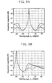
- Figures 3A and 3B show graphs of field response for a two-dimensional array transducer using the element alignment structure with different values of RES and CES.
- Figures 3A and 3B show the field response when a main lobe is located at an angle of 0° and -40° respectively.
- the solid lines in Figures 3A and 3B show field responses of the beams with respect to the array transducer composed of 499 elements having a RES of 1.4 ⁇ and a CES of 1.2 ⁇ when the centre frequency is 3.5 MHz and the diameter is 1.584 cm which corresponds to 38 ⁇ .
- the dotted lines show field responses of the beams with respect to the array transducer composed of 673 elements having a RES of 1.4 ⁇ and a CES of 1.2 ⁇ .
- the intermittent solid lines show field responses of the beams with respect to the array transducer composed of 703 elements having a RES of 1.2 ⁇ and a CES of 1.0 ⁇ .
- the dotted and intermittent lines show field responses of the beams with respect to the transducer composed of 877 elements having a RES of 1.4 ⁇ and a CES of 0.8 ⁇ .
- Figures 3A and 3B show that as the RES is reduced, the size of the side lobe is also decreased.
- the size of the grating lobe is decreased according to the CES value.
- the values of RES and CES are controlled through the element alignment structure, to reduce the magnitude of side lobe and the grating lobe.
- the array transducer comprised of 499 elements has a smaller grating lobe than that of the array transducer comprised of 625 elements.
- the element alignment structure reduces the number of the transducer elements needed in a two-dimensional array transducer to effectively form ultrasonic three-dimensional images.
Landscapes
- Physics & Mathematics (AREA)
- Engineering & Computer Science (AREA)
- Radar, Positioning & Navigation (AREA)
- Remote Sensing (AREA)
- Acoustics & Sound (AREA)
- Health & Medical Sciences (AREA)
- Life Sciences & Earth Sciences (AREA)
- Computer Networks & Wireless Communication (AREA)
- General Physics & Mathematics (AREA)
- Radiology & Medical Imaging (AREA)
- Animal Behavior & Ethology (AREA)
- Pathology (AREA)
- Biophysics (AREA)
- Biomedical Technology (AREA)
- Heart & Thoracic Surgery (AREA)
- Medical Informatics (AREA)
- Molecular Biology (AREA)
- Surgery (AREA)
- Nuclear Medicine, Radiotherapy & Molecular Imaging (AREA)
- General Health & Medical Sciences (AREA)
- Public Health (AREA)
- Veterinary Medicine (AREA)
- Ultra Sonic Daignosis Equipment (AREA)
- Measurement Of Velocity Or Position Using Acoustic Or Ultrasonic Waves (AREA)
- Image Analysis (AREA)
- Investigating Or Analyzing Materials By The Use Of Ultrasonic Waves (AREA)
- Image Processing (AREA)
Description
- The present invention relates to a transducer array for use in three dimensional ultrasonic scanning.
- Recently, ultrasonic diagnostic systems capable of providing three-dimensional images have been developed. Such systems might use mechanical means to scan in three-dimensions. However, these systems are complicated and require long scanning times. In fact, scanning times are so long that the image is influenced by the respiration of a patient. A solution might be for the patient to stop breathing while an ultrasonic image is taken, but the scanning times are too long. It is also difficult to obtain a reliable images due to the beating of the heart.
- To reduce the three-dimensional scanning time, a two-dimensional array transducer can be used. However, such a system becomes very complicated because several thousands of transducer elements are need to make up the two-dimensional array.
- It has been proposed to make the transducer with a circular array of transducer elements, arranged in concentric rings, with the elements on each ring separated by the same length of arc. The transducer element pattern will exhibit n-fold rotational symmetry, where n is the largest number of elements common to all rings. Such a device is shown in US-4586512. The present invention seeks to improve upon this configuration of elements.
- According to the present invention there is provided a transducer array comprising first and second concentric rings of transducer elements for use in three dimensional ultrasonic scanning wherein a radial line passing through a first of the elements on the first ring does not pass through any of the elements on the second ring.
- The transducer array may include a third concentric ring of transducer elements, wherein the radial line does not pass through any of the elements on the third ring. The third ring may also be disposed radially outwardly of the first and second rings. The concentric rings may be separated by equal radial distances and for at least one of the rings, the elements thereof may be separated by the same circumferential length. Accordingly, the circumferential length may be the same for all rings.
- An ultrasonic imaging apparatus may include transducer elements.
- A preferred embodiment of the present invention will now be described by way of example, with reference to the following drawings wherein:
- Figure 1 shows a transducer element alignment structure for use in a two-dimensional array transducer according to the present invention;
- Figure 2 shows a two-dimensional transducer in which 499 elements are aligned using the alignment structure shown in Figure 1; and
- Figures 3A and 3B show graphs of field response with respect to different values of RES and CES.
-
- The polar field response of an array of transducers will show a main lobe, a side lobe and a grating lobe. The elements should be aligned so that the field of each element is randomly added near the main lobe rather than increasing the side lobe due to a random array of transducer elements. In the present invention, the elements are randomly aligned on circular grids thereby reducing a grating lobe while simultaneously preventing the level of the side lobe from rising.
- Figure 1 shows an element alignment structure for use in a two-dimensional array transducer.
- Referring to Figure 1, first, second and third, and outermost,
rings 1, 2, 3 are arranged concentrically. On the first ring 1, a first set oftransducer elements 10 are aligned, starting from afirst transducer element 100. On thesecond ring 2, a second set oftransducer elements 20 are aligned, starting from asecond transducer element 200. Similarly, on the third, and outermost, ring 3, a third set oftransducer elements 30 are aligned, starting from athird transducer element 300. The spacing between a ring and its neighbour is the same for all rings and is marked RES. The spacing between each element on a ring is the same for all rings and is marked CES. CES is circumferential length between adjacent elements. Aradial line 5, passes through the centre of thefirst transducer element 100. The second andthird transducer elements radial line 5. Thus, thesecond transducer element 200 is offset by a length ofarc 6. - Circular apertures are indicated by dotted lines. One circular grid is separated from another according to a predetermined relationship. A circular aperture having a radius Ra is composed of Nc circles or dotted lines having the following equation:
- The elements are located on the circles indicated by a solid line between the circular apertures. A first element is aligned to a location on each circle and the other elements are aligned to locations such that the circumferential distance between the elements are of the same length of arc. The distance between the elements on each circle is called the circular element spacing (CES). The distance between circles is called the radial element spacing (RES) and is a uniform distance.
- In the element alignment structure of a two-dimensional array transducer shown in Figure 1, the first element is aligned to any location on each grid to obtain a smaller grating lobe. Since the elements uniformly distributed in the radial direction, the size of the side lobe does not increase.
- Figure 2 shows a two-dimensional transducer in which 499 elements are aligned using the alignment structure shown in Figure 1.
- Figures 3A and 3B show graphs of field response for a two-dimensional array transducer using the element alignment structure with different values of RES and CES. Figures 3A and 3B show the field response when a main lobe is located at an angle of 0° and -40° respectively.
- The solid lines in Figures 3A and 3B show field responses of the beams with respect to the array transducer composed of 499 elements having a RES of 1.4λ and a CES of 1.2λ when the centre frequency is 3.5 MHz and the diameter is 1.584 cm which corresponds to 38λ. The dotted lines show field responses of the beams with respect to the array transducer composed of 673 elements having a RES of 1.4λ and a CES of 1.2λ. The intermittent solid lines show field responses of the beams with respect to the array transducer composed of 703 elements having a RES of 1.2λ and a CES of 1.0λ. The dotted and intermittent lines show field responses of the beams with respect to the transducer composed of 877 elements having a RES of 1.4λ and a CES of 0.8λ.
- Figures 3A and 3B show that as the RES is reduced, the size of the side lobe is also decreased. The size of the grating lobe is decreased according to the CES value. Thus, the values of RES and CES are controlled through the element alignment structure, to reduce the magnitude of side lobe and the grating lobe. Also, the array transducer comprised of 499 elements has a smaller grating lobe than that of the array transducer comprised of 625 elements.
- As described above, the element alignment structure reduces the number of the transducer elements needed in a two-dimensional array transducer to effectively form ultrasonic three-dimensional images.
- It will be appreciated that many modifications can be made to the embodiments described above.
- For a discussion of how an array of ultrasonic transducer elements can be used to develop a three dimensional image, reference is directed to our co-pending WO 94/28467. This discloses an array of ultrasonic transducer elements and processing circuitry for developing a focused image from the array.
Claims (7)
- A transducer array comprising first and second concentric rings (1, 2) of transducer elements (10, 20) for use in three dimensional ultrasonic scanning characterised in that a radial line (5) passing through a first of the elements (100) on the first ring does not pass through any of the elements on the second ring.
- A transducer array according to claim 1 including a third concentric ring (3) of transducer elements (30), wherein the radial line (5) does not pass through any of the elements on the third ring.
- A transducer array according to claim 2 wherein the third ring (3) is disposed radially outwardly of the first and second rings (1, 2).
- A transducer array according to claim 2 or 3 wherein the concentric rings (1, 2, 3) are separated by equal radial distances (RES).
- A transducer array according to any preceding claim wherein for at least one of the rings (1, 2, 3) the elements (10, 20, 30) thereof are separated by the same circumferential length (CES).
- A transducer array according to claim 5 wherein the circumferential length (CES) is the same for all rings (1, 2, 3).
- An ultrasonic imaging apparatus including an array of transducer elements in accordance with any preceding claim.
Applications Claiming Priority (2)
| Application Number | Priority Date | Filing Date | Title |
|---|---|---|---|
| KR9623662 | 1996-06-25 | ||
| KR1019960023662A KR100197581B1 (en) | 1996-06-25 | 1996-06-25 | Two-dimensional array structure of ultrasonic transducer transducer for ultrasonic three-dimensional imaging |
Publications (2)
| Publication Number | Publication Date |
|---|---|
| EP0816867A1 EP0816867A1 (en) | 1998-01-07 |
| EP0816867B1 true EP0816867B1 (en) | 1999-12-01 |
Family
ID=19463377
Family Applications (1)
| Application Number | Title | Priority Date | Filing Date |
|---|---|---|---|
| EP97304320A Revoked EP0816867B1 (en) | 1996-06-25 | 1997-06-19 | Transducer element alignment structure in two dimensional array transducer for forming ultrasonic three dimensional images |
Country Status (5)
| Country | Link |
|---|---|
| US (1) | US5893832A (en) |
| EP (1) | EP0816867B1 (en) |
| JP (1) | JP2989782B2 (en) |
| KR (1) | KR100197581B1 (en) |
| DE (1) | DE69700860T2 (en) |
Families Citing this family (18)
| Publication number | Priority date | Publication date | Assignee | Title |
|---|---|---|---|---|
| CA2377190A1 (en) | 1999-07-23 | 2001-02-01 | University Of Florida | Ultrasonic guidance of target structures for medical procedures |
| US6503204B1 (en) * | 2000-03-31 | 2003-01-07 | Acuson Corporation | Two-dimensional ultrasonic transducer array having transducer elements in a non-rectangular or hexagonal grid for medical diagnostic ultrasonic imaging and ultrasound imaging system using same |
| US6468216B1 (en) * | 2000-08-24 | 2002-10-22 | Kininklijke Philips Electronics N.V. | Ultrasonic diagnostic imaging of the coronary arteries |
| WO2003032837A1 (en) | 2001-10-12 | 2003-04-24 | University Of Florida | Computer controlled guidance of a biopsy needle |
| KR20030082303A (en) * | 2002-04-17 | 2003-10-22 | 주식회사 프로소닉 | Ultrasonic transducer array |
| JP4342859B2 (en) * | 2002-09-30 | 2009-10-14 | 富士フイルム株式会社 | Ultrasonic probe and ultrasonic transmitter / receiver using the same |
| US8390181B2 (en) * | 2003-07-01 | 2013-03-05 | Esaote S.P.A. | Electronic array probe for ultrasonic imaging |
| EP1493500B1 (en) * | 2003-07-01 | 2020-12-09 | Esaote S.p.A. | Electronic array endocavity probe for ultrasonic imaging |
| DE102006029435A1 (en) * | 2006-06-20 | 2008-01-10 | BAM Bundesanstalt für Materialforschung und -prüfung | Device for the non-destructive testing of component units particularly concrete component units, has control and evaluation unit connected for control of sensor modules and for evaluation of measuring data supplied by sensor modules |
| US8702609B2 (en) * | 2007-07-27 | 2014-04-22 | Meridian Cardiovascular Systems, Inc. | Image-guided intravascular therapy catheters |
| EP2243561B1 (en) * | 2009-04-23 | 2018-11-28 | Esaote S.p.A. | Array of electroacoustic transducers and electronic probe for three-dimensional images comprising said transducer array |
| US9066703B2 (en) * | 2010-06-04 | 2015-06-30 | Kabushiki Kaisha Toshiba | Medical ultrasound 2-D transducer array architecture: spot of arago |
| KR101113212B1 (en) * | 2011-03-31 | 2012-02-20 | 동국대학교 산학협력단 | Ultrasonic probe |
| KR101378085B1 (en) * | 2012-06-13 | 2014-03-27 | 삼성전자주식회사 | Method and Apparatus of 3-dimensional volume scanning using 2-dimensional transducer array |
| CN104215695B (en) * | 2013-06-05 | 2017-07-04 | 上海工程技术大学 | A kind of three-D ultrasonic positions mesh template |
| US11109909B1 (en) | 2017-06-26 | 2021-09-07 | Andreas Hadjicostis | Image guided intravascular therapy catheter utilizing a thin ablation electrode |
| US10188368B2 (en) | 2017-06-26 | 2019-01-29 | Andreas Hadjicostis | Image guided intravascular therapy catheter utilizing a thin chip multiplexor |
| US10492760B2 (en) | 2017-06-26 | 2019-12-03 | Andreas Hadjicostis | Image guided intravascular therapy catheter utilizing a thin chip multiplexor |
Family Cites Families (6)
| Publication number | Priority date | Publication date | Assignee | Title |
|---|---|---|---|---|
| EP0068961A3 (en) * | 1981-06-26 | 1983-02-02 | Thomson-Csf | Apparatus for the local heating of biological tissue |
| US4530363A (en) * | 1983-10-20 | 1985-07-23 | General Electric Company | Transducer array for sector scan and doppler flow measurement applications |
| US4865042A (en) * | 1985-08-16 | 1989-09-12 | Hitachi, Ltd. | Ultrasonic irradiation system |
| US5329496A (en) * | 1992-10-16 | 1994-07-12 | Duke University | Two-dimensional array ultrasonic transducers |
| DE4405504B4 (en) * | 1994-02-21 | 2008-10-16 | Siemens Ag | Method and apparatus for imaging an object with a 2-D ultrasound array |
| US5720708A (en) * | 1997-01-02 | 1998-02-24 | Mayo Foundation For Medical Education And Research | High frame rate imaging with limited diffraction beams |
-
1996
- 1996-06-25 KR KR1019960023662A patent/KR100197581B1/en not_active Expired - Lifetime
-
1997
- 1997-06-02 JP JP9144265A patent/JP2989782B2/en not_active Expired - Lifetime
- 1997-06-19 EP EP97304320A patent/EP0816867B1/en not_active Revoked
- 1997-06-19 DE DE69700860T patent/DE69700860T2/en not_active Revoked
- 1997-06-24 US US08/881,058 patent/US5893832A/en not_active Expired - Lifetime
Also Published As
| Publication number | Publication date |
|---|---|
| KR980000366A (en) | 1998-03-30 |
| EP0816867A1 (en) | 1998-01-07 |
| JP2989782B2 (en) | 1999-12-13 |
| JPH1082852A (en) | 1998-03-31 |
| KR100197581B1 (en) | 1999-06-15 |
| DE69700860D1 (en) | 2000-01-05 |
| US5893832A (en) | 1999-04-13 |
| DE69700860T2 (en) | 2000-07-27 |
Similar Documents
| Publication | Publication Date | Title |
|---|---|---|
| US5893832A (en) | Transducer element alignment structure in two-dimensional transducer array for forming ultra-sonic three-dimensional images | |
| US6205224B1 (en) | Circularly symmetric, zero redundancy, planar array having broad frequency range applications | |
| Lookwood et al. | Optimizing the radiation pattern of sparse periodic two-dimensional arrays | |
| US5167231A (en) | Ultrasonic probe | |
| US6279399B1 (en) | Multi-dimensional transducer array apparatus | |
| US5168472A (en) | Dual-frequency receiving array using randomized element positions | |
| EP0104929A2 (en) | Annular array ultrasonic transducers | |
| KR100674541B1 (en) | Spiral-shaped array for broadband imaging | |
| US3811129A (en) | Antenna array for grating lobe and sidelobe suppression | |
| WO1988010523A3 (en) | Deterministic thinned aperture phased antenna array | |
| EP1493500B1 (en) | Electronic array endocavity probe for ultrasonic imaging | |
| US4169257A (en) | Controlling the directivity of a circular array of acoustic sensors | |
| US4766575A (en) | Cylindrical sonar array | |
| US4460987A (en) | Variable focus sonar with curved array | |
| CN209360736U (en) | Sound wave condenser lens and supersonic imaging device | |
| JPH0252502B2 (en) | ||
| US20120071761A1 (en) | Medical ultrasound 2-d transducer array using fresnel lens approach | |
| JPS5930231B2 (en) | Sound wave transmission/reception method | |
| JP2004313484A (en) | Ultrasonic probe | |
| Weber et al. | 1D-and 2D-sparse-array-optimization | |
| JP2004040250A (en) | Ultrasonic transducer and its manufacturing method | |
| JPH04122877A (en) | Ultrasonic equipment | |
| JPH05200029A (en) | Ultrasonic wave diagnosing device | |
| JPH0419504B2 (en) | ||
| KR102835880B1 (en) | Ultrasound transducer based on block structure and ultrasound system using the same |
Legal Events
| Date | Code | Title | Description |
|---|---|---|---|
| PUAI | Public reference made under article 153(3) epc to a published international application that has entered the european phase |
Free format text: ORIGINAL CODE: 0009012 |
|
| AK | Designated contracting states |
Kind code of ref document: A1 Designated state(s): DE FR GB IT NL |
|
| RIN1 | Information on inventor provided before grant (corrected) |
Inventor name: SONG, TAI-KYONG |
|
| 17P | Request for examination filed |
Effective date: 19980218 |
|
| 17Q | First examination report despatched |
Effective date: 19980326 |
|
| AKX | Designation fees paid |
Free format text: DE FR GB IT NL |
|
| RBV | Designated contracting states (corrected) |
Designated state(s): DE FR GB IT NL |
|
| GRAG | Despatch of communication of intention to grant |
Free format text: ORIGINAL CODE: EPIDOS AGRA |
|
| GRAG | Despatch of communication of intention to grant |
Free format text: ORIGINAL CODE: EPIDOS AGRA |
|
| GRAH | Despatch of communication of intention to grant a patent |
Free format text: ORIGINAL CODE: EPIDOS IGRA |
|
| GRAH | Despatch of communication of intention to grant a patent |
Free format text: ORIGINAL CODE: EPIDOS IGRA |
|
| GRAA | (expected) grant |
Free format text: ORIGINAL CODE: 0009210 |
|
| AK | Designated contracting states |
Kind code of ref document: B1 Designated state(s): DE FR GB IT NL |
|
| REF | Corresponds to: |
Ref document number: 69700860 Country of ref document: DE Date of ref document: 20000105 |
|
| ET | Fr: translation filed | ||
| ITF | It: translation for a ep patent filed | ||
| PLBQ | Unpublished change to opponent data |
Free format text: ORIGINAL CODE: EPIDOS OPPO |
|
| PLBI | Opposition filed |
Free format text: ORIGINAL CODE: 0009260 |
|
| PLBF | Reply of patent proprietor to notice(s) of opposition |
Free format text: ORIGINAL CODE: EPIDOS OBSO |
|
| 26 | Opposition filed |
Opponent name: STN ATLAS ELEKTRONIK GMBH Effective date: 20000829 |
|
| NLR1 | Nl: opposition has been filed with the epo |
Opponent name: STN ATLAS ELEKTRONIK GMBH |
|
| PLBF | Reply of patent proprietor to notice(s) of opposition |
Free format text: ORIGINAL CODE: EPIDOS OBSO |
|
| PLBF | Reply of patent proprietor to notice(s) of opposition |
Free format text: ORIGINAL CODE: EPIDOS OBSO |
|
| PGFP | Annual fee paid to national office [announced via postgrant information from national office to epo] |
Ref country code: GB Payment date: 20010612 Year of fee payment: 5 |
|
| PGFP | Annual fee paid to national office [announced via postgrant information from national office to epo] |
Ref country code: NL Payment date: 20010630 Year of fee payment: 5 |
|
| REG | Reference to a national code |
Ref country code: GB Ref legal event code: IF02 |
|
| PG25 | Lapsed in a contracting state [announced via postgrant information from national office to epo] |
Ref country code: GB Free format text: LAPSE BECAUSE OF NON-PAYMENT OF DUE FEES Effective date: 20020619 |
|
| PGFP | Annual fee paid to national office [announced via postgrant information from national office to epo] |
Ref country code: FR Payment date: 20020626 Year of fee payment: 6 |
|
| PGFP | Annual fee paid to national office [announced via postgrant information from national office to epo] |
Ref country code: DE Payment date: 20020628 Year of fee payment: 6 |
|
| GBPC | Gb: european patent ceased through non-payment of renewal fee |
Effective date: 20020619 |
|
| RDAH | Patent revoked |
Free format text: ORIGINAL CODE: EPIDOS REVO |
|
| NLV4 | Nl: lapsed or anulled due to non-payment of the annual fee |
Effective date: 20030101 |
|
| RDAG | Patent revoked |
Free format text: ORIGINAL CODE: 0009271 |
|
| STAA | Information on the status of an ep patent application or granted ep patent |
Free format text: STATUS: PATENT REVOKED |
|
| 27W | Patent revoked |
Effective date: 20021126 |
|
| REG | Reference to a national code |
Ref country code: FR Ref legal event code: ST |
|
| PLAB | Opposition data, opponent's data or that of the opponent's representative modified |
Free format text: ORIGINAL CODE: 0009299OPPO |