EP0816735B1 - Hose holder system - Google Patents
Hose holder system Download PDFInfo
- Publication number
- EP0816735B1 EP0816735B1 EP96402192A EP96402192A EP0816735B1 EP 0816735 B1 EP0816735 B1 EP 0816735B1 EP 96402192 A EP96402192 A EP 96402192A EP 96402192 A EP96402192 A EP 96402192A EP 0816735 B1 EP0816735 B1 EP 0816735B1
- Authority
- EP
- European Patent Office
- Prior art keywords
- hose
- hose holder
- holders
- holder
- base portion
- Prior art date
- Legal status (The legal status is an assumption and is not a legal conclusion. Google has not performed a legal analysis and makes no representation as to the accuracy of the status listed.)
- Expired - Lifetime
Links
Images


Classifications
-
- F—MECHANICAL ENGINEERING; LIGHTING; HEATING; WEAPONS; BLASTING
- F16—ENGINEERING ELEMENTS AND UNITS; GENERAL MEASURES FOR PRODUCING AND MAINTAINING EFFECTIVE FUNCTIONING OF MACHINES OR INSTALLATIONS; THERMAL INSULATION IN GENERAL
- F16L—PIPES; JOINTS OR FITTINGS FOR PIPES; SUPPORTS FOR PIPES, CABLES OR PROTECTIVE TUBING; MEANS FOR THERMAL INSULATION IN GENERAL
- F16L3/00—Supports for pipes, cables or protective tubing, e.g. hangers, holders, clamps, cleats, clips, brackets
- F16L3/22—Supports for pipes, cables or protective tubing, e.g. hangers, holders, clamps, cleats, clips, brackets specially adapted for supporting a number of parallel pipes at intervals
- F16L3/222—Supports for pipes, cables or protective tubing, e.g. hangers, holders, clamps, cleats, clips, brackets specially adapted for supporting a number of parallel pipes at intervals having single supports directly connected together
Landscapes
- Engineering & Computer Science (AREA)
- General Engineering & Computer Science (AREA)
- Mechanical Engineering (AREA)
- Supports For Pipes And Cables (AREA)
Description
- The present invention relates to a hose holder system, and more particularly to a hose holder system for holding, in neat and orderly arrangements, elongated members such as: hoses for use in hydraulic lines, pneumatic lines, and lubricating lines; electric wires such as ones called the "Nipporex tubes" (trade name); tubes; pipes; and, like elongated members, whereby these elongated members, each of which is hereinafter referred to as a general term "hose", are prevented from being entangled with each other in arrangements.
- Many hydraulic and pneumatic instruments are used in mother machines (i.e., machine tools), construction machines, internal combustion engines, and like machines. These instruments are provided with a plurality of hydraulic and pneumatic hoses which are often disorderly arranged therein. Heretofore, however, since there is no simple system designed to hold such hoses in neat and orderly arrangements, adjacent ones of these hoses often interfere with each other due to vibration caused by these machines. Such interference, i.e., rubbing of the adjacent hoses may cause hose breakage or hose puncture resulting in oil and air leakage.
- Hose holder systems are known, e.g. by EP-A-0 088 203 or EP-A-0 555 550, in which a plurality of hose holders may detachably snap on each other. In particular, these documents disclose a hose holder system comprising at least a pair of hose holders provided each with a base portion and a hose holding portion for holding a hose therein. The hose holding portion is integrally formed with said base portion and provided with an opening for receiving said hose therein. The base portion has one of its opposite end portions formed into a socket means and the other of said opposite end portions formed into a plug means sized to be fitted in said socket means. Such systems are meant to hold a plurality of hoses or cables in neat and orderly arrangements, to prevent these hoses or cables from interfering with each other. However, known systems only permit to have hose holders snapped on each other in a given plane, preferably on a floor surface.
- Therefore, it is an object of the present invention to provide a hose holder system simple in construction and low in manufacturing cost, in which system a desired number of the hose holders may detachably snap on each other and be easily disposed in a position in which the hoses are brought into contact with wall surfaces, floor, frames of hydraulic and pneumatic instruments, and like objects, so that a desired number of the hoses are held in neat and orderly arrangements without interfering with each other or with frames of the instruments, thereby solving hose troubles such as oil and air leakage, progressive wear and the like.
- Further another objects, features and advantages of the present invention will appear more fully from the following description.
- According to a first aspect of the present invention, the above objects of the present invention are accomplished by providing :
- A hose holder system comprising at least a pair of hose holders provided each with a base portion and a hose holding portion for holding a hose therein, wherein said hose holding portion is integrally formed with said base portion and provided with an opening for receiving said hose therein ; and
- said base portion has one of its opposite end portions formed into a socket means and the other of said opposite end portions formed into a plug means sized to be fitted in said socket means, characterized in that:
- said plug means of said hose holder is provided with a neck portion through which said plug means is integrally connected with said base portion ;
- said socket means is provided with a cut-off intermediate portion which is larger in width than said neck portion ; and
- said plug means of one of said hose holders is rotatably mounted in said socket means of the other of said hose holders.
-
- According to a second aspect of the present invention, the above objects of the present invention are accomplished by providing :
the hose holder system, as set forth in the second aspect of the present invention, wherein :
the hose holders are different in diameter of the opening of the hose holding portion from each other, while connected with each other. - According to a third aspect of the present invention, the above objects of the present invention are accomplished by providing :
The hose holder system, as set forth in any one of the above aspects of the present invention, wherein :
the hose holder is provided with a through-hole passing through an inner bottom surface of the hose holding portion and the base portion, the through-hole serving as a mounting hole of the hose holder. - According to a fourth aspect of the present invention, the above objects of the present invention are accomplished by providing:
The hose holder system, as set forth in any one of the above aspects of the present invention, wherein: - the hose holder is provided with a pair of projections in opposite sides of the base portion; and
- the projections engage with a support rail fixed to instruments, wall surfaces and like supports.
-
-
- Fig. 1 is a front view of a first embodiment of the hose holder of the present invention;
- Fig. 2 is a plan view of the hose holder of the present invention shown in Fig. 1 ;
- Fig. 3 is a front view of the hose holder system of the present invention, in which system a plurality of different-size hose holders are detachably connected with each other;
- Figs. 4(A), 4(B), 4(C), 4(D), 4(E) and 4(F) are front views of various constructions of the hose holder system of the present invention, in which system a plurality of the hose holders are detachably connected with each other and formed into such various constructions;
- Fig. 5 is a front view of a second embodiment of the hose holder of the present invention;
- Fig. 6 is a plan view of the hose holder of the present invention shown in Fig. 5;
- Fig. 7 is a side view of the hose holder of the present invention shown in Fig. 5 in a condition in which the hose holder engages with its support rail;
- Fig. 8 is a side view of the hose holder system constructed of a plurality of the hose holders of the second embodiment of the present invention shown in Fig. 5 in a condition in which these hose holder are detachably connected with each other while supported by the same support rail; and
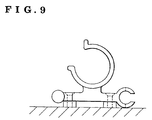
- Fig. 9 is a front view of a third embodiment of the hose holder of the present invention, illustrating the mounting holes provided in the base portion of the hose holder.
-
- Hereinbelow, the present invention will be described in detail with reference to the accompanying drawings.
- Fig. 1 shows a plastic holder 1 (hereinafter referred to as the hose holder) for detachably holding a hose 9 (shown in phantom lines in Fig. 3). The hose holder 1 is provided with a
base portion 2 and ahose holding portion 3 integrally formed with thebase portion 2. As shown in Fig. 1, thehose holding portion 3 of the hose holder 1 is formed in cross-section into a substantially C-clip shape having an upwardly orientedopening 4. As shown in Fig. 9, it is also possible for the hose holder 1 to have itsopening 4 upwardly and outwardly oriented. Thehose holding portion 3 of the hose holder 1 has a pair of opposite free ends which extend or flare outwardly to form a pair ofguide extensions 5. Theseguide extensions 5 function to guide the hose 9 into thehose holding portion 3 of the hose holder 1. Thehose holding portion 3 substantially corresponds in diameter to the hose 9. Consequently, it is preferable to provide a plurality of the hose holders 1, which vary in diameter of their hose holdingportions 3 to hold different-size or -diameter hoses 9 therein, as shown in Fig. 3. In case that the hose holder 1 is made of resilient materials such as resilient plastics and the like, since itshose holding portion 3 is resiliently deformed, it is possible for such resilient hose holder 1 to hold the different-diameter hoses 9, provided that theses hoses 9 vary in diameter within limits. - The
base portion 2 of the hose holder 1 has one of its opposite ends formed into a substantially C-clip shaped socket means, i.e., socket portion 6 having a horizontally oriented opening; and, the other of the opposite ends of thebase portion 2 formed into a plug means, i.e.,plug portion 7 which is so designed as to be detachably and rotatably mounted in the socket portion 6 of an adjacent one of thehose holders 3 in an insertion manner in a hose holder system of the present invention, the system being constructed of a plurality of the hose holders 1. As is clear from Fig. 3, in the hose holder system of the present invention, since it is necessary to have the different-size hose holders 1 detachably connected with each other, both the socket portions 6 and theplug portions 7 of such different-size hose holders 1 are so formed as to have the substantially same diameter. In assembly of the hose holder system of the present invention, theplug portion 7 of one of the hose holders 1 is inserted into the socket portion 6 of an adjacent one of the hose holders 1 from the side thereof. However, it is also possible to insert theplug portion 7 into the socket portion 6 from the right, as viewed in Fig. 1, provided that the hose holder 1 is made of resilient materials such as resilient plastics and the like. - As shown in Fig. 2, it is not necessary for the socket portion 6 of the hose holder 1 to extend over the entire width of the
base portion 2. In other words, the socket portion 6 may cut off itsintermediate portion 10, as shown in Fig. 2. A width t2 of such cut-offintermediate portion 10 of the socket portion 6 is slightly larger than a width tl of aneck portion 19 of theplug portion 7, which permits saidneck portion 19 to enter the cut-offintermediate portion 10 of the adjacent one of the hose holders 1 when theplug portion 7 of the hose holder 1 is rotated relative to the socket portion 6 of such adjacent one of the hose holders 1 in a condition in which the hose holder 1 has been connected with the adjacent one of the hose holders 1 in the hose holder system of the present invention. Incidentally, there is a fear that theplug portion 7 of the hose holder 1 drops sideward out of the socket portion 6 of the adjacent one of the hose holders 1 in the system due to vibration caused by instruments in operation. Consequently, in order to remove such fear, each of the socket portion 6 and theplug portion 7 is so designed as to have a sufficient width for preventing theplug portion 7 of the hose holder 1 from dropping sideward out of the socket portion 6 of the adjacent one of the hose holders 1. If necessary, amounting hole 8 is formed in the hose holder 1 so as to pass through an inner bottom surface of thehose holding portion 8 and thebase portion 2. Incidentally, in Fig. 9, themounting hole 8 is formed in each of opposite end portions of the base portion of the hose holder. When the hose holder 1 is provided with the mountinghole 8, it is possible to fixedly mount the hose holder 1 on the frames of the instruments, wall surface and the floor by means of screws, bolts and like fastening means. - In the hose holder system of the present invention, a desired number of the hose holders 1 are detachably connected with each other by detachably connecting each of their
plug portions 7 with the socket portion 6 of an adjacent one of the hose holders 1. As shown in Fig. 3, depending upon application, it is also possible to detachably connect a plurality of different-size hose holders 1 with each other, which holders 1 very in diameter of theirhose holding portions 3. The hose holders 1 thus connected with each other form one of desired constructions of the hose holder systems of the present invention. This hose holder system is disposed in a position in which the hoses 9 tend to be brought into contact with each other, and fixedly mounted therein, if necessary. Thereafter, the hoses 9 are detachably inserted into thehose holder portions 3 of the system from theopenings 4 thereof, so that the hoses 9 are spaced apart from each other in neat, orderly arrangements to prevent them from interfering with each other. - Figs. 4(A), 4(B), 4(C), 4(D), 4(E) and 4(F) show various constructions of the hose holder system of the present invention, in which a plurality of the hose holders 1 are detachably connected with each other to form various types of annular constructions. In each of such annular constructions: the
plug portion 7 of the hose holder 1 is detachably and rotatably mounted in the socket portion 6 of an adjacent one of the hose holders 1 in an insertion manner; and, the width t1 of the neck portion 9 of theplug portion 7 of the hose holder 1 is smaller than the width t2 of the cut-offintermediate portion 10 of the socket portion 6 of the adjacent one of the hose holders 1. Of the annular constructions: ones shown in Figs. 4(A), 4(B) and 4(C) enable the hose holder system of the present invention to encircle tubular objects, rod-like objects, rod-like frames and the like; and, ones shown in Figs. 4(D) and 4(E) enable the hose holder system of the present invention to encircle plate-like frames and the like. - Figs. 5 to 8 show a
hose holder 11 of a second embodiment of the present invention. Thehose holder 11 is fixedly mounted on the instruments, wall surfaces, floor and the like through itssupport rail 12. As shown in Fig. 7, thesupport rail 12 is constructed of: abottom plate 13 fixedly mounted on the instruments and the like; and, a pair ofsupport walls 14 extending upward from opposite sides of thebottom plate 13. Each of thesupport walls 14 is provided with a longitudinalinner support grooves 15. - On the other hand, the
hose holder 11 has the same construction as that of the hose holder 1, except that thehose holder 11 is provided with a pair ofhorizontal projections 16 in opposite sides of thehose holding portion 2, as viewed in Fig. 7. Theseprojections 16 of thehose holder 11 are slidably inserted into a pair ofsupport grooves 15 of thesupport rail 12 from the end of therails 12, so that a plurality of thehose holders 11 are supported by thesame support rail 12, as shown in Fig. 8. - Preferably, a stopper 17 is fixedly mounted in the
support rail 12 so as to prevent thehose holders 11 from slidably moving along thesupport rail 12. The stopper 17 is provided with a pair ofleg portions 18 which engage with thesupport grooves 15 of thesupport rail 12 in the substantially same manner as that of theprojections 16 of thehose holder 11. Namely, theleg portions 18 of the stopper 17 are slidably inserted into thesupport grooves 15 of thesupport rail 12 from the end of therail 12 and fixedly mounted therein.
Claims (6)
- A hose holder system comprising at least a pair of hose holders (1) provided each with a base portion (2) and a hose holding portion (3) for holding a hose (9) therein, wherein said hose holding portion (3) is integrally formed with said base portion (2) and provided with an opening (4) for receiving said hose therein ; and
said base portion (2) has one (6) of its opposite end portions formed into a socket means and the other of said opposite end portions formed into a plug means (7) sized to be fitted in said socket means (6),
characterized in that:said plug means (7) of said hose holder is provided with a neck portion (19) through which said plug means (7) is integrally connected with said base portion (2) ;said socket means (6) is provided with a cut-off intermediate portion (10) which is larger in width than said neck portion (19) ; andsaid plug means (7) of one of said hose holders is rotatably mounted in said socket means (6) of the other of said hose holders. - The hose holder system, as set forth in claim 1, wherein :
said hose holders (1) are different in diameter of said hose holding portion (3) from each other, while connected with each other. - The hose holder system, as set forth in claim 1 or 2, wherein :
said hose holders (1) are linearly connected with each other. - The hose holder system, as set forth in claim 1 or 2, wherein :
said holse holders (1) are connected with each other to form an annular construction of the hose holder system. - The hose holder system, as set forth in any one of claims 1 to 4, wherein :
said hose holder (1) is provided with a through-hole (8) passing through an inner wall surface of said hose holding portion (3) and said base portion (2), said though-hole (8) serving as a mounting hole of said hose holder. - The hose holder system, as set forth in any one of claims 1 to 5, wherein :said hose holder (1) is provided with a pair of projections (16) in opposite sides of said base portion (2) ; andsaid projections (16) engage with a support rail (12) fixed to instruments, wall surfaces and like supports.
Applications Claiming Priority (3)
| Application Number | Priority Date | Filing Date | Title |
|---|---|---|---|
| JP18407196 | 1996-06-25 | ||
| JP18407196 | 1996-06-25 | ||
| JP184071/96 | 1996-06-25 |
Publications (2)
| Publication Number | Publication Date |
|---|---|
| EP0816735A1 EP0816735A1 (en) | 1998-01-07 |
| EP0816735B1 true EP0816735B1 (en) | 2001-04-11 |
Family
ID=16146879
Family Applications (1)
| Application Number | Title | Priority Date | Filing Date |
|---|---|---|---|
| EP96402192A Expired - Lifetime EP0816735B1 (en) | 1996-06-25 | 1996-10-15 | Hose holder system |
Country Status (3)
| Country | Link |
|---|---|
| US (1) | US6109569A (en) |
| EP (1) | EP0816735B1 (en) |
| DE (1) | DE69612488T2 (en) |
Families Citing this family (108)
| Publication number | Priority date | Publication date | Assignee | Title |
|---|---|---|---|---|
| FR2798719B1 (en) * | 1999-09-17 | 2001-11-23 | Plastub | ASSEMBLY PROFILE |
| US6370740B1 (en) * | 2000-06-16 | 2002-04-16 | The United States Of America As Represented By The Secretary Of The Navy | Mechanical clamp for cylindrical objects |
| US6328459B1 (en) * | 2000-08-18 | 2001-12-11 | Adams Mfg. Corp. | Releasable holder |
| EP1209397A1 (en) * | 2000-11-23 | 2002-05-29 | Adam Gerich | Holding device for tubular articles |
| US6367118B1 (en) * | 2000-12-08 | 2002-04-09 | Shop Vac Corporation | Vacuum cleaner hose clip |
| GB0101202D0 (en) * | 2001-01-17 | 2001-02-28 | Smiths Group Plc | Mounts |
| US20030036297A1 (en) * | 2001-08-01 | 2003-02-20 | Kilkenny Stephen W. | Snap-in assembly for multiple high current conductive lines |
| US6531829B1 (en) * | 2002-01-31 | 2003-03-11 | Chin-Sung Tsai | Connector of a decorative lighting string |
| US7490727B2 (en) * | 2002-12-23 | 2009-02-17 | Spiers Dennis D | Storage rack |
| DE20301511U1 (en) * | 2003-01-31 | 2004-06-09 | Veritas Ag | Holding device in particular suitable for joining vehicle component to pipe, designed in pipe enveloping ring shape |
| US20040182972A1 (en) * | 2003-03-19 | 2004-09-23 | Bakos Gregory J. | Electrical connector holder |
| WO2004114361A2 (en) * | 2003-06-25 | 2004-12-29 | Koninklijke Philips Electronics N.V. | Stabilizing device, fluorescent lamp comprising such a device, and method of reinforcing a fluorescent lamp |
| US7131170B2 (en) * | 2003-06-27 | 2006-11-07 | Quickie Manufacturing Corporation | Threaded push broom locking clip |
| US20080182679A1 (en) * | 2004-06-24 | 2008-07-31 | Larry Trudeau | Golf ball retrieving system |
| US7185770B1 (en) * | 2005-03-22 | 2007-03-06 | Roten Randal E | Modular storage rack |
| US7213307B2 (en) * | 2005-05-19 | 2007-05-08 | Ergodyne Corporation | Clip |
| US7608782B2 (en) * | 2005-06-09 | 2009-10-27 | Hill Douglas C | Clip |
| US7456361B2 (en) * | 2005-06-09 | 2008-11-25 | Hill Douglas C | Clip for flexible armored cable |
| DE202005011490U1 (en) * | 2005-07-21 | 2006-12-14 | Weidmüller Interface GmbH & Co. KG | Electrical conductor e.g. flat cable conductor, fastener, has strip with openings and retainers, where fastener is arranged on strip and retaining section, on which electrical conductors are supported at distance from each other |
| TW200720762A (en) * | 2005-10-20 | 2007-06-01 | Samsung Electronics Co Ltd | Backlight assembly and display device having the same |
| KR101245113B1 (en) * | 2005-12-15 | 2013-03-25 | 삼성디스플레이 주식회사 | Lamp fixing member, back light assembly and liquid crystal display apparatus having the same |
| US7537115B2 (en) * | 2006-02-03 | 2009-05-26 | Quickie Manufacturing Corporation | Display apparatus for implements with handles and working ends |
| US7520478B2 (en) * | 2006-03-06 | 2009-04-21 | Whitfield Mariel G | Hose attachment for securing a hose adjacent a shampoo bowl |
| SE530259C2 (en) * | 2006-10-20 | 2008-04-15 | Cargotec Patenter Ab | A system for attaching pipes to a supporting structural element, which system includes fastening modules |
| US8091184B2 (en) * | 2007-04-19 | 2012-01-10 | Hope Global, Division Of Nfa Corp. | Festooned trim clip system and method for attaching festooned clips to a substrate |
| US8099837B2 (en) * | 2007-09-07 | 2012-01-24 | Hope Global, Division Of Nfa Corporation | Low-profile upholstery clip for attaching a bead to a foam substrate |
| GB2455739A (en) * | 2007-12-19 | 2009-06-24 | Vax Ltd | Suction hose arrangement for vacuum cleaners |
| US8020259B2 (en) * | 2008-06-02 | 2011-09-20 | Cyber Power Systems Inc. | Cable clamp and cable clamp assembly |
| US8266747B1 (en) | 2008-06-24 | 2012-09-18 | Nomaco Inc. | Mattress side/edge support system |
| ATE548297T1 (en) * | 2008-06-30 | 2012-03-15 | Ferrinox Automotive Sro | STACKING COLUMN |
| DE102008055823A1 (en) * | 2008-11-04 | 2010-05-06 | Mulzer, Stephan, Dr. | holder |
| US8561236B2 (en) | 2009-06-22 | 2013-10-22 | Nomaco Inc. | Stepped-edge and side-support members, assemblies, systems, and related methods, particularly for bedding and seating |
| DE202009011160U1 (en) * | 2009-08-18 | 2010-10-21 | Hellermann Tyton Gmbh | Basic element and web element for the modular formation of a ring body and such |
| CN102510729B (en) * | 2009-08-21 | 2014-10-01 | 尼古拉斯·帕里 | Walking stick |
| US8646136B2 (en) * | 2009-08-27 | 2014-02-11 | Nomaco Inc. | Assemblies, systems, and related methods employing interlocking components to provide at least a portion of an encasement, particularly for bedding and seating applications |
| US8375493B2 (en) | 2009-08-27 | 2013-02-19 | Sealy Technology Llc | One piece foam mattress core encasement |
| US20120068027A1 (en) * | 2009-12-30 | 2012-03-22 | Cnd Products Llc | Device for holding packages |
| US20110179579A1 (en) * | 2010-01-27 | 2011-07-28 | Nomaco Inc. | Expandable edge-support members, assemblies, and related methods, suitable for bedding and seating applications and innersprings |
| EP2366927A1 (en) * | 2010-03-15 | 2011-09-21 | Fresenius Kabi Deutschland GmbH | Clamp and clamp system and use of same |
| USD677097S1 (en) | 2010-05-06 | 2013-03-05 | Nomaco, Inc. | Slotted side support |
| USD695550S1 (en) * | 2010-08-17 | 2013-12-17 | Nomaca Inc. | Side support |
| USD694042S1 (en) * | 2010-08-17 | 2013-11-26 | Nomaco Inc. | Side support |
| USD694554S1 (en) * | 2010-08-17 | 2013-12-03 | Nomaco Inc. | Side support |
| USD692689S1 (en) * | 2010-08-17 | 2013-11-05 | Nomaco Inc. | Side support |
| US8632037B1 (en) | 2011-04-11 | 2014-01-21 | Koreann H. Rael | Hose holder |
| US20120285740A1 (en) * | 2011-05-10 | 2012-11-15 | Tyco Electronics Corporation | Cable assembly |
| US8631964B1 (en) | 2011-05-10 | 2014-01-21 | Koreann H. Rael | Hose holding container assembly |
| USD673801S1 (en) | 2011-08-03 | 2013-01-08 | Nomaco Inc. | Mattress bed encasement |
| USD673800S1 (en) | 2011-08-03 | 2013-01-08 | Nomaco Inc. | Mattress bed encasement |
| US8485690B1 (en) * | 2011-09-08 | 2013-07-16 | Virginia Garcia | Decorative light string clip device |
| USD675051S1 (en) | 2011-09-30 | 2013-01-29 | Nomaco Inc. | Edge support cushion |
| US20130233597A1 (en) * | 2012-03-12 | 2013-09-12 | Robert R. Suiter | Wiring dressing rings |
| CA2770929C (en) | 2012-03-12 | 2014-06-17 | Steven Robert Schiller | Combined protector and hose support device for containment berm |
| US9337636B2 (en) * | 2012-06-19 | 2016-05-10 | Frank Notaro | Modular fastening system |
| US20130334374A1 (en) * | 2012-06-19 | 2013-12-19 | Frank Notaro | Modular Fastening System |
| CN103580503A (en) * | 2012-08-07 | 2014-02-12 | 江苏固德威电源科技有限公司 | Novel wiring harness fixing processing bayonet of photovoltaic inverter |
| US20140259620A1 (en) * | 2013-03-13 | 2014-09-18 | Thaddeus R. Hicks | Hose retention system |
| USD737074S1 (en) | 2013-07-03 | 2015-08-25 | Nomaco Inc. | Foam cushion base |
| USD740053S1 (en) | 2013-07-03 | 2015-10-06 | Nomaco Inc. | Foam cushion base |
| EP3033123B1 (en) | 2013-08-12 | 2018-10-03 | Somnus Medical, LLC | Iv set system with coded components |
| US11058813B2 (en) | 2013-08-12 | 2021-07-13 | Somnus Medical, LLC | IV extension set or IV set system with bypass manifold |
| US20150068941A1 (en) | 2013-09-10 | 2015-03-12 | Angiodynamics, Inc. | Containment Clip for Medical Devices |
| US20150115111A1 (en) * | 2013-10-28 | 2015-04-30 | Tim Smith | Hose Support Device |
| HK1188535A2 (en) * | 2014-01-14 | 2014-05-02 | Talent Key Holdings Ltd | A screwdriver bit, a screwdriver bit connecting device and a screwdriver bits set |
| US9829120B1 (en) * | 2014-08-20 | 2017-11-28 | VCE IP Holding Company LLC | Cable management clip assemblies, systems, and methods |
| USD761644S1 (en) | 2014-10-24 | 2016-07-19 | Tectran Mfg. Inc. | Four hole clamp |
| USD737081S1 (en) | 2014-10-24 | 2015-08-25 | Apple Inc. | Display stand |
| USD761643S1 (en) | 2014-10-24 | 2016-07-19 | Tectran Mfg. Inc. | Two hole clamp |
| CN104606736B (en) * | 2015-02-15 | 2018-01-19 | 天津市第五中心医院 | A kind of movable fixture being connected for transfusion device with Infusion support |
| US9920858B2 (en) | 2015-06-30 | 2018-03-20 | Cnh Industrial America Llc | Mounting device for tubular elements |
| CN104984430A (en) * | 2015-07-06 | 2015-10-21 | 昆山韦睿医疗科技有限公司 | Fluid pipe set for peritoneal dialysis |
| CN104984428A (en) * | 2015-07-06 | 2015-10-21 | 昆山韦睿医疗科技有限公司 | Fluid pipe clamp and attached pipe clamp for peritoneal dialysis |
| USD794439S1 (en) | 2015-07-16 | 2017-08-15 | Tectran Mfg. Inc. | Single hole clamp |
| US9834431B2 (en) | 2015-08-28 | 2017-12-05 | Hope Global, Division Of Nfa Corp. | Listing bead for upholstery clips |
| US20170128663A1 (en) * | 2015-11-05 | 2017-05-11 | Somnus Medical, LLC | IV Set and IV Set System Management |
| CN105485097A (en) * | 2015-12-31 | 2016-04-13 | 天津罗斯诺普信息技术有限公司 | Rotary knob fastening device |
| DE102016110781B4 (en) * | 2016-06-13 | 2022-09-01 | Lisa Dräxlmaier GmbH | Device and method for intermediate storage of cables |
| USD795051S1 (en) * | 2016-07-19 | 2017-08-22 | Tectran Mfg. Inc. | Four hole swivel clamp |
| USD799953S1 (en) * | 2016-07-19 | 2017-10-17 | Tectran Mfg. Inc. | Two hole swivel clamp |
| USD795052S1 (en) * | 2016-08-08 | 2017-08-22 | Tectran Mfg. Inc. | Three hole swivel clamp |
| US20180058610A1 (en) * | 2016-08-31 | 2018-03-01 | Broken W Enterprises LLC | Tubular Securing Device |
| USD809194S1 (en) * | 2016-10-21 | 2018-01-30 | Craig Falcone | Smoking accessory |
| USD822476S1 (en) | 2016-10-26 | 2018-07-10 | Hellermanntyton Corporation | Multiple option clip |
| US20180236653A1 (en) * | 2017-02-22 | 2018-08-23 | Jui-Chien Kao | Tool clamping assembly |
| JP6743734B2 (en) * | 2017-03-16 | 2020-08-19 | 株式会社オートネットワーク技術研究所 | Shape maintenance tool |
| US10883637B2 (en) | 2017-04-19 | 2021-01-05 | Rene Ricardo ENDARA | Device for reel-less spooling of hoses, flexible pipes and cables |
| US11103989B2 (en) | 2017-06-14 | 2021-08-31 | Jonathan Hurley | Interchangeable and interconnectable tool organizing device |
| US20180361563A1 (en) * | 2017-06-14 | 2018-12-20 | Jonathan Hurley | The tool box widget |
| CN107264437A (en) * | 2017-06-19 | 2017-10-20 | 芜湖侨云友星电气工业有限公司 | A kind of automobile chassis pipe harness fixing rack |
| EP3701179B1 (en) * | 2017-10-25 | 2024-04-24 | Teck Keung Industrial Limited | Line organizer |
| DE102018108805A1 (en) | 2018-04-13 | 2019-10-17 | Dr. Ing. H.C. F. Porsche Aktiengesellschaft | Air guide arrangement for a motor vehicle |
| USD876432S1 (en) | 2018-04-26 | 2020-02-25 | Hewlett Packard Enterprise Development Lp | Enclosure |
| US10939716B1 (en) * | 2018-07-03 | 2021-03-09 | Daniel Toro | Adjustable hat member |
| US10439381B1 (en) * | 2018-07-10 | 2019-10-08 | The Boeing Company | Electrical raceway system and associated wire bundle clamp system and method |
| USD939510S1 (en) | 2018-09-07 | 2021-12-28 | Hewlett Packard Enterprise Development Lp | Enclosure |
| US11202386B2 (en) | 2018-09-28 | 2021-12-14 | Hewlett Packard Enterprise Development Lp | Modular cable management system |
| FR3088943B1 (en) * | 2018-11-28 | 2021-12-17 | Soletanche Freyssinet | HYDRAULIC VALVE EQUIPPED WITH SNAP LINKS |
| DE102019101936A1 (en) * | 2019-01-25 | 2020-07-30 | Ebm-Papst Mulfingen Gmbh & Co. Kg | Cable magazine |
| US10676047B1 (en) * | 2019-03-15 | 2020-06-09 | Denso International America, Inc. | Wire harness mounting assembly |
| US11549616B2 (en) * | 2019-03-18 | 2023-01-10 | Draegerwerk Ag & Co. Kgaa | Cable management system and cable holder |
| GB2583517A (en) * | 2019-05-02 | 2020-11-04 | Keymed Medical & Industrial Equipment Ltd | Holder for medical instrument |
| USD893926S1 (en) | 2019-06-21 | 2020-08-25 | Apple Inc. | Product retainer |
| US11662041B2 (en) | 2019-07-29 | 2023-05-30 | Erico International Corporation | Support clip |
| US11707832B2 (en) * | 2020-12-07 | 2023-07-25 | Jonathan Hurley | Tool organizer |
| EP4036447B1 (en) | 2021-01-28 | 2024-01-24 | SOMA GmbH & Co. KG | Pipe fastener |
| US11938613B2 (en) * | 2021-04-30 | 2024-03-26 | Jonathan Hurley | Modular magnetic support strip |
| EP4275847A1 (en) * | 2022-05-13 | 2023-11-15 | Techtronic Cordless GP | Rail storage system with end caps |
| DE102022125557B3 (en) * | 2022-10-04 | 2023-12-21 | Accuride International Gmbh | Clip |
Family Cites Families (11)
| Publication number | Priority date | Publication date | Assignee | Title |
|---|---|---|---|---|
| US1906874A (en) * | 1931-12-26 | 1933-05-02 | Arthur I Platt | Implement holder |
| DE699892C (en) * | 1939-03-07 | 1942-08-07 | Siemens Schuckertwerke Akt Ges | Row clamp composed of individual bodies |
| US3313009A (en) * | 1965-03-12 | 1967-04-11 | Beckson Mfg Inc | Spring clip |
| DE2619702C2 (en) * | 1976-05-04 | 1984-07-26 | Hilti Ag, Schaan | Clamp for holding pipes, cables and the like. |
| DE2624333C2 (en) * | 1976-05-31 | 1984-07-05 | Hilti Ag, Schaan | clamp |
| US4306697A (en) * | 1980-06-16 | 1981-12-22 | Mathews Lyle H | Conduit spacer system |
| DE3207891A1 (en) * | 1982-03-05 | 1983-09-15 | Fischer, Artur, Dr.H.C., 7244 Waldachtal | PLASTIC TUBE CLAMP |
| US4804020A (en) * | 1987-05-27 | 1989-02-14 | Proprietary Technology, Inc. | Conduit liner assembly and method for installation |
| EP0428896B1 (en) * | 1989-11-24 | 1993-01-20 | Hydac Technology Gmbh | Fastening system |
| US4999885A (en) * | 1990-03-01 | 1991-03-19 | Lee Michael D | Device for maintaining orderly tubing or wiring |
| DE9201892U1 (en) * | 1992-02-14 | 1992-04-02 | Hermann Kleinhuis Gmbh & Co Kg, 5880 Luedenscheid, De |
-
1996
- 1996-10-15 DE DE69612488T patent/DE69612488T2/en not_active Expired - Fee Related
- 1996-10-15 EP EP96402192A patent/EP0816735B1/en not_active Expired - Lifetime
- 1996-10-22 US US08/734,875 patent/US6109569A/en not_active Expired - Fee Related
Also Published As
| Publication number | Publication date |
|---|---|
| US6109569A (en) | 2000-08-29 |
| DE69612488T2 (en) | 2001-11-29 |
| DE69612488D1 (en) | 2001-05-17 |
| EP0816735A1 (en) | 1998-01-07 |
Similar Documents
| Publication | Publication Date | Title |
|---|---|---|
| EP0816735B1 (en) | Hose holder system | |
| US7520476B2 (en) | Cable support system | |
| US7294789B1 (en) | Retainer with band clip and cable holder | |
| US20040065459A1 (en) | Protection member for a mesh cable tray, and a tray including said member | |
| US6883762B2 (en) | Clamp | |
| US5399812A (en) | Housing for supporting and routing cables | |
| US6585196B2 (en) | Fastener for pipe or the like | |
| US9939601B2 (en) | Anchoring cables to rack with self-locking cable clamp arrangements | |
| US20050092509A1 (en) | Gangable electrical box | |
| CN1194734A (en) | Cable management encloure | |
| US20010030052A1 (en) | Raceway fitting with or without fitting base | |
| US6424779B1 (en) | Fiber trough coupling system | |
| US6249635B1 (en) | Universal fiber optic splice holder | |
| JP2004044698A (en) | Clamp for long article | |
| US20140357095A1 (en) | Block connector holder | |
| US5615852A (en) | Cable clip | |
| US11258240B1 (en) | Cable guides for use with cable trays | |
| US6472596B1 (en) | Coupling mechanism for an electrical fitting including energy absorbing self-returning snaps | |
| JP2891408B2 (en) | Hose holder | |
| JP2008154343A (en) | Holder for holding corrugated tube | |
| US7207432B2 (en) | Linear motion drive system and rail holder | |
| US6231014B1 (en) | Mechanism for low profile enclosures | |
| US5261827A (en) | Movable shroud center standoff | |
| WO1997044860A1 (en) | Wire manager clip | |
| GB2482189A (en) | Cable mounting clip |
Legal Events
| Date | Code | Title | Description |
|---|---|---|---|
| PUAI | Public reference made under article 153(3) epc to a published international application that has entered the european phase |
Free format text: ORIGINAL CODE: 0009012 |
|
| AK | Designated contracting states |
Kind code of ref document: A1 Designated state(s): BE CH DE ES FR GB IT LI NL SE |
|
| 17P | Request for examination filed |
Effective date: 19980519 |
|
| 17Q | First examination report despatched |
Effective date: 19990604 |
|
| GRAG | Despatch of communication of intention to grant |
Free format text: ORIGINAL CODE: EPIDOS AGRA |
|
| GRAG | Despatch of communication of intention to grant |
Free format text: ORIGINAL CODE: EPIDOS AGRA |
|
| GRAH | Despatch of communication of intention to grant a patent |
Free format text: ORIGINAL CODE: EPIDOS IGRA |
|
| GRAH | Despatch of communication of intention to grant a patent |
Free format text: ORIGINAL CODE: EPIDOS IGRA |
|
| GRAA | (expected) grant |
Free format text: ORIGINAL CODE: 0009210 |
|
| AK | Designated contracting states |
Kind code of ref document: B1 Designated state(s): BE CH DE ES FR GB IT LI NL SE |
|
| PG25 | Lapsed in a contracting state [announced via postgrant information from national office to epo] |
Ref country code: NL Free format text: LAPSE BECAUSE OF FAILURE TO SUBMIT A TRANSLATION OF THE DESCRIPTION OR TO PAY THE FEE WITHIN THE PRESCRIBED TIME-LIMIT Effective date: 20010411 Ref country code: LI Free format text: LAPSE BECAUSE OF FAILURE TO SUBMIT A TRANSLATION OF THE DESCRIPTION OR TO PAY THE FEE WITHIN THE PRESCRIBED TIME-LIMIT Effective date: 20010411 Ref country code: IT Free format text: LAPSE BECAUSE OF FAILURE TO SUBMIT A TRANSLATION OF THE DESCRIPTION OR TO PAY THE FEE WITHIN THE PRE;WARNING: LAPSES OF ITALIAN PATENTS WITH EFFECTIVE DATE BEFORE 2007 MAY HAVE OCCURRED AT ANY TIME BEFORE 2007. THE CORRECT EFFECTIVE DATE MAY BE DIFFERENT FROM THE ONE RECORDED.SCRIBED TIME-LIMIT Effective date: 20010411 Ref country code: CH Free format text: LAPSE BECAUSE OF FAILURE TO SUBMIT A TRANSLATION OF THE DESCRIPTION OR TO PAY THE FEE WITHIN THE PRESCRIBED TIME-LIMIT Effective date: 20010411 Ref country code: BE Free format text: LAPSE BECAUSE OF FAILURE TO SUBMIT A TRANSLATION OF THE DESCRIPTION OR TO PAY THE FEE WITHIN THE PRESCRIBED TIME-LIMIT Effective date: 20010411 |
|
| REG | Reference to a national code |
Ref country code: CH Ref legal event code: EP |
|
| ET | Fr: translation filed | ||
| REF | Corresponds to: |
Ref document number: 69612488 Country of ref document: DE Date of ref document: 20010517 |
|
| PG25 | Lapsed in a contracting state [announced via postgrant information from national office to epo] |
Ref country code: SE Free format text: LAPSE BECAUSE OF FAILURE TO SUBMIT A TRANSLATION OF THE DESCRIPTION OR TO PAY THE FEE WITHIN THE PRESCRIBED TIME-LIMIT Effective date: 20010711 |
|
| NLV1 | Nl: lapsed or annulled due to failure to fulfill the requirements of art. 29p and 29m of the patents act | ||
| REG | Reference to a national code |
Ref country code: CH Ref legal event code: PL |
|
| PG25 | Lapsed in a contracting state [announced via postgrant information from national office to epo] |
Ref country code: ES Free format text: LAPSE BECAUSE OF FAILURE TO SUBMIT A TRANSLATION OF THE DESCRIPTION OR TO PAY THE FEE WITHIN THE PRESCRIBED TIME-LIMIT Effective date: 20011030 |
|
| REG | Reference to a national code |
Ref country code: GB Ref legal event code: IF02 |
|
| PLBE | No opposition filed within time limit |
Free format text: ORIGINAL CODE: 0009261 |
|
| STAA | Information on the status of an ep patent application or granted ep patent |
Free format text: STATUS: NO OPPOSITION FILED WITHIN TIME LIMIT |
|
| 26N | No opposition filed | ||
| PGFP | Annual fee paid to national office [announced via postgrant information from national office to epo] |
Ref country code: GB Payment date: 20080801 Year of fee payment: 13 |
|
| PGFP | Annual fee paid to national office [announced via postgrant information from national office to epo] |
Ref country code: DE Payment date: 20081103 Year of fee payment: 13 |
|
| PGFP | Annual fee paid to national office [announced via postgrant information from national office to epo] |
Ref country code: FR Payment date: 20081016 Year of fee payment: 13 |
|
| REG | Reference to a national code |
Ref country code: FR Ref legal event code: ST Effective date: 20100630 |
|
| PG25 | Lapsed in a contracting state [announced via postgrant information from national office to epo] |
Ref country code: FR Free format text: LAPSE BECAUSE OF NON-PAYMENT OF DUE FEES Effective date: 20091102 Ref country code: DE Free format text: LAPSE BECAUSE OF NON-PAYMENT OF DUE FEES Effective date: 20100501 |
|
| PG25 | Lapsed in a contracting state [announced via postgrant information from national office to epo] |
Ref country code: GB Free format text: LAPSE BECAUSE OF NON-PAYMENT OF DUE FEES Effective date: 20091015 |