EP0816697B1 - Hydrostatisches Lager für hydraulische Maschinen von hydroelektrischen Einheiten - Google Patents
Hydrostatisches Lager für hydraulische Maschinen von hydroelektrischen Einheiten Download PDFInfo
- Publication number
- EP0816697B1 EP0816697B1 EP97201910A EP97201910A EP0816697B1 EP 0816697 B1 EP0816697 B1 EP 0816697B1 EP 97201910 A EP97201910 A EP 97201910A EP 97201910 A EP97201910 A EP 97201910A EP 0816697 B1 EP0816697 B1 EP 0816697B1
- Authority
- EP
- European Patent Office
- Prior art keywords
- bearing
- hydrostatic
- sets
- support chambers
- chambers
- Prior art date
- Legal status (The legal status is an assumption and is not a legal conclusion. Google has not performed a legal analysis and makes no representation as to the accuracy of the status listed.)
- Expired - Lifetime
Links
- 230000002706 hydrostatic effect Effects 0.000 title claims abstract description 48
- 239000000314 lubricant Substances 0.000 claims abstract description 20
- 239000012530 fluid Substances 0.000 claims abstract description 17
- 238000001914 filtration Methods 0.000 claims abstract description 8
- 238000000746 purification Methods 0.000 claims abstract description 8
- XLYOFNOQVPJJNP-UHFFFAOYSA-N water Substances O XLYOFNOQVPJJNP-UHFFFAOYSA-N 0.000 claims abstract description 6
- 230000000694 effects Effects 0.000 description 2
- 230000002950 deficient Effects 0.000 description 1
- 230000006866 deterioration Effects 0.000 description 1
- 230000002349 favourable effect Effects 0.000 description 1
- 238000002347 injection Methods 0.000 description 1
- 239000007924 injection Substances 0.000 description 1
- 238000012423 maintenance Methods 0.000 description 1
- 230000010349 pulsation Effects 0.000 description 1
- 239000007787 solid Substances 0.000 description 1
- 230000001052 transient effect Effects 0.000 description 1
Images


Classifications
-
- F—MECHANICAL ENGINEERING; LIGHTING; HEATING; WEAPONS; BLASTING
- F16—ENGINEERING ELEMENTS AND UNITS; GENERAL MEASURES FOR PRODUCING AND MAINTAINING EFFECTIVE FUNCTIONING OF MACHINES OR INSTALLATIONS; THERMAL INSULATION IN GENERAL
- F16C—SHAFTS; FLEXIBLE SHAFTS; ELEMENTS OR CRANKSHAFT MECHANISMS; ROTARY BODIES OTHER THAN GEARING ELEMENTS; BEARINGS
- F16C32/00—Bearings not otherwise provided for
- F16C32/06—Bearings not otherwise provided for with moving member supported by a fluid cushion formed, at least to a large extent, otherwise than by movement of the shaft, e.g. hydrostatic air-cushion bearings
- F16C32/0629—Bearings not otherwise provided for with moving member supported by a fluid cushion formed, at least to a large extent, otherwise than by movement of the shaft, e.g. hydrostatic air-cushion bearings supported by a liquid cushion, e.g. oil cushion
- F16C32/064—Bearings not otherwise provided for with moving member supported by a fluid cushion formed, at least to a large extent, otherwise than by movement of the shaft, e.g. hydrostatic air-cushion bearings supported by a liquid cushion, e.g. oil cushion the liquid being supplied under pressure
- F16C32/0644—Details of devices to control the supply of liquids to the bearings
-
- F—MECHANICAL ENGINEERING; LIGHTING; HEATING; WEAPONS; BLASTING
- F16—ENGINEERING ELEMENTS AND UNITS; GENERAL MEASURES FOR PRODUCING AND MAINTAINING EFFECTIVE FUNCTIONING OF MACHINES OR INSTALLATIONS; THERMAL INSULATION IN GENERAL
- F16C—SHAFTS; FLEXIBLE SHAFTS; ELEMENTS OR CRANKSHAFT MECHANISMS; ROTARY BODIES OTHER THAN GEARING ELEMENTS; BEARINGS
- F16C32/00—Bearings not otherwise provided for
- F16C32/06—Bearings not otherwise provided for with moving member supported by a fluid cushion formed, at least to a large extent, otherwise than by movement of the shaft, e.g. hydrostatic air-cushion bearings
- F16C32/0629—Bearings not otherwise provided for with moving member supported by a fluid cushion formed, at least to a large extent, otherwise than by movement of the shaft, e.g. hydrostatic air-cushion bearings supported by a liquid cushion, e.g. oil cushion
- F16C32/064—Bearings not otherwise provided for with moving member supported by a fluid cushion formed, at least to a large extent, otherwise than by movement of the shaft, e.g. hydrostatic air-cushion bearings supported by a liquid cushion, e.g. oil cushion the liquid being supplied under pressure
- F16C32/0651—Details of the bearing area per se
- F16C32/0659—Details of the bearing area per se of pockets or grooves
-
- F—MECHANICAL ENGINEERING; LIGHTING; HEATING; WEAPONS; BLASTING
- F16—ENGINEERING ELEMENTS AND UNITS; GENERAL MEASURES FOR PRODUCING AND MAINTAINING EFFECTIVE FUNCTIONING OF MACHINES OR INSTALLATIONS; THERMAL INSULATION IN GENERAL
- F16C—SHAFTS; FLEXIBLE SHAFTS; ELEMENTS OR CRANKSHAFT MECHANISMS; ROTARY BODIES OTHER THAN GEARING ELEMENTS; BEARINGS
- F16C32/00—Bearings not otherwise provided for
- F16C32/06—Bearings not otherwise provided for with moving member supported by a fluid cushion formed, at least to a large extent, otherwise than by movement of the shaft, e.g. hydrostatic air-cushion bearings
- F16C32/0681—Construction or mounting aspects of hydrostatic bearings, for exclusively rotary movement, related to the direction of load
- F16C32/0692—Construction or mounting aspects of hydrostatic bearings, for exclusively rotary movement, related to the direction of load for axial load only
Definitions
- This invention relates to a hydrostatic bearing particularly for hydraulic machines of hydroelectric units.
- the object of the present invention is to obviate the aforesaid drawback by providing a hydrostatic bearing able to also operate under emergency conditions, so reducing any damage to a minimum.
- the bearing of the invention achieves the stated object in that if one of the purification and/or filtration plants is faulty, the remaining purification and/or filtration plants can continue to supply the pressurized lubricant (water) for at least the time required for halting the hydroelectric unit, each set of hydrostatic support chambers being moreover dimensioned to be able to alone support the operating loads of the unit.
- each bearing is as if it were formed from at least two redundant twin bearings, each of which is able to permit operation of the bearing, with the necessary minimum margin to ensure its integrity during the unit stoppage transient.
- the bearing is divisible into two portions containing a set of support pockets. Said portions are functionally identical and can always operate simultaneously. As each of the two portions ensures operation with a sufficient margin of safety, it is apparent that during normal operation with both systems operative, the bearing operates under more favourable conditions and hence with a greater safety margin towards all problems connected with possible sudden accidental load variations due to hydraulic thrust pulsation and towards possible problems of mechanical origin such as expansion etc.
- Each bearing portion housing one of the sets of support pockets is redundant but is not a passive element during normal operation.
- the two bearing portions housing the sets of support pockets are totally independent and hence are redundant both with regard to fluid feed and with regard to the active support part.
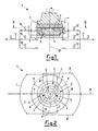
- Figure 1 is an elevational section through a first embodiment of a hydrostatic bearing of the invention, installed in a hydroelectric unit which is only partly visible.
- Figure 2 is a section on the line II-II of Figure 1.
- Figure 3 is an elevational section through a second embodiment of a hydrostatic bearing of the invention, installed in a hydroelectric unit which is only partly visible.
- Figure 4 is a section on the line IV-IV of Figure 3.
- Figure 5 is an elevational section through a hydrostatic bearing which is not an embodiment of the invention, installed in a hydroelectric unit which is only partly visible, whereby the chambers alternate as in US 3 501 205 A.
- Figure 6 is a section on the line VI-VI of Figure 5.
- the hydrostatic bearing is applicable in particular to hydraulic machines of hydroelectric units. It comprises a first bearing element 2 and a second bearing element 3 which can move relative to each other and between which there can be interposed a film (not visible in the figures) of lubricant fluid which in the illustrated embodiment is water drawn from a penstock at a pressure sufficient to space the first element 2 from the second element 3.
- One of said bearing elements preferably the second 3, which is the lower
- the support chambers 4 are grouped to form at least one first set 5 and at least one second set 6 of concentric hydrostatic support chambers.
- Each of said sets 5 and 6 of hydrostatic support chambers 4 is dimensioned to be able to support by itself the operating loads, which are normally distributed between all said sets 5 and 6 of support chambers 4. Moreover each of said sets 5 and 6 of hydrostatic support chambers 4 comprises at least three physically separate hydrostatic support chambers 4 formed between the two diameters of the same circular ring. Finally, each of said sets 5 and 6 of hydrostatic support chambers 4 is fed with a lubricant fluid under pressure provided by a purification and/or filtration plant hydraulically separate from that or those which feed the remaining set or sets of support chambers. In this respect, as can be seen in Figure 2, the more outer first set 5 of chambers 4 is fed by a first plant indicated by 7, whereas the more inner second set 6 of chambers 4 is fed by a second plant indicated by 8.
- the hydrostatic bearing 1 comprises only two sets 5 and 6 of hydrostatic support chambers, each comprising only three hydrostatic support chambers 4, in which the hydrostatic support chambers 4 of both sets 5 and 6 are arranged between the same single group of three axes 9 which converge at the centre to form 120° angles.
- FIGS 3 and 4 show a second embodiment of the hydrostatic bearing indicated overall by 1A, which differs from the first, indicated by 1, in that the hydrostatic support chambers 4 of the two sets 5 and 6 are arranged about two groups 10 and 11 of three axes each. Each axis of said groups 10 and 11 of three axes meets the others at the centre such that with the remaining axes of the same group it forms angles of 120°. The two groups 10 and 11 of axes are positioned at 60° to each other. Besides offering the advantages of the first type of bearing (shown in Figures 1 and 2), this second type of bearing also achieves improved load distribution between the two systems, and equal emergency behaviour if a fault develops in one of the two.
- each of the two chamber set and plant systems provides a redressing action by compensating any variations in the thickness of the lubricant fluid film along the periphery.
- each chamber 4 is fed independently via a controllable throttle diaphragm 12 which enables the delivery pressure to be adjusted as the thickness of the lubricant film varies.
- the pressure in the three chambers 4 of each set 5 or 6 is adjusted in the opposite sense to maintain the mean load constant.
- the bearing load is distributed in virtually equal parts between the various sets 5 and 6 of chambers 4.
- Appropriate protection systems (possibly electronic, not shown) measure the pressure reduction of the faulty plant, the pressure increase of the still efficient system, and the reduction in film thickness.
- a hydrostatic bearing indicated overall by 1B which is also applicable in particular to hydraulic machines of hydroelectric units. It comprises a first bearing element 2 and a second bearing element 3 which can move relative to each other and between which there can be interposed a film of lubricant fluid (not visible) at a pressure sufficient to space the first element 2 from the second element 3.
- One of said bearing elements (preferably the lower element 3) carries in that surface facing the other a plurality of hydrostatic support depressions or chambers 4 which are physically separate.
- Each of said hydrostatic support chambers 4 is fed with lubricant fluid (piped water under pressure) which originates from a purification and filtration plant hydraulically separate from that feeding the adjacent hydrostatic support chambers.
- the first purification and filtration plant 7 and the second 8 each feed a different three circumferentially alternate chambers. Again in this case each plant 7 and 8 withdraws the lubricant fluid from a different point of the penstock of the hydroelectric unit.
- This type of bearing is preferred where bearings of comparable reliability to the bearings described heretofore are desired, but of substantially lower cost.
- the bearing is provided with an even number of hydrostatic support chambers 4 and also with a controllable throttling diaphragm 12 for each chamber 4.
Landscapes
- Engineering & Computer Science (AREA)
- General Engineering & Computer Science (AREA)
- Mechanical Engineering (AREA)
- Magnetic Bearings And Hydrostatic Bearings (AREA)
- Hydraulic Turbines (AREA)
Claims (5)
- Hydrostatisches Lager (1) zur Verwendung insbesondere in hydraulischen Maschinen von hydroelektrischen Einheiten, umfassend ein erstes Auflageelement (2) und ein zweites Auflageelement (3), die relativ zueinander beweglich sind und zwischen denen ein Gleitmittelfilm mit einem Druck vorhanden sein kann, der ausreicht, um das erste Element (2) vom zweiten Element (3) im Abstand zu halten, wobei eines der Auflageelemente (2, 3) in der dem anderen zugewandten Oberfläche eine Mehrzahl von hydrostatischen Stützvertiefungen oder -kammern (4) trägt und das Lager (1) mindestens eine erste Gruppe (5) und mindestens eine zweite Gruppe (6) von hydrostatischen Stützkammern (4) aufweist, wobei jede der ersten und zweiten Gruppe (5, 6) von hydrostatischen Stützkammern (4) so dimensioniert ist, dass sie die Betriebsbelastungen, die normalerweise auf alle diese Gruppen (5, 6) von Stützkammern (4) aufgeteilt werden, selbst tragen kann und mit einem unter Druck stehenden Gleitmittel beaufschlagt wird, das von einer Reinigungs- oder Filtrationsanlage (7, 8) stammt, welche von der die restliche(n) Gruppe(n) (5, 6) von Stützkammern (4) beaufschlagenden Anlage hydraulisch getrennt ist, dadurch gekennzeichnet, dass die erste und die zweite Gruppe (5, 6) von hydrostatischen Stützkammern (4) entlang konzentrischer Kreisringe angeordnet sind und jede der ersten und zweiten Gruppe (5, 6) mindestens drei physisch voneinander getrennte hydrostatische Stützkammern (4) aufwiest, die zwischen den beiden Durchmessern ein- und desselben Kreisrings angeordnet sind.
- Hydrostatisches Lager nach Anspruch 1, dadurch gekennzeichnet, dass es zwei Gruppen (5, 6) von hydrostatischen Stützkammern (4) umfasst, von denen jede drei hydrostatische Stützkammern (4) aufweist, wobei die hydrostatischen Stützkammern (4) der beiden Gruppen (5, 6) zwischen derselben Einzelgruppe von drei Achsen (9) angeordnet sind, die im Mittelpunkt unter Bildung eines Winkels von 120°C zusammenlaufen.
- Hydrostatisches Lager nach Anspruch 1, dadurch gekennzeichnet, dass es zwei Gruppen (5, 6) von hydrostatischen Stützkammern (4) umfasst, von denen jede drei hydrostatische Stützkammern (4) aufweist, wobei die hydrostatischen Stützkammern (4) der beiden Gruppen (5, 6) um zwei Gruppen (10, 11) von jeweils drei Achsen angeordnet sind, wobei alle Gruppen von Achsen im Mittelpunkt zusammenlaufen, so dass jede Achse einen Winkel von 120°C mit den restlichen Achsen derselben Gruppe einschließt, wobei die beiden Gruppen (10, 11) von Achsen in einem Winkel von 60°C zueinander angeordnet sind.
- Lager nach Anspruch 1, dadurch gekennzeichnet, dass das Gleitmittel Wasser ist, welches aus einer Druckrohrleitung an verschiedenen Stellen für jede Reinigungs- oder Filtrationsanlage (7, 8) abgezogen wird.
- Lager nach Anspruch 1, dadurch gekennzeichnet, dass jede Kammer (4) unabhängig über eine steuerbare Drosselmembran (12) beaufschlagt wird, welche bei einer Veränderung der Dicke des Gleitmittelfilms eine Einstellung des Abgabedrucks ermöglicht.
Applications Claiming Priority (2)
| Application Number | Priority Date | Filing Date | Title |
|---|---|---|---|
| ITMI961279 | 1996-06-25 | ||
| IT96MI001279A IT1284063B1 (it) | 1996-06-25 | 1996-06-25 | Supporto a sostentamento idrostatico in particolare per macchine idrauliche di gruppi idroelettrici |
Publications (3)
| Publication Number | Publication Date |
|---|---|
| EP0816697A2 EP0816697A2 (de) | 1998-01-07 |
| EP0816697A3 EP0816697A3 (de) | 1998-11-04 |
| EP0816697B1 true EP0816697B1 (de) | 2003-12-03 |
Family
ID=11374469
Family Applications (1)
| Application Number | Title | Priority Date | Filing Date |
|---|---|---|---|
| EP97201910A Expired - Lifetime EP0816697B1 (de) | 1996-06-25 | 1997-06-21 | Hydrostatisches Lager für hydraulische Maschinen von hydroelektrischen Einheiten |
Country Status (4)
| Country | Link |
|---|---|
| EP (1) | EP0816697B1 (de) |
| AT (1) | ATE255691T1 (de) |
| ES (1) | ES2212036T3 (de) |
| IT (1) | IT1284063B1 (de) |
Families Citing this family (1)
| Publication number | Priority date | Publication date | Assignee | Title |
|---|---|---|---|---|
| US9593589B2 (en) * | 2014-02-28 | 2017-03-14 | General Electric Company | System and method for thrust bearing actuation to actively control clearance in a turbo machine |
Family Cites Families (2)
| Publication number | Priority date | Publication date | Assignee | Title |
|---|---|---|---|---|
| US4194796A (en) * | 1978-09-05 | 1980-03-25 | Aktiebolaget Skf | Device for maintaining a required liquid pressure in a hydrostatic bearing |
| DE3128186A1 (de) * | 1981-07-16 | 1983-02-03 | Krupp Polysius Ag, 4720 Beckum | Hydrostatisches lager |
-
1996
- 1996-06-25 IT IT96MI001279A patent/IT1284063B1/it active IP Right Grant
-
1997
- 1997-06-21 EP EP97201910A patent/EP0816697B1/de not_active Expired - Lifetime
- 1997-06-21 ES ES97201910T patent/ES2212036T3/es not_active Expired - Lifetime
- 1997-06-21 AT AT97201910T patent/ATE255691T1/de not_active IP Right Cessation
Also Published As
| Publication number | Publication date |
|---|---|
| ITMI961279A0 (de) | 1996-06-25 |
| EP0816697A3 (de) | 1998-11-04 |
| ATE255691T1 (de) | 2003-12-15 |
| EP0816697A2 (de) | 1998-01-07 |
| ES2212036T3 (es) | 2004-07-16 |
| ITMI961279A1 (it) | 1997-12-25 |
| IT1284063B1 (it) | 1998-05-08 |
Similar Documents
| Publication | Publication Date | Title |
|---|---|---|
| US4982126A (en) | Auxiliary bearing having a graphite stator for a rotary shaft mounted on magnetic bearings | |
| US3708215A (en) | Hybrid boost bearing assembly | |
| EP2412994B1 (de) | Hydrodynamisches Radialfolienlager | |
| US3844630A (en) | Device for the soft and elastic bearing support of shafts rotating at high speeds | |
| GB2033495A (en) | Bearing assembly with multiple squeeze film damper apparatus | |
| RU2617802C2 (ru) | Втулка гибридного гидродинамического и гидростатического подшипника и система смазки для прокатной клети | |
| US6578603B1 (en) | Swivel apparatus | |
| JPH0122489B2 (de) | ||
| US4927326A (en) | Turbomachinery rotor support with damping | |
| EP0816697B1 (de) | Hydrostatisches Lager für hydraulische Maschinen von hydroelektrischen Einheiten | |
| EP1104505A1 (de) | Lager mit zwei ineinander gesetzten schalen | |
| GB2205365A (en) | Shaft seal safety device | |
| WO2013143451A1 (zh) | 一种安全壳喷淋泵 | |
| SE465177B (sv) | Hydrostatiskt lagrad squeezefilmdaempare | |
| US6736542B2 (en) | Reduced width tilting pad journal bearing and related method | |
| US7484891B2 (en) | Oil film bearing for roll pins having a hydrostatic support | |
| SE462572B (sv) | Anordning vid tvaa parvis monterade rullningslager upptagande axiell och radiell belastning | |
| US3499692A (en) | Hydrostatic bearing with mechanical protection | |
| EP0272720B1 (de) | Wellenlagerung mit hydrostatischen Lagern | |
| US6568886B1 (en) | Device of a tool spindle | |
| KR850001044B1 (ko) | 안전작동을 하는 유체정압베아링 | |
| US6413025B1 (en) | Device of a tool spindle | |
| EP0922873B1 (de) | Hydrodynamisches Wellenlager mit einem konzentrischen, aussenhydrostatischen Lager | |
| US3869774A (en) | Fluid bearing table roll | |
| US5286114A (en) | Hydrostatic thrust bearing |
Legal Events
| Date | Code | Title | Description |
|---|---|---|---|
| PUAI | Public reference made under article 153(3) epc to a published international application that has entered the european phase |
Free format text: ORIGINAL CODE: 0009012 |
|
| AK | Designated contracting states |
Kind code of ref document: A2 Designated state(s): AT CH ES FR LI |
|
| PUAL | Search report despatched |
Free format text: ORIGINAL CODE: 0009013 |
|
| AK | Designated contracting states |
Kind code of ref document: A3 Designated state(s): AT BE CH DE DK ES FI FR GB GR IE IT LI LU MC NL PT SE |
|
| 17P | Request for examination filed |
Effective date: 19990225 |
|
| AKX | Designation fees paid |
Free format text: AT CH ES FR LI |
|
| REG | Reference to a national code |
Ref country code: DE Ref legal event code: 8566 |
|
| 17Q | First examination report despatched |
Effective date: 20010621 |
|
| GRAH | Despatch of communication of intention to grant a patent |
Free format text: ORIGINAL CODE: EPIDOS IGRA |
|
| GRAA | (expected) grant |
Free format text: ORIGINAL CODE: 0009210 |
|
| GRAS | Grant fee paid |
Free format text: ORIGINAL CODE: EPIDOSNIGR3 |
|
| AK | Designated contracting states |
Kind code of ref document: B1 Designated state(s): AT CH ES FR LI |
|
| REG | Reference to a national code |
Ref country code: CH Ref legal event code: EP |
|
| REG | Reference to a national code |
Ref country code: CH Ref legal event code: NV Representative=s name: AMMANN PATENTANWAELTE AG BERN |
|
| REG | Reference to a national code |
Ref country code: ES Ref legal event code: FG2A Ref document number: 2212036 Country of ref document: ES Kind code of ref document: T3 |
|
| ET | Fr: translation filed | ||
| PLBE | No opposition filed within time limit |
Free format text: ORIGINAL CODE: 0009261 |
|
| STAA | Information on the status of an ep patent application or granted ep patent |
Free format text: STATUS: NO OPPOSITION FILED WITHIN TIME LIMIT |
|
| 26N | No opposition filed |
Effective date: 20040906 |
|
| PGFP | Annual fee paid to national office [announced via postgrant information from national office to epo] |
Ref country code: FR Payment date: 20060608 Year of fee payment: 10 |
|
| PGFP | Annual fee paid to national office [announced via postgrant information from national office to epo] |
Ref country code: AT Payment date: 20060613 Year of fee payment: 10 |
|
| PGFP | Annual fee paid to national office [announced via postgrant information from national office to epo] |
Ref country code: CH Payment date: 20060628 Year of fee payment: 10 |
|
| PGFP | Annual fee paid to national office [announced via postgrant information from national office to epo] |
Ref country code: ES Payment date: 20060720 Year of fee payment: 10 |
|
| REG | Reference to a national code |
Ref country code: CH Ref legal event code: PL |
|
| PG25 | Lapsed in a contracting state [announced via postgrant information from national office to epo] |
Ref country code: AT Free format text: LAPSE BECAUSE OF NON-PAYMENT OF DUE FEES Effective date: 20070621 |
|
| REG | Reference to a national code |
Ref country code: FR Ref legal event code: ST Effective date: 20080229 |
|
| PG25 | Lapsed in a contracting state [announced via postgrant information from national office to epo] |
Ref country code: LI Free format text: LAPSE BECAUSE OF NON-PAYMENT OF DUE FEES Effective date: 20070630 Ref country code: CH Free format text: LAPSE BECAUSE OF NON-PAYMENT OF DUE FEES Effective date: 20070630 |
|
| REG | Reference to a national code |
Ref country code: ES Ref legal event code: FD2A Effective date: 20070622 |
|
| PG25 | Lapsed in a contracting state [announced via postgrant information from national office to epo] |
Ref country code: FR Free format text: LAPSE BECAUSE OF NON-PAYMENT OF DUE FEES Effective date: 20070702 |
|
| PG25 | Lapsed in a contracting state [announced via postgrant information from national office to epo] |
Ref country code: ES Free format text: LAPSE BECAUSE OF NON-PAYMENT OF DUE FEES Effective date: 20070622 |