EP0816526B1 - Insulating thermal barrier coating system - Google Patents
Insulating thermal barrier coating system Download PDFInfo
- Publication number
- EP0816526B1 EP0816526B1 EP97304676A EP97304676A EP0816526B1 EP 0816526 B1 EP0816526 B1 EP 0816526B1 EP 97304676 A EP97304676 A EP 97304676A EP 97304676 A EP97304676 A EP 97304676A EP 0816526 B1 EP0816526 B1 EP 0816526B1
- Authority
- EP
- European Patent Office
- Prior art keywords
- bond coat
- thermal barrier
- metallic
- barrier coating
- substrate
- Prior art date
- Legal status (The legal status is an assumption and is not a legal conclusion. Google has not performed a legal analysis and makes no representation as to the accuracy of the status listed.)
- Revoked
Links
Images


Classifications
-
- C—CHEMISTRY; METALLURGY
- C23—COATING METALLIC MATERIAL; COATING MATERIAL WITH METALLIC MATERIAL; CHEMICAL SURFACE TREATMENT; DIFFUSION TREATMENT OF METALLIC MATERIAL; COATING BY VACUUM EVAPORATION, BY SPUTTERING, BY ION IMPLANTATION OR BY CHEMICAL VAPOUR DEPOSITION, IN GENERAL; INHIBITING CORROSION OF METALLIC MATERIAL OR INCRUSTATION IN GENERAL
- C23C—COATING METALLIC MATERIAL; COATING MATERIAL WITH METALLIC MATERIAL; SURFACE TREATMENT OF METALLIC MATERIAL BY DIFFUSION INTO THE SURFACE, BY CHEMICAL CONVERSION OR SUBSTITUTION; COATING BY VACUUM EVAPORATION, BY SPUTTERING, BY ION IMPLANTATION OR BY CHEMICAL VAPOUR DEPOSITION, IN GENERAL
- C23C4/00—Coating by spraying the coating material in the molten state, e.g. by flame, plasma or electric discharge
- C23C4/02—Pretreatment of the material to be coated, e.g. for coating on selected surface areas
-
- Y—GENERAL TAGGING OF NEW TECHNOLOGICAL DEVELOPMENTS; GENERAL TAGGING OF CROSS-SECTIONAL TECHNOLOGIES SPANNING OVER SEVERAL SECTIONS OF THE IPC; TECHNICAL SUBJECTS COVERED BY FORMER USPC CROSS-REFERENCE ART COLLECTIONS [XRACs] AND DIGESTS
- Y02—TECHNOLOGIES OR APPLICATIONS FOR MITIGATION OR ADAPTATION AGAINST CLIMATE CHANGE
- Y02T—CLIMATE CHANGE MITIGATION TECHNOLOGIES RELATED TO TRANSPORTATION
- Y02T50/00—Aeronautics or air transport
- Y02T50/60—Efficient propulsion technologies, e.g. for aircraft
Definitions
- This invention relates to ceralic thermal barrier coating systems used to insulate substrates from elevated temperatures.
- Modern gas turbine engines particularly those used in aircraft, operate at high rotational speeds and high temperatures for increased performance and efficiency. There is a high demand for improved performance and efficiency because of the desire to increase the range an aircraft can fly without stopping to refuel.
- Ceramic thermal barrier coating system applications include a metallic bond coat which requires a bond coat adherence high temperature heat treatment to maximize the strength of the bond between the substrate and the metallic bond coat. While the bond coat adherence heat treatment is conventionally applied after application of the ceramic material, it could be performed prior to depositing the ceramic material.
- An exemplary bond coat adherence high temperature heat treatment includes heating a ceramic coated substrate in a nonoxidizing environment for one to ten hours at 1800°F (982°C) to 2050°F (1121°C).
- EP-A-0266299 It is known from EP-A-0266299 to provide a ceramic thermal barrier coating system comprising the features of the pre-amble of claim 1. By avoiding the need for a bond coat adherence heat treatment, the coating system can be applied to large components or components which are prone to distortion during heat treatment.
- a thin abradable ceramic air seal system is also known from US-A-4936745 comprising a bond coat and a ceramic layer.
- a high temperature bond coat adherence heat treatment is required to maximise the strength of the bond coat to the substrate.
- thermal barrier coating system requiring no bond coat adherence high temperature heat treatment and having enhanced insulating capabilities such that it may be applied to gas turbine engine components of varied shape, thickness and size.
- the present invention provides an insulating thermal barrier coating system consisting of:
- the ceramic insulating thermal barrier coating has a thickness of between about 25-50 mils (0.635-1.27 mm). Porosity is intentionally created within the ceramic insulating thermal barrier coating, for example, by incorporating a small amount of polyester powder within the ceramic material.
- the present invention provides a method of insulating a metallic substrate consisting of:
- the present invention provides a coated article comprising a metallic substrate selected from the group consisting of Ni and Co base superalloys having thereupon an insulating thermal barrier coating consisting of a porous ceramic insulating layer comprising zirconia partially stabilized with 6-8 wt. % yttria, wherein the porous ceramic insulating layer has a porosity between 20-35 volume percent, wherein the substrate has been roughened prior to receiving the insulating layer to ensure bonding of the insulating layer to the substrate.
- an insulating thermal barrier coating system is applied to a metallic substrate.
- the substrate may be made of a conventional nickel base or cobalt base superalloy material and may be cast and machined to desired final shape/size using known techniques.
- the substrate Prior to applying the insulating thermal barrier coating system to the substrate, the substrate is prepared to receive the coating system. Preparation is conventional and includes cleaning the substrate surface to remove contamination. Suitable cleaning methods include, but are not limited to, aluminum oxide grit blasting. Preferably, the surface is roughened by the cleaning process to aid the adherence of the subsequently applied bond coat to the substrate.
- a metallic bond coat requiring no bond coat adherence high temperature heat treatment is then applied to the substrate.
- a preferred feature of the present invention is use of a metallic bond coat receiving no such high temperature or diffusion heat treatment.
- the invention is particularly advantageous for insulating metallic components prone to distortion during heat treatment or those requiring insulation in an as machined condition.
- the invention is also particularly advantageous for insulating materials whose properties may not be capable of withstanding exposure to such a high temperature heat treatment without, for example, losing strength or oxidizing.
- the invention is advantageous for insulating metallic components which are intolerant of high temperature bond coat diffusion heat treatment cycles.
- the invention has particular utility in insulating static gas turbine engine components, such as turbine vanes and turbine vane supports, because these components do not undergo the centrifugal forces as do turbine blades.
- Yet another significant advantage is the cost savings associated with eliminating a subsequent heat treatment step.
- a metallic bond coat of a NiCoCrAlY material is employed, particularly if oxidation resistance is desired.
- Ni denotes nickel
- Co denotes cobalt
- Cr denotes chromium
- Al denotes aluminum
- Y denotes yttrium.
- the bond coat material has a composition falling within the broad weight percent range of 15-40Co, 10-40Cr, 6-15Al, 0-.7Si, 0-2.0Hf, 0.01-1.0Y, balance essentially Ni.
- the bond coat material has a composition falling within the weight percent range of 20-26Co, 15-19Cr, 11.5-13.5Al, 0-.7Si, 0-2.0Hf, 0.20-0.70Y, balance essentially Ni.
- the particle size of the bond coat material is preferably within the range -170+325 US std. sieve (44 to 88pm).
- the bond coat thickness may be between about 0.001-0.015 inches (0.025 0.381 mm). Preferably the thickness of the bond coat is between about 0.005-0.009 inches (0.127-0.229 mm).
- the bond coat is preferably plasma sprayed, in air, on the surface of the substrate to be protected. Other deposition techniques, including but not limited to, high velocity oxy fuel (HVOF) spraying or cathodic arc deposition may be employed.
- HVOF high velocity oxy fuel
- the surface topography of the bond coat is such that it is suitable to receive the subsequently applied ceramic material.
- the metallic bond coat is plasma sprayed, in air, which will yield a roughened bond coat surface.
- a porous ceramic material comprising zirconia partially stabilized with 6 to 8 percent (by weight) yttria is then applied.
- the ceramic material is preferably plasma sprayed in air and the substrate temperature is maintained at less than 500°F (260°C).
- Other deposition techniques including but not limited to, high velocity oxy fuel (HVOF) may also be employed.
- the ceramic particle size is between about 5 and about 180 microns (.005 and about .18 mm) and preferably about 50 microns (.05 mm) mean diameter.
- Porosity is intentionally created within the ceramic coating.
- porosity is achieved by incorporating between about 1-12 weight percent polyester powder within the ceramic.
- the thickness of the ceramic coating can range from 25 to 50 mils (.635 to 1.27 mm) and preferably from 25 to 35 mils (.635 to .889 mm).
- ceramic materials having low thermal conductivity including but not limited to, zirconia fully stabilized with yttria, zirconia stabilized with ceria, or ceria may be substituted for the above described zirconia partially stabilized with yttria.
- the above described ceramic layer may be deposited directly on the metallic substrate, without the use of a bond coat.
- This embodiment may be feasible for insulation of oxidation resistant alloys, for example, alloys including active elements, such as yttrium, calcium, or magnesium, or alloys made from low sulfur bearing materials, or alloys subsequently desulfurized.
- oxidation resistant alloys for example, alloys including active elements, such as yttrium, calcium, or magnesium, or alloys made from low sulfur bearing materials, or alloys subsequently desulfurized.
- direct bonding of the ceramic layer may also be feasible if the substrate is pre-oxidized in a controlled manner to grow a strongly adherent oxide interlayer.
- this embodiment may be advantageous for static applications in a nonerosive environment or where the substrate temperature can be maintained at less than about 1800°F (982°C).
- Various ceramic thermal barrier coating systems were applied to cast combustor segments.
- the material of each segment was made from the same base alloy having a nominal composition, in weight percent, of 8.0Cr, 10Co, 6.0Mo, 6.0Al, 4.3Ta, 1.15Hf, 1.0Ti, 0.015B, 0.08Zr, balance Ni (B-1900+Hf).
- the test segments occupied portions of rows 2, 3 and 4 on the outer liner of a gas turbine combustor.
- the liner was then subjected to a severe test employing conditions more demanding than those encountered in normal operation of a gas turbine engine.
- the test included 1300 cycles. The first 300 cycles were run under normal takeoff conditions; 1000 of the cycles included 5.5 minutes at maximum allowable operating temperature which accelerated the oxidation rate per cycle. It should be noted that the combustion process is such that flame conditions in the region of rows 2 and 3 were hotter than that of row 4.
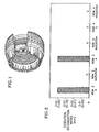
- FIG. 2 depicts the oxidation damage (or lack thereof) of the various segments. Oxidation damage was determined by visually inspecting each segment for any burned/oxidized portions and determining the approximate severity of damage.
- the left-most bar (A) on the chart represents the performance of a coating consisting of zirconia partially stabilized with 6-8 weight percent yttria plasma deposited in air on a NCoCrAlY bond coat (nominal composition, in weight percent, of 23Co, 17Cr, 12.5Al, 0.45Y, balance Ni) which was also plasma deposited in air.
- the thickness of the bond coat was about 0.007 inches (0.178 mm), and the thickness of the ceramic material was about 0.014 inches (0.356 mm).
- This Sample A was applied to 5 of 10 segments on row 2 of the outer liner. Sample A did not include any intentionally introduced porosity.
- a preferred insulating thermal barrier coating system of the present invention was applied to the remaining 5 segments in row 2 by first plasma spraying, in air, the bond coat.
- the material of the bond coat had nominal composition, in weight percent, of 23Co, 17Cr, 12.5Al, 0.45Y, balance Ni.
- a porous ceramic material comprising zirconia partially stabilized with 6 to 8 weight percent yttria was air plasma sprayed upon the bond coat. Porosity was intentionally created within the ceramic material through the incorporation of about 2.0 weight percent polyester powder (60 micron (.06 mm) nominal particle size).
- the thickness of the bond coat and the ceramic material was substantially the same as that of Sample A.
- the coating of Sample A was also applied to 4 of 7 segments tested on row 3 of the outer liner.
- the preferred insulating thermal barrier coating system of the present invention was applied to the remaining 3 segments tested, as described above except the thickness of the bond coat and the thickness of the ceramic material was increased by a factor of 1.5 each.
- Four (4) out of 4 segments coated with Sample A coating exhibited trailing edge oxidation damage up to 0.40 inches (1.02 mm).
- Zero (0) out of 3 segments coated in accordance with the preferred embodiment of the present invention exhibited trailing edge oxidation.
- FIG. 3 schematically illustrates a cross-section of a modern gas turbine engine with a first stage turbine vane support area 10 encircled.
- a preferred insulating thermal barrier coating system 12 of the present invention was applied to the inner diameter surface of a first stage turbine vane support 14, as shown in FIG. 4.
- the substrate material of the first vane support 14 was 19.5Cr, 13.5Co, 4.25Mo, 3.0Ti, 1.4Al, 0.07Zr, 0.007B, balance Ni (AMS 5707 (Waspaloy)).
- the inner diameter of the first stage vane support 14 was cleaned and conditioned by aluminum oxide dry blasting prior to application of the insulating thermal barrier coating system 12.
- the insulating thermal barrier coating system 12 was then applied by first plasma spraying, in air, a preferred bond coat of the present invention to a thickness of about .003 inches (.076 mm).
- the material of the bond coat had nominal composition, in weight percent, of 23Co, 17Cr, 12.5Al, 0.45Y, balance being Ni apart from inconsequential and impurities and powder particle sizes within the range -170+325 US std. sieve. (44 to 88pm).
- porous ceramic material comprising zirconia partially stabilized with 6 to 8 weight percent yttria was air plasma sprayed upon the bond coat.
- the substrate temperature was maintained at less than 500°F (260°C).
- the size of the ceramic powder particles was about 50 microns (.05 mm) in mean diameter. Porosity was intentionally created within the ceramic material through the incorporation of about 2.0 weight percent polyester powder (60 micron (.06 mm) nominal particle size). The thickness of the ceramic material varied between about 25 and 35 mils (.635 and .889 mm).
- the article was then subjected to a 935 cycle engine test simulating flights at various maximum engine power conditions.
- the article exhibited no cracking upon visual inspection as well as upon fluorescent penetrant inspection.
- FIG. 5 further illustrates the significant benefits of the present invention.
- FIG. 5 depicts the life of the first stage turbine vane support 14 with and without a preferred insulating thermal barrier coating system 12 of the present invention versus temperature.
- simulated engine operation at a first stage turbine vane support substrate temperature of approximately 1600°F (871°C) as measured by thermocouples resulted in a predicted life of 2000 cycles for an uncoated first stage turbine vane support (AMS 5707 (Waspaloy)).
- AMS 5707 uncoated first stage turbine vane support
- the significance of operation at 1600°F (871°C) is that this temperature is well above the maximum allowable use temperature for AMS 5707.
- the substrate temperature ofthe first stage turbine vane support 14 was calculated to be reduced to approximately 1450°F (788°C) and an extended predicted life of 19,000 cycles under the same operating conditions was achieved.
- the extension of life by 17,000 cycles illustrates the tremendous insulating benefit of the present invention.
Description
- This invention relates to ceralic thermal barrier coating systems used to insulate substrates from elevated temperatures.
- Modern gas turbine engines, particularly those used in aircraft, operate at high rotational speeds and high temperatures for increased performance and efficiency. There is a high demand for improved performance and efficiency because of the desire to increase the range an aircraft can fly without stopping to refuel.
- Today's modern gas turbine engines rely primarily on nickel base and cobalt base superalloys for the material ofthe engine components in many critical applications. As operating temperatures increase, however, the property limits of the base alloy materials are being approached.
- Accordingly, attempts have been made to use coatings to protect certain components within the engine from the harsh operating environment. In particular, ceramic thermal barrier coatings are increasingly employed to protect turbine components, such as turbine blades, thereby extending the life of the blades and permitting enhanced fuel economy. Such protective coatings are necessary because some components in the turbine section must withstand high stresses and corrosive gas streams at temperatures greater than 2500°F (1371°C).
- Many ceramic thermal barrier coating system applications, however, include a metallic bond coat which requires a bond coat adherence high temperature heat treatment to maximize the strength of the bond between the substrate and the metallic bond coat. While the bond coat adherence heat treatment is conventionally applied after application of the ceramic material, it could be performed prior to depositing the ceramic material. An exemplary bond coat adherence high temperature heat treatment includes heating a ceramic coated substrate in a nonoxidizing environment for one to ten hours at 1800°F (982°C) to 2050°F (1121°C).
- This requirement may not be an undue burden for the coating of 3 inch to 6 inch (7.6 cm-15.2 cm) turbine blades and may in fact be required due to the high temperature, dynamic environment in which the turbine blades operate. However, application of this type of ceramic thermal barrier coating system and its high temperature heat treatment is an undesirable option for many other components in need of protection. For example, sheet metal components, such as the exemplary combustor shown in FIG 1, which are inconveniently large and prone to warpage mitigates against the use of such a bond coat adherence high temperature heat treatment and thus mitigates against the use of a thermal barrier coating system employing such a heat treatment.
- In addition, we recently encountered the need to thermally insulate a component without subjecting it to a bond coat adherence high temperature heat treatment because of the need to insulate it in an as machined condition, without any subsequent machining to size, to avoid component distortion. However, to our knowledge we are not aware of an existing thermal barrier coating system having superior insulating characteristics which does not require such a high temperature heat treatment to successfully bond the metallic bond coat to the substrate.
- It is known from EP-A-0266299 to provide a ceramic thermal barrier coating system comprising the features of the pre-amble of claim 1. By avoiding the need for a bond coat adherence heat treatment, the coating system can be applied to large components or components which are prone to distortion during heat treatment. A thin abradable ceramic air seal system is also known from US-A-4936745 comprising a bond coat and a ceramic layer. A high temperature bond coat adherence heat treatment is required to maximise the strength of the bond coat to the substrate.
- Accordingly, what is needed is a thermal barrier coating system requiring no bond coat adherence high temperature heat treatment and having enhanced insulating capabilities such that it may be applied to gas turbine engine components of varied shape, thickness and size.
- It is an object of the present invention to provide an insulating thermal barrier coating system for a metallic substrate.
- It is a further object of the present invention to provide an insulating thermal barrier coating system as above requiring no bond coat adherence high temperature heat treatment to form a bond between the metallic bond coat and the metallic substrate to which the metallic bond coat is applied and having enhanced insulating capabilities.
- It is yet a further object of the present invention to provide a method of insulating a metallic substrate.
- Viewed from a first aspect, the present invention provides an insulating thermal barrier coating system consisting of:
- a) a metallic substrate comprising a nickel base or cobalt base superalloy material;
- b) a metallic bond coat on the metallic substrate, said metallic bond coat consisting of 15-40 wt. % Co, 10-40 wt. % Cr, 6-15 wt. % Al, 0-0.7 wt. % Si, 0-2.0 wt. % Hf, 0.01-1.0 wt. % Y, balance being Ni apart from inconsequential impurities, wherein the metallic bond coat has received no bond coat adherence heat treatment to form a bond between the metallic bond coat and the metallic substrate; and
- c) a ceramic insulating thermal barrier coating on the bond coat, the ceramic insulating coating comprising zirconia partially stabilised with 6-8 wt. % yttria, characterised in that said ceramic insulating thermal barrier coating has a porosity of between 20-35 volume percent.
-
- Preferably the ceramic insulating thermal barrier coating has a thickness of between about 25-50 mils (0.635-1.27 mm). Porosity is intentionally created within the ceramic insulating thermal barrier coating, for example, by incorporating a small amount of polyester powder within the ceramic material.
- Viewed from a second aspect, the present invention provides a method of insulating a metallic substrate consisting of:
- a) providing a clean metallic substrate;
- b) depositing a metallic bond coat on said metallic substrate, said metallic bond coat receiving no bond coat adherence heat treatment to form a bond between the metallic bond coat and the metallic substrate, said metallic bond coat consisting of 15-40 wt. % Co, 10-40 wt. % Cr, 6-15 wt. % Al, 0-0.7 wt. % Si, 0-2.0 wt. % Hf, 0.01-1.0 wt. % Y, balance being Ni apart from inconsequential impurities; and
- c) depositing a ceramic insulating thermal barrier coating on the metallic bond coat, the ceramic insulating thermal barrier coating comprising zirconia partially stabilised with 6-8 wt. % yttria, characterised in that porosity is intentionally created in the ceramic insulating thermal barrier coating at a level of between 20-35 volume percent.
-
- In the case of certain substrate materials, it may be possible to avoid the need for a bond coat altogether. Thus, viewed from a third aspect, the present invention provides a coated article comprising a metallic substrate selected from the group consisting of Ni and Co base superalloys having thereupon an insulating thermal barrier coating consisting of a porous ceramic insulating layer comprising zirconia partially stabilized with 6-8 wt. % yttria, wherein the porous ceramic insulating layer has a porosity between 20-35 volume percent, wherein the substrate has been roughened prior to receiving the insulating layer to ensure bonding of the insulating layer to the substrate.
- Certain preferred embodiments of the present invention will now be described by way of example only and with reference to the accompanying drawings, in which:
- FIG. 1 is a schematic illustration of a gas turbine combustor;
- FIG. 2 is a bar chart depicting oxidation resistance performance of various thermal barrier coating systems applied to different segments of a gas turbine combustor;
- FIG. 3 is a cross-section of a portion of a modern gas turbine engine with a first stage turbine vane support area encircled;
- FIG. 4 is an enlarged view of the first vane support shown in FIG. 3; and
- FIG. 5 is a logarithmic graph depicting life versus temperature for an uncoated first stage turbine vane support and that of a first stage turbine vane support coated with a preferred insulating thermal barrier coating system of the present invention.
-
- According to the present invention an insulating thermal barrier coating system is applied to a metallic substrate. The substrate may be made of a conventional nickel base or cobalt base superalloy material and may be cast and machined to desired final shape/size using known techniques.
- Prior to applying the insulating thermal barrier coating system to the substrate, the substrate is prepared to receive the coating system. Preparation is conventional and includes cleaning the substrate surface to remove contamination. Suitable cleaning methods include, but are not limited to, aluminum oxide grit blasting. Preferably, the surface is roughened by the cleaning process to aid the adherence of the subsequently applied bond coat to the substrate.
- A metallic bond coat requiring no bond coat adherence high temperature heat treatment is then applied to the substrate. As wilt become apparent from the description set forth herein, a preferred feature of the present invention is use of a metallic bond coat receiving no such high temperature or diffusion heat treatment.
- Thus, the invention is particularly advantageous for insulating metallic components prone to distortion during heat treatment or those requiring insulation in an as machined condition. The invention is also particularly advantageous for insulating materials whose properties may not be capable of withstanding exposure to such a high temperature heat treatment without, for example, losing strength or oxidizing. Thus, the invention is advantageous for insulating metallic components which are intolerant of high temperature bond coat diffusion heat treatment cycles.
- The invention has particular utility in insulating static gas turbine engine components, such as turbine vanes and turbine vane supports, because these components do not undergo the centrifugal forces as do turbine blades.
- Yet another significant advantage is the cost savings associated with eliminating a subsequent heat treatment step.
- A metallic bond coat of a NiCoCrAlY material is employed, particularly if oxidation resistance is desired. In the context of this invention, Ni denotes nickel, Co denotes cobalt, Cr denotes chromium, Al denotes aluminum and Y denotes yttrium. The bond coat material has a composition falling within the broad weight percent range of 15-40Co, 10-40Cr, 6-15Al, 0-.7Si, 0-2.0Hf, 0.01-1.0Y, balance essentially Ni. Preferably, the bond coat material has a composition falling within the weight percent range of 20-26Co, 15-19Cr, 11.5-13.5Al, 0-.7Si, 0-2.0Hf, 0.20-0.70Y, balance essentially Ni. The particle size of the bond coat material is preferably within the range -170+325 US std. sieve (44 to 88pm).
- The bond coat thickness may be between about 0.001-0.015 inches (0.025 0.381 mm). Preferably the thickness of the bond coat is between about 0.005-0.009 inches (0.127-0.229 mm). The bond coat is preferably plasma sprayed, in air, on the surface of the substrate to be protected. Other deposition techniques, including but not limited to, high velocity oxy fuel (HVOF) spraying or cathodic arc deposition may be employed.
- Preferably, the surface topography of the bond coat is such that it is suitable to receive the subsequently applied ceramic material. Preferably, the metallic bond coat is plasma sprayed, in air, which will yield a roughened bond coat surface.
- Upon the above described metallic bond coat, a porous ceramic material comprising zirconia partially stabilized with 6 to 8 percent (by weight) yttria is then applied. The ceramic material is preferably plasma sprayed in air and the substrate temperature is maintained at less than 500°F (260°C). Other deposition techniques, including but not limited to, high velocity oxy fuel (HVOF) may also be employed.
- The ceramic particle size is between about 5 and about 180 microns (.005 and about .18 mm) and preferably about 50 microns (.05 mm) mean diameter. Porosity is intentionally created within the ceramic coating. Preferably, porosity is achieved by incorporating between about 1-12 weight percent polyester powder within the ceramic. We most prefer the use of 1.5 to 3.0 weight percent polyester powder (60 micron (.06 mm) nominal particle size) with the ceramic to produce a porosity on the order of 20 to 30 volume percent. High porosity levels, in excess of about 35 volume percent, may produce coatings susceptible to erosion damage.
- An advantage of intentionally introducing the above described porosity is that it provides spall resistance which allows the ceramic material to be applied at an increased thickness. The thickness of the ceramic coating can range from 25 to 50 mils (.635 to 1.27 mm) and preferably from 25 to 35 mils (.635 to .889 mm).
- In another embodiment of the invention, other ceramic materials having low thermal conductivity, including but not limited to, zirconia fully stabilized with yttria, zirconia stabilized with ceria, or ceria may be substituted for the above described zirconia partially stabilized with yttria.
- In yet another embodiment of the present invention, the above described ceramic layer may be deposited directly on the metallic substrate, without the use of a bond coat. This embodiment may be feasible for insulation of oxidation resistant alloys, for example, alloys including active elements, such as yttrium, calcium, or magnesium, or alloys made from low sulfur bearing materials, or alloys subsequently desulfurized. For marginally oxidation resistant alloys, direct bonding of the ceramic layer may also be feasible if the substrate is pre-oxidized in a controlled manner to grow a strongly adherent oxide interlayer. With the elimination of the bond coat, this embodiment may be advantageous for static applications in a nonerosive environment or where the substrate temperature can be maintained at less than about 1800°F (982°C). For proper bonding of the ceramic material to the substrate, however, it may be necessary to roughen the surface of the substrate by techniques, including but not limited to, grit blasting. This embodiment is primarily suitable for operating environments in which the coating is not subjected to excessive thermal or mechanical stress at the substrate/ceramic interface.
- The present invention will now be described by way of examples which are meant to be exemplary rather than limiting.
- Various ceramic thermal barrier coating systems, including preferred embodiments of the present invention, were applied to cast combustor segments. The material of each segment was made from the same base alloy having a nominal composition, in weight percent, of 8.0Cr, 10Co, 6.0Mo, 6.0Al, 4.3Ta, 1.15Hf, 1.0Ti, 0.015B, 0.08Zr, balance Ni (B-1900+Hf). The test segments occupied portions of
rows - The liner was then subjected to a severe test employing conditions more demanding than those encountered in normal operation of a gas turbine engine. The test included 1300 cycles. The first 300 cycles were run under normal takeoff conditions; 1000 of the cycles included 5.5 minutes at maximum allowable operating temperature which accelerated the oxidation rate per cycle. It should be noted that the combustion process is such that flame conditions in the region of
rows row 4. - The benefits of the present invention are clearly illustrated in FIG. 2 FIG. 2 depicts the oxidation damage (or lack thereof) of the various segments. Oxidation damage was determined by visually inspecting each segment for any burned/oxidized portions and determining the approximate severity of damage.
- The left-most bar (A) on the chart represents the performance of a coating consisting of zirconia partially stabilized with 6-8 weight percent yttria plasma deposited in air on a NCoCrAlY bond coat (nominal composition, in weight percent, of 23Co, 17Cr, 12.5Al, 0.45Y, balance Ni) which was also plasma deposited in air. The thickness of the bond coat was about 0.007 inches (0.178 mm), and the thickness of the ceramic material was about 0.014 inches (0.356 mm). This Sample A was applied to 5 of 10 segments on
row 2 of the outer liner. Sample A did not include any intentionally introduced porosity. - A preferred insulating thermal barrier coating system of the present invention was applied to the remaining 5 segments in
row 2 by first plasma spraying, in air, the bond coat. The material of the bond coat had nominal composition, in weight percent, of 23Co, 17Cr, 12.5Al, 0.45Y, balance Ni. Next a porous ceramic material comprising zirconia partially stabilized with 6 to 8 weight percent yttria was air plasma sprayed upon the bond coat. Porosity was intentionally created within the ceramic material through the incorporation of about 2.0 weight percent polyester powder (60 micron (.06 mm) nominal particle size). The thickness of the bond coat and the ceramic material was substantially the same as that of Sample A. - Three (3) out of 5 segments coated with Sample A exhibited trailing edge oxidation damage up to .040 inches (1.02 mm) in depth. None of the 5 segments coated in accordance with the preferred embodiment of the present invention exhibited trailing edge oxidation damage.
- The coating of Sample A, as described above, was also applied to 4 of 7 segments tested on
row 3 of the outer liner. The preferred insulating thermal barrier coating system of the present invention was applied to the remaining 3 segments tested, as described above except the thickness of the bond coat and the thickness of the ceramic material was increased by a factor of 1.5 each. Four (4) out of 4 segments coated with Sample A coating exhibited trailing edge oxidation damage up to 0.40 inches (1.02 mm). Zero (0) out of 3 segments coated in accordance with the preferred embodiment of the present invention exhibited trailing edge oxidation. - The coating of Sample A, as described above, was applied to 3 of 6 segments tested on
row 4 of the outer liner. The preferred insulating thermal barrier coating system of the present invention, as inrow 2, was applied to the remaining 3 segments tested. None of the 3 segments coated with Sample A coating exhibited trailing edge oxidation damage. Similarly, 0 out of 3 segments coated in accordance with the preferred embodiment of present invention exhibited trailing edge oxidation. - It can be seen that the coating performance of the preferred embodiments in terms of oxidation degradation resistance meets and even exceeds that of the Sample A coating system when tested under conditions which are more severe than those normally encountered in engine operation. This example also illustrates the superior insulating capabilities of the present invention.
- FIG. 3 schematically illustrates a cross-section of a modern gas turbine engine with a first stage turbine
vane support area 10 encircled. A preferred insulating thermalbarrier coating system 12 of the present invention was applied to the inner diameter surface of a first stageturbine vane support 14, as shown in FIG. 4. The substrate material of thefirst vane support 14 was 19.5Cr, 13.5Co, 4.25Mo, 3.0Ti, 1.4Al, 0.07Zr, 0.007B, balance Ni (AMS 5707 (Waspaloy)). The inner diameter of the firststage vane support 14 was cleaned and conditioned by aluminum oxide dry blasting prior to application of the insulating thermalbarrier coating system 12. - The insulating thermal
barrier coating system 12 was then applied by first plasma spraying, in air, a preferred bond coat of the present invention to a thickness of about .003 inches (.076 mm). The material of the bond coat had nominal composition, in weight percent, of 23Co, 17Cr, 12.5Al, 0.45Y, balance being Ni apart from inconsequential and impurities and powder particle sizes within the range -170+325 US std. sieve. (44 to 88pm). - Next a porous ceramic material comprising zirconia partially stabilized with 6 to 8 weight percent yttria was air plasma sprayed upon the bond coat. The substrate temperature was maintained at less than 500°F (260°C).
- The size of the ceramic powder particles was about 50 microns (.05 mm) in mean diameter. Porosity was intentionally created within the ceramic material through the incorporation of about 2.0 weight percent polyester powder (60 micron (.06 mm) nominal particle size). The thickness of the ceramic material varied between about 25 and 35 mils (.635 and .889 mm).
- The article was then subjected to a 935 cycle engine test simulating flights at various maximum engine power conditions. The article exhibited no cracking upon visual inspection as well as upon fluorescent penetrant inspection.
- Another article coated with a preferred insulating thermal barrier coating system of the present invention was tested in an engine operating for five minutes at an exhaust gas temperature approximately 75°F (24°C) above the maximum temperature encountered in normal engine operation. This was a most severe test employing conditions which are more demanding than those normally encountered during typical gas turbine engine operation. This article also exhibited no cracking upon visual inspection as well as upon fluorescent penetrant inspection.
- FIG. 5 further illustrates the significant benefits of the present invention. FIG. 5 depicts the life of the first stage
turbine vane support 14 with and without a preferred insulating thermalbarrier coating system 12 of the present invention versus temperature. As can be seen from the graph, simulated engine operation at a first stage turbine vane support substrate temperature of approximately 1600°F (871°C) as measured by thermocouples resulted in a predicted life of 2000 cycles for an uncoated first stage turbine vane support (AMS 5707 (Waspaloy)). The significance of operation at 1600°F (871°C) is that this temperature is well above the maximum allowable use temperature for AMS 5707. - However, by coating the inner diameter of the first stage
turbine vane support 14 with a preferred insulating thermalbarrier coating system 12 of the present invention, the substrate temperature ofthe first stageturbine vane support 14 was calculated to be reduced to approximately 1450°F (788°C) and an extended predicted life of 19,000 cycles under the same operating conditions was achieved. The extension of life by 17,000 cycles illustrates the tremendous insulating benefit of the present invention.
Claims (22)
- An insulating thermal barrier coating system consisting of:a) a metallic substrate comprising a nickel base or cobalt base superalloy material;b) a metallic bond coat on the metallic substrate, said metallic bond coat consisting of 15-40 wt. % Co, 10-40 wt. % Cr, 6-15 wt. % Al, 0-0.7 wt. % Si, 0-2.0 wt. % Hf, 0.01-1.0 wt. % Y, balance being Ni apart from inconsequential impurities, wherein the metallic bond coat has received no bond coat adherence heat treatment to form a bond between the metallic bond coat and the metallic substrate; andc) a ceramic insulating thermal barrier coating on the bond coat, the ceramic insulating coating comprising zirconia partially stabilised with 6-8 wt. % yttria, characterised in that said ceramic insulating thermal barrier coating has a porosity of between 20-35 volume percent.
- A system as claimed in claim 1, wherein said metallic bond coat has a thickness between 0.001-0.015 inches (0.025-0.381 mm).
- A system as claimed in claim 1 or 2, wherein the ceramic insulating thermal barrier coating has a thickness between 25-50 mils (0.635-1.27 mm).
- A system as claimed in claim 1, 2 or 3, wherein said metallic bond coat consists of 20-26 wt. % Co, 15-19 wt. % Cr, 11.5-13.5 wt. % Al, 0-0.7 wt. % Si, 0-2.0 wt. % Hf, 0.20-0.70 wt. % Y, balance being Ni apart from inconsequential impurities.
- A system as claimed in claim 4, wherein said metallic bond coat consists of 23 wt. % Co, 17 wt. % Cr, 12.5 wt. % Al, 0.45 wt. % Y, balance being Ni apart from inconsequential impurities.
- A gas turbine engine component comprising the insulating thermal barrier coating system of any preceding claim.
- A gas turbine engine component as claimed in claim 6, wherein the component is a first stage turbine vane support.
- A gas turbine engine component as claimed in claim 6, wherein the component is a combustor liner.
- A gas turbine engine component as claimed in claim 6, wherein the component is a segment of a combustor.
- A gas turbine engine component as claimed in any of claims 6 to 9, wherein said metallic substrate is roughened prior to receiving the ceramic insulating thermal barrier coating to ensure bonding of the ceramic insulating coating to the substrate, and wherein said ceramic insulating thermal barrier coating has been exposed to operational heat.
- A method of insulating a metallic substrate consisting of:a) providing a clean metallic substrate;b) depositing a metallic bond coat on said metallic substrate, said metallic bond coat receiving no bond coat adherence heat treatment to form a bond between the metallic bond coat and the metallic substrate, said metallic bond coat consisting of 15-40 wt. % Co, 10-40 wt. % Cr, 6-15 wt. % Al, 0-0.7 wt. % Si, 0-2.0 wt. % Hf, 0.01-1.0 wt. % Y, balance being Ni apart from inconsequential impurities; andc) depositing a ceramic insulating thermal barrier coating on the metallic bond coat, the ceramic insulating thermal barrier coating comprising zirconia partially stabilised with 6-8 wt. % yttria, characterised in that porosity is intentionally created in the ceramic insulating thermal barrier coating at a level of between 20-35 volume percent.
- A method as claimed in claim 11, wherein the porous ceramic insulating thermal barrier coating is deposited to a thickness of between 25-50 mils (0.635-1.27 mm)
- A method as claimed in claim 11 or 12, wherein said porous ceramic insulating thermal barrier coating is formed by depositing a ceramic layer comprising zirconia partially stabilised with 6-8 wt. % yttria and 1-12 wt. % polyester and subsequently exposing said ceramic layer to operational heat.
- A method as claimed in claim 13, wherein said porous ceramic layer is formed by depositing a ceramic layer comprising zirconia partially stabilised with 6-8 wt. % yttria and 1.5-3 wt. % polyester.
- A method as claimed in any of claims 11 to 14, wherein the substrate surface is cleaned by grit blasting prior to depositing the metallic bond coat.
- A method as claimed in any of claims 11 to 15, wherein the metallic bond coat is deposited by plasma spray, in air.
- A method as claimed in any of claims 11 to 15, wherein the metallic bond coat is deposited by high velocity oxy fuel spraying.
- A method as claimed in any of claims 11 to 15, wherein the metallic bond coat is deposited by cathodic arc deposition.
- A coated article comprising a metallic substrate selected from the group consisting of Ni and Co base superalloys having thereupon an insulating thermal barrier coating consisting of a porous ceramic insulating layer comprising zirconia partially stabilized with 6-8 wt. % yttria, wherein the porous ceramic insulating layer has a porosity of between 20-35 volume percent, wherein the substrate has been roughened prior to receiving the insulating layer to ensure bonding of the insulating layer to the substrate.
- A coated article as claimed in claim 19, wherein the coated article is a gas turbine engine component.
- A coated article as claimed in claim 20, wherein the gas turbine engine component is a first stage turbine vane support.
- A coated article as claimed in claim 20, wherein the gas turbine engine component is a combustor liner.
Applications Claiming Priority (2)
| Application Number | Priority Date | Filing Date | Title |
|---|---|---|---|
| US67146696A | 1996-06-27 | 1996-06-27 | |
| US671466 | 1996-06-27 |
Publications (3)
| Publication Number | Publication Date |
|---|---|
| EP0816526A2 EP0816526A2 (en) | 1998-01-07 |
| EP0816526A3 EP0816526A3 (en) | 1998-01-28 |
| EP0816526B1 true EP0816526B1 (en) | 2001-10-17 |
Family
ID=24694632
Family Applications (1)
| Application Number | Title | Priority Date | Filing Date |
|---|---|---|---|
| EP97304676A Revoked EP0816526B1 (en) | 1996-06-27 | 1997-06-27 | Insulating thermal barrier coating system |
Country Status (3)
| Country | Link |
|---|---|
| EP (1) | EP0816526B1 (en) |
| JP (2) | JP3258599B2 (en) |
| DE (1) | DE69707365T2 (en) |
Cited By (6)
| Publication number | Priority date | Publication date | Assignee | Title |
|---|---|---|---|---|
| DE102005053531A1 (en) * | 2005-11-08 | 2007-05-10 | Man Turbo Ag | Heat-insulating protective layer for a component within the hot gas region of a gas turbine |
| WO2007115839A2 (en) | 2006-04-06 | 2007-10-18 | Siemens Aktiengesellschaft | Layered thermal barrier coating with a high porosity, and a component |
| DE102010033686A1 (en) | 2010-08-06 | 2012-02-09 | Lufthansa Technik Ag | Gas turbine for use as turbofan engine, for aircraft in e.g. hot countries, has heat insulating layer provided on surface of blades of guide vane ring along flowing direction of working gas downstream behind profile center of gravity |
| US9151175B2 (en) | 2014-02-25 | 2015-10-06 | Siemens Aktiengesellschaft | Turbine abradable layer with progressive wear zone multi level ridge arrays |
| US9243511B2 (en) | 2014-02-25 | 2016-01-26 | Siemens Aktiengesellschaft | Turbine abradable layer with zig zag groove pattern |
| US10196920B2 (en) | 2014-02-25 | 2019-02-05 | Siemens Aktiengesellschaft | Turbine component thermal barrier coating with crack isolating engineered groove features |
Families Citing this family (23)
| Publication number | Priority date | Publication date | Assignee | Title |
|---|---|---|---|---|
| AU4505399A (en) * | 1999-06-02 | 2000-12-28 | Abb Research Ltd | Coating composition for high temperature protection |
| US6607789B1 (en) * | 2001-04-26 | 2003-08-19 | General Electric Company | Plasma sprayed thermal bond coat system |
| EP1411210A1 (en) * | 2002-10-15 | 2004-04-21 | ALSTOM Technology Ltd | Method of depositing an oxidation and fatigue resistant MCrAIY-coating |
| KR100509118B1 (en) * | 2002-10-28 | 2005-08-19 | 한국전력공사 | Pre-oxidation treatment method for life extension of thermal barrier coating |
| US6803135B2 (en) | 2003-02-24 | 2004-10-12 | Chromalloy Gas Turbine Corporation | Thermal barrier coating having low thermal conductivity |
| US6764779B1 (en) | 2003-02-24 | 2004-07-20 | Chromalloy Gas Turbine Corporation | Thermal barrier coating having low thermal conductivity |
| US20050153160A1 (en) | 2004-01-12 | 2005-07-14 | Yourong Liu | Durable thermal barrier coating having low thermal conductivity |
| US7927722B2 (en) * | 2004-07-30 | 2011-04-19 | United Technologies Corporation | Dispersion strengthened rare earth stabilized zirconia |
| US7246996B2 (en) * | 2005-01-04 | 2007-07-24 | General Electric Company | Methods and apparatus for maintaining rotor assembly tip clearances |
| EP1818419A1 (en) * | 2006-01-16 | 2007-08-15 | Siemens Aktiengesellschaft | Alloy, protective layer and component |
| DE112008000455A5 (en) * | 2007-03-14 | 2009-12-03 | Fraunhofer-Gesellschaft zur Förderung der angewandten Forschung e.V. | Layer system and method for its production |
| US9725797B2 (en) | 2008-04-30 | 2017-08-08 | United Technologies Corporation | Process for forming an improved durability thick ceramic coating |
| FR2947568B1 (en) * | 2009-07-02 | 2011-07-22 | Snecma | THERMAL PROTECTION COATING FOR A TURBOMACHINE PART AND METHOD FOR PRODUCING THE SAME |
| DE102012200560B4 (en) | 2012-01-16 | 2014-08-21 | Fraunhofer-Gesellschaft zur Förderung der angewandten Forschung e.V. | A method of producing a ceramic layer on a surface formed of a Ni-based alloy and a ceramic layer article |
| EP2644824A1 (en) | 2012-03-28 | 2013-10-02 | Siemens Aktiengesellschaft | Method for producing and restoring of ceramic thermal barrier coatings in gas turbines and related gas turbine |
| US9586376B2 (en) | 2012-04-09 | 2017-03-07 | Smith International, Inc. | High pressure high temperature cell |
| US20130266678A1 (en) | 2012-04-09 | 2013-10-10 | Smith International, Inc. | Thermal insulation layer and pressure transfer medium for high pressure high temperature cell |
| WO2015130527A2 (en) | 2014-02-25 | 2015-09-03 | Siemens Aktiengesellschaft | Turbine component thermal barrier coating with depth-varying material properties |
| WO2016133581A1 (en) | 2015-02-18 | 2016-08-25 | Siemens Aktiengesellschaft | Turbine shroud with abradable layer having composite non-inflected triple angle ridges and grooves |
| EP3259452A2 (en) | 2015-02-18 | 2017-12-27 | Siemens Aktiengesellschaft | Forming cooling passages in combustion turbine superalloy castings |
| EP3333284A1 (en) * | 2016-12-08 | 2018-06-13 | Siemens Aktiengesellschaft | Nondestructive method to evaluate microstructure of segmented coatings |
| US20190169730A1 (en) * | 2017-12-04 | 2019-06-06 | General Electric Company | Methods of forming a porous thermal barrier coating |
| CN114107775B (en) * | 2021-11-17 | 2022-09-30 | 内蒙古科技大学 | Bonding layer alloy for turbine blade of aircraft engine and preparation method thereof |
Citations (1)
| Publication number | Priority date | Publication date | Assignee | Title |
|---|---|---|---|---|
| US4936745A (en) * | 1988-12-16 | 1990-06-26 | United Technologies Corporation | Thin abradable ceramic air seal |
Family Cites Families (5)
| Publication number | Priority date | Publication date | Assignee | Title |
|---|---|---|---|---|
| US4248940A (en) * | 1977-06-30 | 1981-02-03 | United Technologies Corporation | Thermal barrier coating for nickel and cobalt base super alloys |
| US4503130A (en) * | 1981-12-14 | 1985-03-05 | United Technologies Corporation | Prestressed ceramic coatings |
| IL84067A (en) * | 1986-10-30 | 1992-03-29 | United Technologies Corp | Thermal barrier coating system |
| US5536022A (en) * | 1990-08-24 | 1996-07-16 | United Technologies Corporation | Plasma sprayed abradable seals for gas turbine engines |
| US5350599A (en) * | 1992-10-27 | 1994-09-27 | General Electric Company | Erosion-resistant thermal barrier coating |
-
1997
- 1997-06-27 JP JP17138597A patent/JP3258599B2/en not_active Expired - Fee Related
- 1997-06-27 EP EP97304676A patent/EP0816526B1/en not_active Revoked
- 1997-06-27 DE DE69707365T patent/DE69707365T2/en not_active Revoked
-
2001
- 2001-10-02 JP JP2001306089A patent/JP3434504B2/en not_active Expired - Lifetime
Patent Citations (1)
| Publication number | Priority date | Publication date | Assignee | Title |
|---|---|---|---|---|
| US4936745A (en) * | 1988-12-16 | 1990-06-26 | United Technologies Corporation | Thin abradable ceramic air seal |
Cited By (6)
| Publication number | Priority date | Publication date | Assignee | Title |
|---|---|---|---|---|
| DE102005053531A1 (en) * | 2005-11-08 | 2007-05-10 | Man Turbo Ag | Heat-insulating protective layer for a component within the hot gas region of a gas turbine |
| WO2007115839A2 (en) | 2006-04-06 | 2007-10-18 | Siemens Aktiengesellschaft | Layered thermal barrier coating with a high porosity, and a component |
| DE102010033686A1 (en) | 2010-08-06 | 2012-02-09 | Lufthansa Technik Ag | Gas turbine for use as turbofan engine, for aircraft in e.g. hot countries, has heat insulating layer provided on surface of blades of guide vane ring along flowing direction of working gas downstream behind profile center of gravity |
| US9151175B2 (en) | 2014-02-25 | 2015-10-06 | Siemens Aktiengesellschaft | Turbine abradable layer with progressive wear zone multi level ridge arrays |
| US9243511B2 (en) | 2014-02-25 | 2016-01-26 | Siemens Aktiengesellschaft | Turbine abradable layer with zig zag groove pattern |
| US10196920B2 (en) | 2014-02-25 | 2019-02-05 | Siemens Aktiengesellschaft | Turbine component thermal barrier coating with crack isolating engineered groove features |
Also Published As
| Publication number | Publication date |
|---|---|
| JP3434504B2 (en) | 2003-08-11 |
| EP0816526A3 (en) | 1998-01-28 |
| DE69707365T2 (en) | 2002-07-11 |
| DE69707365D1 (en) | 2001-11-22 |
| JPH1068089A (en) | 1998-03-10 |
| JP3258599B2 (en) | 2002-02-18 |
| EP0816526A2 (en) | 1998-01-07 |
| JP2002180270A (en) | 2002-06-26 |
Similar Documents
| Publication | Publication Date | Title |
|---|---|---|
| EP0816526B1 (en) | Insulating thermal barrier coating system | |
| US4916022A (en) | Titania doped ceramic thermal barrier coatings | |
| US4880614A (en) | Ceramic thermal barrier coating with alumina interlayer | |
| US5015502A (en) | Ceramic thermal barrier coating with alumina interlayer | |
| US6284390B1 (en) | Thermal barrier coating system utilizing localized bond coat and article having the same | |
| JP3579267B2 (en) | Method for densifying bond coat for thermal barrier coating system and promoting bonding between particles | |
| EP1109948B1 (en) | Multilayer thermal barrier coating systems | |
| US6485845B1 (en) | Thermal barrier coating system with improved bond coat | |
| US6291084B1 (en) | Nickel aluminide coating and coating systems formed therewith | |
| EP1321542B1 (en) | Thermal barrier coating systems and materials | |
| US5514482A (en) | Thermal barrier coating system for superalloy components | |
| US6020075A (en) | Thermal barrier coating system | |
| EP0780484B1 (en) | Thermal barrier coated articles and method for coating | |
| JP3825114B2 (en) | Thermal barrier coating resistant to erosion and impact from particulates | |
| EP0987347B1 (en) | Thermal barrier coating system and method therefor | |
| GB2226050A (en) | Thin abradable ceramic air seal | |
| EP1411210A1 (en) | Method of depositing an oxidation and fatigue resistant MCrAIY-coating | |
| JP2008151128A (en) | Gas turbine engine component, its coating method and coating design method | |
| AU6774381A (en) | Columnar grain ceramic thermal barrier coatings | |
| CA2076118A1 (en) | Thermal barrier coating | |
| EP0886685A2 (en) | Improved thermal barrier coating system and methods | |
| US20020127112A1 (en) | Enhanced coating system for turbine airfoil applications | |
| US6929868B2 (en) | SRZ-susceptible superalloy article having a protective layer thereon | |
| EP0992614A1 (en) | Coatings for turbine components | |
| GB2285632A (en) | Thermal barrier coating system for superalloy components |
Legal Events
| Date | Code | Title | Description |
|---|---|---|---|
| PUAI | Public reference made under article 153(3) epc to a published international application that has entered the european phase |
Free format text: ORIGINAL CODE: 0009012 |
|
| PUAL | Search report despatched |
Free format text: ORIGINAL CODE: 0009013 |
|
| AK | Designated contracting states |
Kind code of ref document: A2 Designated state(s): DE FR GB |
|
| AX | Request for extension of the european patent |
Free format text: AL;LT;LV;RO;SI |
|
| AK | Designated contracting states |
Kind code of ref document: A3 Designated state(s): AT BE CH DE DK ES FI FR GB GR IE IT LI LU MC NL PT SE |
|
| AX | Request for extension of the european patent |
Free format text: AL;LT;LV;RO;SI |
|
| 17P | Request for examination filed |
Effective date: 19980703 |
|
| RBV | Designated contracting states (corrected) |
Designated state(s): DE FR GB |
|
| 17Q | First examination report despatched |
Effective date: 19990415 |
|
| GRAG | Despatch of communication of intention to grant |
Free format text: ORIGINAL CODE: EPIDOS AGRA |
|
| GRAG | Despatch of communication of intention to grant |
Free format text: ORIGINAL CODE: EPIDOS AGRA |
|
| GRAH | Despatch of communication of intention to grant a patent |
Free format text: ORIGINAL CODE: EPIDOS IGRA |
|
| GRAH | Despatch of communication of intention to grant a patent |
Free format text: ORIGINAL CODE: EPIDOS IGRA |
|
| GRAA | (expected) grant |
Free format text: ORIGINAL CODE: 0009210 |
|
| AK | Designated contracting states |
Kind code of ref document: B1 Designated state(s): DE FR GB |
|
| REF | Corresponds to: |
Ref document number: 69707365 Country of ref document: DE Date of ref document: 20011122 |
|
| REG | Reference to a national code |
Ref country code: GB Ref legal event code: IF02 |
|
| ET | Fr: translation filed | ||
| PLBI | Opposition filed |
Free format text: ORIGINAL CODE: 0009260 |
|
| PLBF | Reply of patent proprietor to notice(s) of opposition |
Free format text: ORIGINAL CODE: EPIDOS OBSO |
|
| 26 | Opposition filed |
Opponent name: ALSTOM (SWITZERLAND) LTD Effective date: 20020717 |
|
| PLBF | Reply of patent proprietor to notice(s) of opposition |
Free format text: ORIGINAL CODE: EPIDOS OBSO |
|
| PLBF | Reply of patent proprietor to notice(s) of opposition |
Free format text: ORIGINAL CODE: EPIDOS OBSO |
|
| PGFP | Annual fee paid to national office [announced via postgrant information from national office to epo] |
Ref country code: FR Payment date: 20040604 Year of fee payment: 8 |
|
| PGFP | Annual fee paid to national office [announced via postgrant information from national office to epo] |
Ref country code: DE Payment date: 20040630 Year of fee payment: 8 |
|
| PGFP | Annual fee paid to national office [announced via postgrant information from national office to epo] |
Ref country code: GB Payment date: 20040709 Year of fee payment: 8 |
|
| PLAY | Examination report in opposition despatched + time limit |
Free format text: ORIGINAL CODE: EPIDOSNORE2 |
|
| RDAF | Communication despatched that patent is revoked |
Free format text: ORIGINAL CODE: EPIDOSNREV1 |
|
| RDAG | Patent revoked |
Free format text: ORIGINAL CODE: 0009271 |
|
| STAA | Information on the status of an ep patent application or granted ep patent |
Free format text: STATUS: PATENT REVOKED |
|
| 27W | Patent revoked |
Effective date: 20041125 |
|
| GBPR | Gb: patent revoked under art. 102 of the ep convention designating the uk as contracting state |
Free format text: 20041125 |