EP0816265A2 - Apparatus for sorting cut sheets of glass - Google Patents
Apparatus for sorting cut sheets of glass Download PDFInfo
- Publication number
- EP0816265A2 EP0816265A2 EP97890115A EP97890115A EP0816265A2 EP 0816265 A2 EP0816265 A2 EP 0816265A2 EP 97890115 A EP97890115 A EP 97890115A EP 97890115 A EP97890115 A EP 97890115A EP 0816265 A2 EP0816265 A2 EP 0816265A2
- Authority
- EP
- European Patent Office
- Prior art keywords
- glass
- conveyor
- blanks
- shelf
- glass blanks
- Prior art date
- Legal status (The legal status is an assumption and is not a legal conclusion. Google has not performed a legal analysis and makes no representation as to the accuracy of the status listed.)
- Granted
Links
- 239000011521 glass Substances 0.000 title claims abstract description 82
- 238000009434 installation Methods 0.000 claims 1
- 238000000034 method Methods 0.000 description 2
- 238000010276 construction Methods 0.000 description 1
- 238000011144 upstream manufacturing Methods 0.000 description 1
Images


Classifications
-
- B—PERFORMING OPERATIONS; TRANSPORTING
- B65—CONVEYING; PACKING; STORING; HANDLING THIN OR FILAMENTARY MATERIAL
- B65G—TRANSPORT OR STORAGE DEVICES, e.g. CONVEYORS FOR LOADING OR TIPPING, SHOP CONVEYOR SYSTEMS OR PNEUMATIC TUBE CONVEYORS
- B65G49/00—Conveying systems characterised by their application for specified purposes not otherwise provided for
- B65G49/05—Conveying systems characterised by their application for specified purposes not otherwise provided for for fragile or damageable materials or articles
- B65G49/06—Conveying systems characterised by their application for specified purposes not otherwise provided for for fragile or damageable materials or articles for fragile sheets, e.g. glass
- B65G49/062—Easels, stands or shelves, e.g. castor-shelves, supporting means on vehicles
-
- B—PERFORMING OPERATIONS; TRANSPORTING
- B65—CONVEYING; PACKING; STORING; HANDLING THIN OR FILAMENTARY MATERIAL
- B65G—TRANSPORT OR STORAGE DEVICES, e.g. CONVEYORS FOR LOADING OR TIPPING, SHOP CONVEYOR SYSTEMS OR PNEUMATIC TUBE CONVEYORS
- B65G49/00—Conveying systems characterised by their application for specified purposes not otherwise provided for
- B65G49/05—Conveying systems characterised by their application for specified purposes not otherwise provided for for fragile or damageable materials or articles
- B65G49/06—Conveying systems characterised by their application for specified purposes not otherwise provided for for fragile or damageable materials or articles for fragile sheets, e.g. glass
- B65G49/067—Sheet handling, means, e.g. manipulators, devices for turning or tilting sheet glass
-
- B—PERFORMING OPERATIONS; TRANSPORTING
- B65—CONVEYING; PACKING; STORING; HANDLING THIN OR FILAMENTARY MATERIAL
- B65G—TRANSPORT OR STORAGE DEVICES, e.g. CONVEYORS FOR LOADING OR TIPPING, SHOP CONVEYOR SYSTEMS OR PNEUMATIC TUBE CONVEYORS
- B65G49/00—Conveying systems characterised by their application for specified purposes not otherwise provided for
- B65G49/05—Conveying systems characterised by their application for specified purposes not otherwise provided for for fragile or damageable materials or articles
- B65G49/06—Conveying systems characterised by their application for specified purposes not otherwise provided for for fragile or damageable materials or articles for fragile sheets, e.g. glass
- B65G49/068—Stacking or destacking devices; Means for preventing damage to stacked sheets, e.g. spaces
Definitions
- the invention relates to a device for sorting Glass blanks, with a lifting device, to be conveyed horizontally Almost erect glass blanks vertically and with a conveyor through which erect Glass cuts according to any order criteria Fan trolleys are fed and parked in these.
- Such a device is known from EP 477 163 A.
- the well-known sorting device in which a variety of Trolley used, is preferred in connection with a glass cutting machine used, such as from DE 43 05 826 A is known.
- the problem with the known sorting devices is that that the sorting of unnecessary glass blanks (Remnants) and damaged glass blanks from an intervention by Hand out of need. Furthermore, it has proven to be disadvantageous that sometimes problems arise when it takes a long time up to several according to the selected order criteria glass cuts belonging to a certain group (e.g. the two Blanks for producing an insulating glass pane) from the Glass cutting system can be supplied.
- a certain group e.g. the two Blanks for producing an insulating glass pane
- the invention has for its object a device for Sorting glass blanks of the type mentioned at the beginning to improve so that the sorting not needed or damaged glass blanks is easily possible and that additional There is buffer capacity.
- the lifting device for straightening up the glass blanks conveyed horizontally not as known from EP 477 163 A, only on one side a conveyor assigned to the glass blanks to the compartment trolley, but the other end of the lifting device is a buffer memory, e.g. in the form of a shelf, assigned.
- a buffer memory e.g. in the form of a shelf
- This buffer memory also allows one of its compartments to be used To set up equipment for conveying glass blanks, so that damaged and / or unnecessary blanks (remnants) in a collection container for glass cuts that are not required or damaged glass can be conveyed.
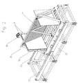
- a device 1 shown in FIG. 1 for Erecting in the direction of arrow 2 from a glass cutting machine, for example a glass cutting system 50 (FIG. 7) the type known from DE 43 05 826 A, glass blanks fed horizontally.
- the intermediate conveyor 10 instructs a conveyor, e.g. a conveyor belt 11, on, and is in the direction of the double arrow 12 on and adjustable.
- the glass blanks from the intermediate conveyor 10 as is known in EP 477 163 A, in Direction of arrow 3 in one of several compartment trolleys 60 (Fig. 7) transported or otherwise processed.
- the intermediate conveyor 10 is adjustable in height, can Glass blanks after moving from device 1 to the Intermediate conveyor 10 have been moved, as far as lowered, that its bottom horizontal edge is at the height of the bottom End of the compartments is in the compartment trolley 60.
- a buffer memory 20th arranged.
- This buffer memory 20 is in the exemplary embodiment designed as a shelf.
- the buffer memory 20 has a carriage 21, which is on a base 22 in the direction of the double arrow 23 is displaceable. In the car 21 are by tensioned ropes (preferably equipped with sleeves subjects formed according to EP 477 163 A) (for clarity only individual parts are shown).
- a Compartment, e.g. the first compartment has one with rollers Support wall 24 and is as a compartment for conveying through Glass blanks is formed by the buffer memory 20.
- the carriage 21 is opposite its base 22, as mentioned, slidable across from the desired subject the level of funding of the facility 1 or the removal conveyor 30 align so that a glass blank in a selected Tray of the buffer memory 20 transported and in the serving as a buffer storage 20 shelf can.
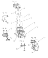
- the removal conveyor 30 with two parallel to the conveying plane oriented, rotationally drivable support rollers 31, on which adjacent to the glass blanks are provided.
- the linear conveyor Lifting device 1 At the lower end of the support rollers 31 is with the linear conveyor Lifting device 1 in alignment, one at the bottom of the glass blank attacking auxiliary conveyor 33 is provided.
- the auxiliary conveyor 33 is in the embodiment from an endless conveyor belt attacking the glass blank at the bottom 34 and just above this from the glass cut from the front and short endless conveyor belts 35, 36 attacking from behind an endless conveyor belt 36 (FIG. 6d) is pivotable Frame 37 mounted so that it is using a pressure medium cylinder 38 to the surface of the glass blank facing him can be created.
- the auxiliary conveyor 33 provides the Transport of a glass blank from the lifting device 1 in one of the compartments of the shelf 20 securely, even if it is are short glass cuts. In particular, the return transport of buffered glass blanks over the Lifting device 1 on the intermediate conveyor 10 in the final Sorting made easier.
- an intermediate conveyor 70 (Fig. 7) can be provided if this requires space make it seem useful.
- the conveying of a glass blank into a selected subject of the Buffer memory 20 or conveying a glass blank along the support wall 24 through the buffer memory 20 is through mounted in the base frame 21 of the shelf 20 by a Motor 42 supports drivable transport rollers 40.
- This Transport rollers 40 are on a common bar 41 mounted that they by pivoting the bar 41 in their Action raised when a glass blank is placed in a compartment of the Buffer memory 20 transported or through the buffer memory 20 is to be promoted. To adjust the carriage 21 of the buffer memory 20 can not hinder the transport rollers 40 are lowered from their active position.
- a further conveyor device 80 can be provided in the buffer store 20 be, whose lower support rollers can be driven, around glass blanks conveyed through the buffer memory 20 (Remnants, damaged blanks) continue to a collection pan 90 to transport for broken glass.
- the conveyor support wall 80 can with the help of a pressure cylinder be tipped forward to cut glass into the collection pan 90 dump.
- Fig. 7 is a plan view of a plant for sorting Glass blanks shown, the device according to the invention for sorting glass blanks. 7 is shown that the device 1 for erecting the lying advanced glass blanks next to the delivery end a glass cutting table 50 is arranged. on the one Side of the device 1 for erecting glass blanks the intermediate conveyor 10 is arranged which the glass blanks in one of the compartment trolleys 60 provided on its delivery side sorted according to any order criteria.
- the intermediate conveyor 70 On the opposite side of the intermediate conveyor 10 Device 1 for erecting glass panes is the intermediate conveyor 70 is provided, which can be similar like the intermediate conveyor 10. Following the intermediate conveyor 70, the removal conveyor 30 is provided, for example that shown in detail in Figs. 6 to 6d Construction. After this removal conveyor 30 is the buffer storage 20 designed as a shelf is provided. On the opposite side of the removal conveyor 30 Buffer memory 20, the conveyor 80 is provided whose support wall can be tilted forward so that on the Conveyor 80 standing and leaning against its support wall Glass blanks in the arranged in front of the conveyor 80 Collection tray 90 can be tilted.
- a sorting system for glass blanks is next to one Device 1 for erecting horizontally conveyed Glass blanks on the one conveyor 10, with the glass blanks in compartment trolleys 60, in which they are sorted are provided on the opposite side of a buffer memory 20.
- the buffer memory 20 is a shelf, the Compartments are formed by several tensioned ropes. By doing Buffer memory 20, glass blanks can be placed without hindering the rest of the sorting process.
- the fan-carrying carriage 21 of the buffer store 20 opposite its base frame 22 transversely to the conveying plane adjustable is the fan-carrying carriage 21 of the buffer store 20 opposite its base frame 22 transversely to the conveying plane adjustable.
- One of the compartments of the buffer memory 20 is one with rollers populated wall 24 assigned so that damaged blanks or unnecessary glass blanks (remnants) through the buffer storage 20 can be promoted in a collection pan 90.
- a removal conveyor 30 provided, the two almost vertically drivable Rollers 31 and one at the lower end thereof
Landscapes
- Re-Forming, After-Treatment, Cutting And Transporting Of Glass Products (AREA)
- Attitude Control For Articles On Conveyors (AREA)
- Sorting Of Articles (AREA)
- Warehouses Or Storage Devices (AREA)
- Glass Compositions (AREA)
- Intermediate Stations On Conveyors (AREA)
- Processing Of Stones Or Stones Resemblance Materials (AREA)
- Container, Conveyance, Adherence, Positioning, Of Wafer (AREA)
Abstract
Description
Die Erfindung betrifft eine Vorrichtung zum Sortieren von Glaszuschnitten, mit einer Hebeeinrichtung, um liegend herangeförderte Glaszuschnitte im wesentlichen lotrecht aufzurichten und mit einer Fördereinrichtung, durch welche aufgerichtete Glaszuschnitte nach beliebigen Ordnungskriterien Fächerwagen zugeführt und in diesen abgestellt werden.The invention relates to a device for sorting Glass blanks, with a lifting device, to be conveyed horizontally Almost erect glass blanks vertically and with a conveyor through which erect Glass cuts according to any order criteria Fan trolleys are fed and parked in these.
Eine derartige Vorrichtung ist aus der EP 477 163 A bekannt. Die bekannte Sortiervorrichtung, in der eine Vielzahl von Fächerwagen verwendet wird, wird bevorzugt im Zusammenhang mit einer Glasschneideanlage verwendet, wie sie beispielsweise aus der DE 43 05 826 A bekannt ist.Such a device is known from EP 477 163 A. The well-known sorting device in which a variety of Trolley used, is preferred in connection with a glass cutting machine used, such as from DE 43 05 826 A is known.
Problematisch bei den bekannten Sortiervorrichtungen ist es, daß das Aussortieren von nicht benötigten Glaszuschnitten (Reste) und beschädigter Glaszuschnitte eines Eingriffs von Hand aus bedarf. Weiters hat es sich als nachteilig erwiesen, daß sich manchmal Probleme ergeben, wenn es längere Zeit dauert, bis mehrere nach dem gewählten Ordnungskriterium zu einer bestimmten Gruppe gehörende Glaszuschnitte (z.B. die beiden Zuschnitte zum Herstellen einer Isolierglasscheibe) von der Glasschneideanlage zugeliefert werden.The problem with the known sorting devices is that that the sorting of unnecessary glass blanks (Remnants) and damaged glass blanks from an intervention by Hand out of need. Furthermore, it has proven to be disadvantageous that sometimes problems arise when it takes a long time up to several according to the selected order criteria glass cuts belonging to a certain group (e.g. the two Blanks for producing an insulating glass pane) from the Glass cutting system can be supplied.
Der Erfindung liegt die Aufgabe zugrunde, eine Vorrichtung zum Sortieren von Glaszuschnitten der eingangs genannten Gattung so zu verbessern, daß das Aussortieren nicht benötigter oder beschädigter Glaszuschnitte einfach möglich ist und daß zusätzliche Pufferkapazität vorliegt.The invention has for its object a device for Sorting glass blanks of the type mentioned at the beginning to improve so that the sorting not needed or damaged glass blanks is easily possible and that additional There is buffer capacity.
Erfindungsgemäß wird diese Aufgabe mit den Merkmalen des Anspruches
1 gelöst.According to the invention, this object is achieved with the features of the
Bevorzugte und vorteilhafte Ausgestaltungen der erfindungsgemäßen Glastafelzuschnittsortiervorrichtung sind Gegenstand der Unteransprüche.Preferred and advantageous embodiments of the invention Glass sheet blank sorting device are subject of subclaims.
Bei der erfindungsgemäßen Vorrichtung ist der Hebeeinrichtung zum Aufrichten der liegend herangeförderten Glaszuschnitte nicht wie aus der EP 477 163 A bekannt, nur auf einer Seite eine Fördereinrichtung zugeordnet, welche die Glaszuschnitte zu den Fächerwagen fördert, sondern dem anderen Ende der Hebeeinrichtung ist ein Pufferspeicher, z.B. in Form eines Fächerregals, zugeordnet. So wird Stauraum gewonnen, in dem, ohne den eigentlichen Sortiervorgang zu behindern, Glaszuschnitte warten können, bis der nächste Zuschnitt oder weitere Zuschnitte, die nach einem bestimmten Ordnungskriterium zu einer Gruppe von wenigstens zwei Glaszuschnitten gehören, herangefördert werden.In the device according to the invention is the lifting device for straightening up the glass blanks conveyed horizontally not as known from EP 477 163 A, only on one side a conveyor assigned to the glass blanks to the compartment trolley, but the other end of the lifting device is a buffer memory, e.g. in the form of a shelf, assigned. In this way, storage space is gained in which glass cuts without hindering the actual sorting process can wait for the next cut or more Cuts that according to a certain ordering criterion belong to a group of at least two glass blanks, be promoted.
Dieser Pufferspeicher erlaubt es auch, eines seiner Fächer als Einrichtung zum Durchfördern von Glaszuschnitten einzurichten, so daß beschädigte und/oder nicht benötigte Zuschnitte (Reste) in einen Sammelbehälter für nicht benötigte Glaszuschnitte oder beschädigtes Glas gefördert werden können.This buffer memory also allows one of its compartments to be used To set up equipment for conveying glass blanks, so that damaged and / or unnecessary blanks (remnants) in a collection container for glass cuts that are not required or damaged glass can be conveyed.
Weitere Einzelheiten und Merkmale der Erfindung ergeben sich aus der nachstehenden Beschreibung eines bevorzugten Ausführungsbeispieles der Erfindung, das insbesondere dazu geeignet ist, mit einer Glasschneideanlage kombiniert zu werden, wie sie beispielsweise aus der DE 43 05 826 A bekannt ist.Further details and features of the invention emerge from the following description of a preferred embodiment of the invention, particularly suitable for this is to be combined with a glass cutting machine, such as it is known for example from DE 43 05 826 A.
Es zeigt:
Einer in Fig. 1 gezeigten Einrichtung 1 (Hebeeinrichtung) zum
Aufrichten von in Richtung des Pfeiles 2 von einer Glasschneideanlage,
beispielsweise einer Glasschneideanlage 50 (Fig. 7)
der aus der DE 43 05 826 A bekannten Bauart, werden Glaszuschnitte
liegend zugeführt. Im Normalfall werden die Glaszuschnitte,
so wie dies aus der DE 43 05 826 A bekannt ist, nach
dem Aufrichten in Richtung des Pfeiles 3 in Fig. 1 auf einen
Zwischenförderer 10 bewegt. Der Zwischenförderer 10 weist an
seinem unteren Ende eine Fördereinrichtung, z.B. ein Förderband
11, auf, und ist in Richtung des Doppelpfeiles 12 auf und
ab verstellbar. Vom Zwischenförderer 10 werden die Glaszuschnitte,
so wie dies in der EP 477 163 A bekannt ist, in
Richtung des Pfeiles 3 in einen von mehreren Fächerwagen 60
(Fig. 7) transportiert oder sonst wie weiterverarbeitet. Dadurch,
daß der Zwischenförderer 10 höhenverstellbar ist, können
Glaszuschnitte, nachdem sie von der Einrichtung 1 auf den
Zwischenförderer 10 bewegt worden sind, soweit abgesenkt werden,
daß ihre untere horizontale Kante in der Höhe des unteren
Endes der Fächer in dem Fächerwagen 60 liegt.A device 1 (lifting device) shown in FIG. 1 for
Erecting in the direction of
Wie aus der Gesamtdarstellung von Fig. 1 ersichtlich, ist auf
der dem Zwischenförderer 10 gegenüberliegenden Seite neben der
Einrichtung 1 zum Aufrichten von Glaszuschnitten entweder
unmittelbar oder unter Zwischenschaltung eines Abtransportförderers
30 (sh. Fig. 6), dem ein weiterer Zwischenförderer 70
ähnlich dem Zwischenförderer 10, z.B. bestehend aus einer
Rollenstützwand und einem Horizontalförderer (Förderband oder
Rollenzeile) vorgeschaltet sein kann, ein Pufferspeicher 20
angeordnet. Dieser Pufferspeicher 20 ist im Ausführungsbeispiel
als Fächerregal ausgebildet. Der Pufferspeicher 20 besitzt
einen Wagen 21, der auf einem Untergestell 22 in Richtung
des Doppelpfeiles 23 verschiebbar ist. In dem Wagen 21
sind durch gespannte Seile (vorzugsweise bestückt mit Hülsen
gemäß der EP 477 163 A) gebildete Fächer (der Übersichtlichkeit
wegen sind nur einzelne Teile gezeigt) vorgesehen. Ein
Fach, z.B. das erste Fach weist eine mit Rollen bestückte
Stützwand 24 auf und ist so als Fach zum Durchfördern von
Glaszuschnitten durch den Pufferspeicher 20 ausgebildet ist.As can be seen from the overall illustration in FIG. 1, is on
the side opposite the
Der Wagen 21 ist gegenüber seinem Untergestell 22, wie erwähnt,
verschiebbar, um das jeweils gewünschte Fach gegenüber
der Förderebene der Einrichtung 1 bzw. des Abtransportförderers
30 auszurichten, so daß ein Glaszuschnitt in ein ausgewähltes
Fach des Pufferspeichers 20 transportiert und in dem
als Pufferspeicher 20 dienenden Fächerregal abgestellt werden
kann.The
Zum Verstellen des Wagens 21 des Pufferspeichers 20 gegenüber
seinem Untergestell 22 ist der Wagen 21 auf Gleitschuhen 27
(Fig. 5) an Führungsschienen 25 geführt, wobei zum Antrieb ein
Antriebsmotor 26 vorgesehen ist, der mit einem (oder zwei)
Ritzel in eine (oder zwei) am Wagen 21 montierte Zahnstange
eingreift.To adjust the
Zwischen der Hebeeinrichtung 1 und dem Pufferspeicher 20 ist
der Abtransportförderer 30 mit zwei zur Förderebene parallel
orientierten, drehantreibbaren Stützwalzen 31, an welchen
anliegend die Glaszuschnitte bewegt werden, vorgesehen. Am
unteren Ende der Stützwalzen 31 ist mit dem Linearförderer der
Hebeeinrichtung 1 fluchtend, eine am unteren Rand des Glaszuschnittes
angreifende Hilfsfördereinrichtung 33 vorgesehen.
Die Hilfsfördereinrichtung 33 besteht im Ausführungsbeispiel
aus einem am Glaszuschnitt unten angreifenden Endlosförderband
34 und knapp ober diesem aus am Glaszuschnitt von vorne und
von hinten angreifenden kurzen Endlosförderbändern 35, 36. Das
eine Endlosförderband 36 (Fig. 6d) ist an einem verschwenkbaren
Rahmen 37 montiert, so daß es mit Hilfe eines Druckmittelzylinders
38 an die ihm zugekehrte Fläche des Glaszuschnittes
angelegt werden kann. Der Hilfsförderer 33 stellt den
Transport eines Glaszuschnittes von der Hebeeinrichtung 1 in
eines der Fächer des Fächerregals 20 sicher, auch wenn es sich
um kurze Glaszuschnitte handelt. Insbesondere wird der Rücktransport
von zwischengespeicherten Glaszuschnitten über die
Hebeeinrichtung 1 auf den Zwischenförderer 10 beim endgültigen
Sortieren erleichtert.Is between the
Wie erwähnt, kann zwischen der Hebeeinrichtung 1 und dem Abtransportförderer
30 mit den Stützwalzen 31 ein Zwischenförderer
70 (Fig. 7) vorgesehen sein, wenn dies räumliche Erfordernisse
zweckdienlich erscheinen lassen.As mentioned, can be between the
Das Fördern eines Glaszuschnitten in ein ausgewähltes Fach des
Pufferspeichers 20 oder das Fördern eines Glaszuschnittes entlang
der Stützwand 24 durch den Pufferspeicher 20 wird durch
im Grundgestell 21 des Fächerregals 20 montierte, durch einen
Motor 42 antreibbare Transportrollen 40 unterstützt. Diese
Transportrollen 40 sind an einem gemeinsamen Balken 41 derart
montiert, daß sie durch Verschwenken des Balkens 41 in ihre
Wirklage angehoben, wenn ein Glaszuschnitt in ein Fach des
Pufferspeichers 20 transportiert oder durch den Pufferspeicher
20 durchgefördert werden soll. Um das Verstellen des Wagens 21
des Pufferspeichers 20 nicht zu behindern, können die Transportrollen
40 aus ihrer Wirklage abgesenkt werden.The conveying of a glass blank into a selected subject of the
Auslaufseitig der Stützwand 24 an einem Ende des Wagens 21 des
Pufferspeichers 20 kann eine weitere Fördereinrichtung 80 vorgesehen
sein, deren untere Stützrollen angetrieben sein können,
um durch den Pufferspeicher 20 geförderte Glaszuschnitte
(Reste, beschädigte Zuschnitte) weiter bis zu einer Sammelwanne
90 für Glasbruch zu transportieren. Die Stützwand der Fördereinrichtung
80 kann mit Hilfe eines Druckmittelzylinders
nach vorne gekippt werden, um Glaszuschnitte in die Sammelwanne
90 abzukippen.On the outlet side of the
In Fig. 7 ist in Draufsicht eine Anlage zum Sortieren von
Glaszuschnitten gezeigt, welche die erfindungsgemäße Einrichtung
zum Sortieren von Glaszuschnitten enthält. In Fig. 7 ist
gezeigt, daß die Einrichtung 1 zum Aufrichten der liegend
herangeförderten Glaszuschnitte neben dem abgabeseitigen Ende
eines Glasschneidetisches 50 angeordnet ist. Auf der einen
Seite der Einrichtung 1 zum Aufrichten von Glaszuschnitten ist
der Zwischenförderer 10 angeordnet, der die Glaszuschnitte in
einen der an seiner Abgabeseite bereitgestellte Fächerwagen 60
nach beliebigen Ordnungskriterien sortiert abstellt.In Fig. 7 is a plan view of a plant for sorting
Glass blanks shown, the device according to the invention
for sorting glass blanks. 7 is
shown that the
Auf der dem Zwischenförderer 10 gegenüberliegenden Seite der
Einrichtung 1 zum Aufrichten von Glasscheiben ist der Zwischenförderer
70 vorgesehen, der ähnlich ausgebildet sein kann
wie der Zwischenförderer 10. Im Anschluß an den Zwischenförderer
70 ist der Abtransportförderer 30 vorgesehen, der beispielsweise
die in Einzelheiten in Fig. 6 bis 6d gezeigte
Konstruktion besitzt. Nach diesem Abtransportförderer 30 ist
der als Fächerregal ausgebildete Pufferspeicher 20 vorgesehen.
Auf der dem Abtransportförderer 30 gegenüberliegende Seite des
Pufferspeichers 20 ist die Fördereinrichtung 80 vorgesehen,
deren Stützwand nach vorne gekippt werden kann, so daß auf der
Fördereinrichtung 80 stehende und an ihrer Stützwand lehnende
Glaszuschnitte in die vor der Fördereinrichtung 80 angeordnete
Sammelwanne 90 abgekippt werden können.On the opposite side of the
Zusammenfassend kann ein Ausführungsbeispiel der Erfindung wie folgt dargestellt werden:In summary, an embodiment of the invention can be like are represented as follows:
Bei einer Sortieranlage für Glaszuschnitte ist neben einer
Einrichtung 1 zum Aufrichten von liegend herangeförderten
Glaszuschnitten auf der einem Förderer 10, mit dem Glaszuschnitte
in Fächerwagen 60, in welchen sie sortiert abgestellt
werden, gegenüberliegenden Seite ein Pufferspeicher 20 vorgesehen.
Der Pufferspeicher 20 ist ein Fächerregal, dessen
Fächer von mehreren gespannten Seilen gebildet werden. In dem
Pufferspeicher 20 können Glaszuschnitte abgestellt werden,
ohne den übrigen Sortiervorgang zu behindern. Um die Fächer
des Fächerregals des Pufferspeichers 20 gegenüber der Förderebene
der Einrichtung 1 zum Aufstellen von Glaszuschnitten
auszurichten, ist der Fächer aufweisende Wagen 21 des Pufferspeichers
20 gegenüber seinem Grundgestell 22 quer zur Förderebene
verstellbar.In a sorting system for glass blanks is next to one
Einem der Fächer des Pufferspeichers 20 ist eine mit Rollen
bestückte Wand 24 zugeordnet, so daß beschädigte Zuschnitte
oder nicht benötigte Glaszuschnitte (Reste) durch den Pufferspeicher
20 in eine Sammelwanne 90 gefördert werden können.
Um den sicheren Transport von Glaszuschnitten aus die Einrichtung
1 zum Aufrichten von Glaszuschnitten in den Pufferspeicher
20 zu gewährleisten, auch wenn es sich um kleine Zuschnitte
handelt, ist zwischen der Einrichtung 1 zum Aufrichten
von Glaszuschnitten und dem Pufferspeicher 20 ein Abtransportförderer
30 vorgesehen, der zwei annähernd lotrechte drehantreibbare
Walzen 31 und am unteren Ende derselben einen
Hilfsförderer 33 mit zwei an den Flächen des Glaszuschnittes
angreifenden und einem am unteren Rand des Glaszuschnittes
angreifenden Fördermitteln aufweist, vorgesehen.One of the compartments of the
Claims (14)
Applications Claiming Priority (3)
| Application Number | Priority Date | Filing Date | Title |
|---|---|---|---|
| AT1178/96 | 1996-07-03 | ||
| AT117896 | 1996-07-03 | ||
| AT0117896A AT405618B (en) | 1996-07-03 | 1996-07-03 | DEVICE FOR SORTING GLASS PANEL CUTS |
Publications (3)
| Publication Number | Publication Date |
|---|---|
| EP0816265A2 true EP0816265A2 (en) | 1998-01-07 |
| EP0816265A3 EP0816265A3 (en) | 1998-03-04 |
| EP0816265B1 EP0816265B1 (en) | 2001-08-22 |
Family
ID=3508304
Family Applications (1)
| Application Number | Title | Priority Date | Filing Date |
|---|---|---|---|
| EP97890115A Expired - Lifetime EP0816265B1 (en) | 1996-07-03 | 1997-07-01 | Apparatus for sorting cut sheets of glass |
Country Status (6)
| Country | Link |
|---|---|
| US (1) | US6077018A (en) |
| EP (1) | EP0816265B1 (en) |
| AT (2) | AT405618B (en) |
| DE (3) | DE29711484U1 (en) |
| ES (1) | ES2161435T3 (en) |
| IT (1) | IT237634Y1 (en) |
Cited By (6)
| Publication number | Priority date | Publication date | Assignee | Title |
|---|---|---|---|---|
| EP1588962A1 (en) * | 2004-04-23 | 2005-10-26 | HEGLA Fahrzeug- u. Maschinenbau GmbH & Co. KG | Loading mechanism for loading sheet-like material in a sorted manner into a storage device |
| CN102275706A (en) * | 2011-05-10 | 2011-12-14 | 江苏迅捷装具科技有限公司 | Horizontal-moving movable frame delivery device |
| CN103662377A (en) * | 2012-08-31 | 2014-03-26 | 昆山冠益玻璃有限公司 | Glass transportation frame, |
| RU2512870C1 (en) * | 2009-10-22 | 2014-04-10 | Инова Лисец Технологицентрум Гмбх | Method and device to lay distancing tapes onto window glasses |
| US9682812B2 (en) | 2013-01-28 | 2017-06-20 | Lisec Austria Gmbh | Device having pivotable compartments |
| DE102017005809B4 (en) | 2017-06-20 | 2019-07-18 | Grenzebach Maschinenbau Gmbh | Device and method for the safe and quick transfer of new glass plates from the production line to a transport vehicle |
Families Citing this family (10)
| Publication number | Priority date | Publication date | Assignee | Title |
|---|---|---|---|---|
| DE10164071A1 (en) | 2001-12-24 | 2003-07-03 | Hegla Fahrzeug Und Maschb Gmbh | Method and device for sorting glass sheets |
| DE20216438U1 (en) * | 2002-10-24 | 2004-03-04 | Lisec, Peter | Glass cutting system with intermediate storage |
| JP5792936B2 (en) * | 2010-08-27 | 2015-10-14 | 川崎重工業株式会社 | Plate member transfer equipment |
| US9004839B2 (en) * | 2011-10-18 | 2015-04-14 | Shenzhen China Star Optoelectronics Technology Co., Ltd. | Glass substrate storage and transportation system and a glass substrate storage platform |
| ITTO20120903A1 (en) | 2012-10-16 | 2014-04-17 | Biesse Spa | MACHINE TO CARRY OUT THE CUTTING OF A LAMINATED GLASS SHEET WITH A WAITING SECTION EQUIPPED WITH MEANS OF TRANSPORT |
| US9951553B2 (en) | 2014-06-05 | 2018-04-24 | Erdman Automation Corporation | High speed parallel process insulated glass manufacturing line |
| US10253552B2 (en) | 2016-04-21 | 2019-04-09 | Erdman Automation Corporation | High speed parallel process insulated glass manufacturing line |
| US10336528B2 (en) * | 2016-12-30 | 2019-07-02 | Guardian Glass, LLC | Rail car rack |
| IT201700071422A1 (en) * | 2017-06-27 | 2018-12-27 | Forel Spa | AUTOMATIC SYSTEM AND AUTOMATIC PROCEDURE FOR MANUFACTURING WITH HIGH PRODUCTIVITY OF THE INSULATING GLASS CONSISTING OF AT LEAST TWO GLASS SHEETS AND AT LEAST ONE SPACER FRAME |
| CN109967385B (en) * | 2019-04-08 | 2021-05-28 | 上海维誉自动化设备有限公司 | Automobile front windshield ISRA detection transmission line |
Citations (4)
| Publication number | Priority date | Publication date | Assignee | Title |
|---|---|---|---|---|
| EP0048334B1 (en) * | 1980-09-24 | 1984-03-07 | Bystronic Maschinen AG | Apparatus for sorting unsorted glass plates of a glass-cutting installation |
| EP0477163A1 (en) * | 1990-09-18 | 1992-03-25 | Peter Lisec | Device for sorting sized glass sheets |
| DE4305826A1 (en) * | 1992-04-06 | 1993-10-07 | Peter Lisec | Glass sheet division - has longitudinal and material scored lines with units to twist off edge strips with lower counter surfaces and upper retainers |
| WO1995025688A1 (en) * | 1994-03-24 | 1995-09-28 | Peter Lisec | Method and device for sorting blanks |
Family Cites Families (4)
| Publication number | Priority date | Publication date | Assignee | Title |
|---|---|---|---|---|
| FR2279071A1 (en) * | 1974-07-19 | 1976-02-13 | Saint Gobain | INSTALLATION OF AUTOMATIC CONTROL OF THE CURVATURE OF BOMB WINDOWS |
| AT387765B (en) * | 1987-06-09 | 1989-03-10 | Lisec Peter | DEVICE FOR HANDLING SPACER FRAME |
| AT396782B (en) * | 1991-12-23 | 1993-11-25 | Lisec Peter | DEVICE FOR PROMOTING INSULATED GLASS PANELS INCLUDING SOMETHING RIGHT |
| DE59306676D1 (en) * | 1993-04-14 | 1997-07-10 | Bystronic Masch | Plant for sorting sheet material |
-
1996
- 1996-07-03 AT AT0117896A patent/AT405618B/en not_active IP Right Cessation
-
1997
- 1997-07-01 DE DE29711484U patent/DE29711484U1/en not_active Expired - Lifetime
- 1997-07-01 DE DE59704355T patent/DE59704355D1/en not_active Expired - Lifetime
- 1997-07-01 DE DE19728044A patent/DE19728044C2/en not_active Expired - Fee Related
- 1997-07-01 ES ES97890115T patent/ES2161435T3/en not_active Expired - Lifetime
- 1997-07-01 AT AT97890115T patent/ATE204552T1/en active
- 1997-07-01 EP EP97890115A patent/EP0816265B1/en not_active Expired - Lifetime
- 1997-07-02 IT IT1997MI000487U patent/IT237634Y1/en active IP Right Grant
- 1997-07-03 US US08/888,093 patent/US6077018A/en not_active Expired - Lifetime
Patent Citations (4)
| Publication number | Priority date | Publication date | Assignee | Title |
|---|---|---|---|---|
| EP0048334B1 (en) * | 1980-09-24 | 1984-03-07 | Bystronic Maschinen AG | Apparatus for sorting unsorted glass plates of a glass-cutting installation |
| EP0477163A1 (en) * | 1990-09-18 | 1992-03-25 | Peter Lisec | Device for sorting sized glass sheets |
| DE4305826A1 (en) * | 1992-04-06 | 1993-10-07 | Peter Lisec | Glass sheet division - has longitudinal and material scored lines with units to twist off edge strips with lower counter surfaces and upper retainers |
| WO1995025688A1 (en) * | 1994-03-24 | 1995-09-28 | Peter Lisec | Method and device for sorting blanks |
Cited By (8)
| Publication number | Priority date | Publication date | Assignee | Title |
|---|---|---|---|---|
| EP1588962A1 (en) * | 2004-04-23 | 2005-10-26 | HEGLA Fahrzeug- u. Maschinenbau GmbH & Co. KG | Loading mechanism for loading sheet-like material in a sorted manner into a storage device |
| RU2512870C1 (en) * | 2009-10-22 | 2014-04-10 | Инова Лисец Технологицентрум Гмбх | Method and device to lay distancing tapes onto window glasses |
| US8758532B2 (en) | 2009-10-22 | 2014-06-24 | Inova Lisec Technologiezentrum Gmbh | Device and method for applying spacer tapes to glass panes |
| CN102275706A (en) * | 2011-05-10 | 2011-12-14 | 江苏迅捷装具科技有限公司 | Horizontal-moving movable frame delivery device |
| CN102275706B (en) * | 2011-05-10 | 2013-01-02 | 江苏迅捷装具科技有限公司 | Horizontal-moving movable frame delivery device |
| CN103662377A (en) * | 2012-08-31 | 2014-03-26 | 昆山冠益玻璃有限公司 | Glass transportation frame, |
| US9682812B2 (en) | 2013-01-28 | 2017-06-20 | Lisec Austria Gmbh | Device having pivotable compartments |
| DE102017005809B4 (en) | 2017-06-20 | 2019-07-18 | Grenzebach Maschinenbau Gmbh | Device and method for the safe and quick transfer of new glass plates from the production line to a transport vehicle |
Also Published As
| Publication number | Publication date |
|---|---|
| IT237634Y1 (en) | 2000-09-13 |
| DE29711484U1 (en) | 1997-08-28 |
| EP0816265A3 (en) | 1998-03-04 |
| ITMI970487V0 (en) | 1997-07-02 |
| AT405618B (en) | 1999-10-25 |
| EP0816265B1 (en) | 2001-08-22 |
| ATA117896A (en) | 1999-02-15 |
| ITMI970487U1 (en) | 1999-01-02 |
| DE59704355D1 (en) | 2001-09-27 |
| US6077018A (en) | 2000-06-20 |
| ATE204552T1 (en) | 2001-09-15 |
| DE19728044A1 (en) | 1998-01-08 |
| DE19728044C2 (en) | 2001-03-08 |
| ES2161435T3 (en) | 2001-12-01 |
Similar Documents
| Publication | Publication Date | Title |
|---|---|---|
| EP0477163B1 (en) | Device for sorting sized glass sheets | |
| EP0816265B1 (en) | Apparatus for sorting cut sheets of glass | |
| EP1434744B1 (en) | Method and device for moving and positioning glass plates | |
| AT401172B (en) | METHOD FOR DIVIDING GLASS PANELS INTO CUTS | |
| EP0675060B1 (en) | Apparatus for stacking and destacking sheet shaped objects | |
| EP0564758B1 (en) | Method and apparatus for dividing glass sheets into parts | |
| WO2005066046A1 (en) | Picking station | |
| EP0708741B1 (en) | Device for splitting multilayer glass | |
| WO2004048284A1 (en) | Device and method for displacing glass plates during the machining of the same | |
| EP1492734B1 (en) | Device and method for dividing vertical glass plates | |
| DE19519093C2 (en) | Arrangement for splitting laminated glass with a device for splitting laminated glass and a glass cutting table | |
| DE2702724C2 (en) | Device for sorting and storing blanks in panel dividing systems | |
| AT402194B (en) | METHOD AND SYSTEM FOR SORTING CUTS | |
| EP1284229B3 (en) | Process and apparatus for handling glass sheets | |
| DE19600348A1 (en) | Shelving system with vertical compartments for sheets or panels e.g. for kitchen furniture and chip-board industry | |
| DE2645232A1 (en) | Vertical buffer frame linked to horizontal plate conveyor - is controlled by two pairs of plate sensors which overlap conveyor belts | |
| EP1588962B1 (en) | Loading mechanism for loading sheet-like material in a sorted manner into a storage device | |
| EP0321685A2 (en) | Method for supporting beams | |
| DE10026346A1 (en) | Vertical conveyor | |
| EP1655248B1 (en) | Driving mechanism for a series of free rollers or for free conveyor belts | |
| DE3345940A1 (en) | Device for manipulating panes of glass used in double glazing | |
| EP0691311A1 (en) | Apparatus for cutting laminated glass | |
| DE2539352A1 (en) | Mechanical handling of glass panes - during mass prodn. of panes and distance pieces for double glazing | |
| DE20220733U1 (en) | Production of glass panes, cut from a pattern of pane outlines on glass sheets, has an intermediate store for uncut glass sheet residue to be selected for marking in further cutting cycles | |
| DE19801692A1 (en) | Glass panel etc. transfer procedure |
Legal Events
| Date | Code | Title | Description |
|---|---|---|---|
| PUAI | Public reference made under article 153(3) epc to a published international application that has entered the european phase |
Free format text: ORIGINAL CODE: 0009012 |
|
| AK | Designated contracting states |
Kind code of ref document: A2 Designated state(s): AT CH DE ES FR GB IT LI SE |
|
| PUAL | Search report despatched |
Free format text: ORIGINAL CODE: 0009013 |
|
| AK | Designated contracting states |
Kind code of ref document: A3 Designated state(s): AT BE CH DE DK ES FI FR GB GR IE IT LI LU MC NL PT SE |
|
| 17P | Request for examination filed |
Effective date: 19980210 |
|
| AKX | Designation fees paid |
Free format text: AT CH DE ES FR GB IT LI SE |
|
| RBV | Designated contracting states (corrected) |
Designated state(s): AT CH DE ES FR GB IT LI SE |
|
| 17Q | First examination report despatched |
Effective date: 19991220 |
|
| GRAG | Despatch of communication of intention to grant |
Free format text: ORIGINAL CODE: EPIDOS AGRA |
|
| GRAG | Despatch of communication of intention to grant |
Free format text: ORIGINAL CODE: EPIDOS AGRA |
|
| GRAH | Despatch of communication of intention to grant a patent |
Free format text: ORIGINAL CODE: EPIDOS IGRA |
|
| GRAH | Despatch of communication of intention to grant a patent |
Free format text: ORIGINAL CODE: EPIDOS IGRA |
|
| GRAA | (expected) grant |
Free format text: ORIGINAL CODE: 0009210 |
|
| AK | Designated contracting states |
Kind code of ref document: B1 Designated state(s): AT CH DE ES FR GB IT LI SE |
|
| REF | Corresponds to: |
Ref document number: 204552 Country of ref document: AT Date of ref document: 20010915 Kind code of ref document: T |
|
| REG | Reference to a national code |
Ref country code: CH Ref legal event code: NV Representative=s name: TROESCH SCHEIDEGGER WERNER AG Ref country code: CH Ref legal event code: EP |
|
| REF | Corresponds to: |
Ref document number: 59704355 Country of ref document: DE Date of ref document: 20010927 |
|
| ET | Fr: translation filed | ||
| REG | Reference to a national code |
Ref country code: ES Ref legal event code: FG2A Ref document number: 2161435 Country of ref document: ES Kind code of ref document: T3 |
|
| GBT | Gb: translation of ep patent filed (gb section 77(6)(a)/1977) |
Effective date: 20011116 |
|
| REG | Reference to a national code |
Ref country code: GB Ref legal event code: IF02 |
|
| PLBE | No opposition filed within time limit |
Free format text: ORIGINAL CODE: 0009261 |
|
| STAA | Information on the status of an ep patent application or granted ep patent |
Free format text: STATUS: NO OPPOSITION FILED WITHIN TIME LIMIT |
|
| 26N | No opposition filed | ||
| REG | Reference to a national code |
Ref country code: GB Ref legal event code: 732E |
|
| REG | Reference to a national code |
Ref country code: FR Ref legal event code: TP |
|
| REG | Reference to a national code |
Ref country code: DE Ref legal event code: R082 Ref document number: 59704355 Country of ref document: DE Representative=s name: PATENTANWAELTE HENKEL, BREUER & PARTNER, DE |
|
| REG | Reference to a national code |
Ref country code: FR Ref legal event code: PLFP Year of fee payment: 20 |
|
| PGFP | Annual fee paid to national office [announced via postgrant information from national office to epo] |
Ref country code: GB Payment date: 20160721 Year of fee payment: 20 Ref country code: IT Payment date: 20160725 Year of fee payment: 20 Ref country code: CH Payment date: 20160721 Year of fee payment: 20 Ref country code: DE Payment date: 20160722 Year of fee payment: 20 |
|
| PGFP | Annual fee paid to national office [announced via postgrant information from national office to epo] |
Ref country code: FR Payment date: 20160721 Year of fee payment: 20 Ref country code: AT Payment date: 20160728 Year of fee payment: 20 Ref country code: SE Payment date: 20160720 Year of fee payment: 20 |
|
| PGFP | Annual fee paid to national office [announced via postgrant information from national office to epo] |
Ref country code: ES Payment date: 20160715 Year of fee payment: 20 |
|
| REG | Reference to a national code |
Ref country code: DE Ref legal event code: R071 Ref document number: 59704355 Country of ref document: DE |
|
| REG | Reference to a national code |
Ref country code: CH Ref legal event code: PL |
|
| REG | Reference to a national code |
Ref country code: GB Ref legal event code: PE20 Expiry date: 20170630 |
|
| PG25 | Lapsed in a contracting state [announced via postgrant information from national office to epo] |
Ref country code: GB Free format text: LAPSE BECAUSE OF EXPIRATION OF PROTECTION Effective date: 20170630 |
|
| REG | Reference to a national code |
Ref country code: AT Ref legal event code: MK07 Ref document number: 204552 Country of ref document: AT Kind code of ref document: T Effective date: 20170701 |
|
| REG | Reference to a national code |
Ref country code: ES Ref legal event code: FD2A Effective date: 20180508 |
|
| PG25 | Lapsed in a contracting state [announced via postgrant information from national office to epo] |
Ref country code: ES Free format text: LAPSE BECAUSE OF EXPIRATION OF PROTECTION Effective date: 20170702 |