EP0816167B1 - Aiming mechanism for vehicle lamps - Google Patents
Aiming mechanism for vehicle lamps Download PDFInfo
- Publication number
- EP0816167B1 EP0816167B1 EP97304679A EP97304679A EP0816167B1 EP 0816167 B1 EP0816167 B1 EP 0816167B1 EP 97304679 A EP97304679 A EP 97304679A EP 97304679 A EP97304679 A EP 97304679A EP 0816167 B1 EP0816167 B1 EP 0816167B1
- Authority
- EP
- European Patent Office
- Prior art keywords
- ball
- socket
- aiming
- socket member
- vehicle lamp
- Prior art date
- Legal status (The legal status is an assumption and is not a legal conclusion. Google has not performed a legal analysis and makes no representation as to the accuracy of the status listed.)
- Expired - Lifetime
Links
- 230000007246 mechanism Effects 0.000 title claims description 21
- 230000033001 locomotion Effects 0.000 claims description 7
- 238000006073 displacement reaction Methods 0.000 description 9
- 238000010276 construction Methods 0.000 description 5
- 210000002105 tongue Anatomy 0.000 description 3
- 229930182556 Polyacetal Natural products 0.000 description 2
- 229920006351 engineering plastic Polymers 0.000 description 2
- 238000003780 insertion Methods 0.000 description 2
- 230000037431 insertion Effects 0.000 description 2
- 238000000465 moulding Methods 0.000 description 2
- 229920006324 polyoxymethylene Polymers 0.000 description 2
- 229920002292 Nylon 6 Polymers 0.000 description 1
- -1 for example Polymers 0.000 description 1
- 239000000463 material Substances 0.000 description 1
- 238000000034 method Methods 0.000 description 1
- 229920003023 plastic Polymers 0.000 description 1
- 239000004033 plastic Substances 0.000 description 1
- 239000012858 resilient material Substances 0.000 description 1
- 238000006467 substitution reaction Methods 0.000 description 1
- 229920003002 synthetic resin Polymers 0.000 description 1
- 239000000057 synthetic resin Substances 0.000 description 1
Images




Classifications
-
- B—PERFORMING OPERATIONS; TRANSPORTING
- B60—VEHICLES IN GENERAL
- B60Q—ARRANGEMENT OF SIGNALLING OR LIGHTING DEVICES, THE MOUNTING OR SUPPORTING THEREOF OR CIRCUITS THEREFOR, FOR VEHICLES IN GENERAL
- B60Q1/00—Arrangement of optical signalling or lighting devices, the mounting or supporting thereof or circuits therefor
- B60Q1/02—Arrangement of optical signalling or lighting devices, the mounting or supporting thereof or circuits therefor the devices being primarily intended to illuminate the way ahead or to illuminate other areas of way or environments
- B60Q1/04—Arrangement of optical signalling or lighting devices, the mounting or supporting thereof or circuits therefor the devices being primarily intended to illuminate the way ahead or to illuminate other areas of way or environments the devices being headlights
- B60Q1/06—Arrangement of optical signalling or lighting devices, the mounting or supporting thereof or circuits therefor the devices being primarily intended to illuminate the way ahead or to illuminate other areas of way or environments the devices being headlights adjustable, e.g. remotely-controlled from inside vehicle
- B60Q1/068—Arrangement of optical signalling or lighting devices, the mounting or supporting thereof or circuits therefor the devices being primarily intended to illuminate the way ahead or to illuminate other areas of way or environments the devices being headlights adjustable, e.g. remotely-controlled from inside vehicle by mechanical means
- B60Q1/0683—Adjustable by rotation of a screw
-
- B—PERFORMING OPERATIONS; TRANSPORTING
- B60—VEHICLES IN GENERAL
- B60Q—ARRANGEMENT OF SIGNALLING OR LIGHTING DEVICES, THE MOUNTING OR SUPPORTING THEREOF OR CIRCUITS THEREFOR, FOR VEHICLES IN GENERAL
- B60Q2200/00—Special features or arrangements of vehicle headlamps
- B60Q2200/30—Special arrangements for adjusting headlamps, e.g. means for transmitting the movements for adjusting the lamps
- B60Q2200/32—Ball-joints
Definitions
- This invention relates generally to electric lamps, and particularly to those for use on motor vehicles such as, typically, headlamps. Still more particularly, the invention pertains to improvements in or relating to aiming mechanisms for aiming and retaining the beams of headlamps or the like in proper angular positions with respect to the vehicle.
- Aimable headlamps may be divided into two broad categories according to the member to be tilted, both vertically and horizontally, for aiming the beam.
- the complete headlamp unit comprising an electric lighting bulb or bulbs, a reflector or reflectors and a lens, is tilted relative to the vehicle or to the lamp housing fixed to the vehicle.
- the other design is such that only the reflector is tilted relative to the lamp body or the like which is fixed to the vehicle, for example, as shown in GB-A-2285307 (preamble of claim 1).
- a typical aiming mechanism comprises a pivotal connection such as a ball-and-socket joint between a tiltable member and a fixed member, and two aiming screws extending between the two members.
- the relative placement of the pivotal connection and the aiming screws is such that the first of the two aiming screws is displaced horizontally, and the second vertically, from the pivotal connection.
- the tightening or loosening of the first aiming screw results, therefore, in the tilting of the tiltable member about a vertical axis passing through the pivotal connection and the second aiming screw.
- the manipulation of the second aiming screw results in the tilting of the tiltable member about a horizontal axis passing through the pivotal connection and the first aiming screw.
- each aiming screw was rotatably supported by the fixed member and screw-threadedly engaged with a nut affixed to the tiltable member.
- the nut engaged therewith bad to travel arcuately with the tiltable member about either of the two axes but was nevertheless constrained to rectilinear displacement on the aiming screw.
- the resulting conflict between the circular and the linear motions impeded the smooth tilting of the tiltable member.
- the present invention seeks, in an aimable vehicle lamp of the kind defined, to realize smoother tilting motions of the tiltable member relative to the fixed member in aiming the lamp.
- the invention consists in an aiming mechanism for a vehicle lamp wherein the aiming mechanism is able to tilt a tiltable member of the vehicle lamp relative to a fixed member of the vehicle lamp in either of two orthogonal tilting directions, the aiming mechanism comprising:
- the nut that has conventionally been affixed to the tiltable member is replaced according to the invention by the ball rotatably received in the socket member secured to the tiltable member.
- the socket member on the tiltable member is free to undergo angular displacement on the ball thereby affording smoother tilting of the tiltable member than heretofore.
- the socket member which is molded from a resilient material into a substantially tubular shape, is formed to include at least a pair of detents in diametrically opposite positions on one end thereof. Projecting into the hollow in the socket member for rotatably retaining the ball in the socket, the detents are angled toward each other as they extend from said one end of the socket member toward the other. The ball may therefore be forced through the space between the pair of detents into the socket in the socket member, causing the detents to resiliently spread apart in so doing. Once the ball is positioned in the socket, the detents will posltively engage the ball to lock the same against detachment from within the socket member.
- the ball is formed to include a pair of flaring guide wings adjacent one end of the hole extending therethrough.
- the guide wings are intended to smoothly guide the aiming screw into threaded engagement in the hole in the ball.
- the tiltable member is tilted in one of the orthogonal directions by the aiming mechanism of the foregoing construction, and in the other direction by a leveling actuator.
- the leveling actuator Mounted to the fixed member, the leveling actuator has a connecting rod extending therefrom and terminating in a ball which is rotatably received in a socket member on the tiltable member.
- this socket member associated with the leveling actuator has formed therein an undercut groove extending vertically for rotatably engaging the ball on the connecting rod.
- FIG. 1 which illustrates the representative aimable headlamp insofar as is necessary for the full understanding of the invention
- a reflector 1 the tiltable member
- a lamp housing 2 the fixed member
- leveling actuator means including a leveling actuator 6, and two aiming screw means of identical make, each including an aiming screw 17.
- the lamp housing 2 is shown fragmentarily and in phantom outline because of illustrative convenience and of its conventional and well known nature.
- the two aiming screw means are shown horizontally spaced from each other, and the leveling actuator means shown spaced downwardly from one of the aiming screw means.
- the aiming screw means just above the leveling actuator means could be replaced by a simple universal connection between the tiltable and fixed members, as in an alternate embodiment of this invention to be disclosed subsequently.
- the provision of the two aiming screw means, in addition to the leveling actuator means, should not therefore be taken as an essential feature of this invention.
- the reflector 1 has a concave reflective surface which is conventionally rendered reflective to reflect the light from a light source such as a discharge bulb, not shown, forwardly of the vehicle.
- a light source such as a discharge bulb, not shown, forwardly of the vehicle.
- Three hollow bosses 3 c , 3 s and 3 d are formed on the back of the reflector 1 for connection to the leveling actuator means and the aiming screw means.
- the leveling actuator 6 has an actuator body 7 which is mounted fast to the lamp housing 2, and a connecting rod 8 projecting forwardly from the actuator body.
- the connecting rod 8 terminates in a ball 9 for pivotal engagement in a socket member 10 which in turn is to be immovably engaged in the boss 3 d on the back of the reflector 1.
- the socket member 10 is a one-piecenolding of a synthetic resin such as, for example, polyacetal, the molding including a socket portion 11 and a self-locking, snap-on connector portion 12.
- the socket portion 11 defines an elongate socket 13 which may be described as an undereut groove extending along the vertical axis about which is reflector 1 is to be pivoted horizontally by one of the aiming screw means.
- the self-locking, snap-on connector portion 12 of the socket member 10 is in the shape of a tube of rectangular cross section, sized to fit in the hollow boss 3 d on the reflector 1 through an opening 5 d in its rear wall 4 d .
- a pair of opposite side walls of the connector portion 12 have U-shaped slits formed therein to provide a pair of locking pawls 15 which grow thicker as they extend toward their free ends directed toward the leveling actuator 6, terminating in ledges 15 a .
- a pair of flanges 16 are formed just rearwardly of the ledges 15 a of the locking pawls 15.
- the socket member 10 its connector portion 12 may be inserted into the hollow boss 3d on the back of the reflector 1 through the opening 5 d in its rear wall 4 d .
- the pair of locking pawls 15 will be resiliently deflected toward each other by the pair of opposed edges of the hollow boss wall 4 d bounding the opening 5 d , as the connector portion 12 is forced into that opening.
- the locking pawls 15 Upon full insertion of the connector portion 12, that is, upon abutment of the pair of flanges 16 against the rear wall 4 d of the boss 3 d , the locking pawls 15 will spring back, having gone clear of the opening 5 d , and positively engage the rear wall of the boss between themselves and the flanges 16.
- the socket member 10 has now been coupled to the reflector 1 against the risk of accidental detachment therefrom.
- the ball 9 of the leveling actuator 6 may then be inserted in the socket 13 from its bottom end. A slight shifting of the ball 9 toward the closed top end of the socket 13 will suffice to eliminate the likelihood of accidental ball disengagement from the undercut groove. It is thus seen that the leveling actuator 6 is coupled to the reflector 1 in a ball-and-socket fashion.
- each aiming screw means seen in FIG. are alike in construction. Like parts of the two means are therefore identified by like reference characters. Only one such means will be described in detail, it being understood that the same description applies to the other.
- each aiming screw means comprises an aiming screw 17, a ball member 20 having a ball 21 with a tapped hole 23 to fit over the aiming screw, and a socket member 24 for rotatably receiving the ball 21.
- Each aiming screw 17 is comprised of a head portion rotatably extending through the lamp housing 2 but restrained from axial displacement relative to the same, and a screw-threaded shank 19 projecting forwardly from the lamp housing.
- the screw 17 may be turned in either direction from behind, that is, outside, the lamp housing 2.
- the ball member 20 is a one-piece molding of the ball 21 and a lockpin 22.
- the tapped hole 23 extends centrally through the ball 21 for engagement with the aiming screw 17.
- the lockpin 22 extends radially outwardly of the ball 21 and in right angular relationship to the axis of the tapped hole 23.
- the lockpin 22 functions to prevent the rotation of the ball 21 about the axis of the tapped hole 23 relative to the socket member 24, as will become more understandable from the following detailed description of this socket member.
- the socket member 24 which may be of polyacetal or like engineering plastic material, integrally comprises a socket portion 25 defining a socket 27 of substantially spherical shape, and a self-locking, snap-on connector portion 26 for connecting the socket member to the hollow boss 3 c or 3s on the back of the reflector 1.
- the socket member 24 as a whole is substantially tubular in shape, with a hollow 24 a extending therethrough which is large enough in diameter to receive the shank 19 of the aiming screw 17 with substantial clearance, as pictured in FIG. 4.
- a midportion of the hollow 24 a is formed into the socket 27 for rotatably receiving the ball 21 of the ball member 20.
- the entrance 27 a , FIG. 2, of the socket 27 is formed into a cylinder of the same diameter as the socket for the admission of the ball 21 into the socket.
- the socket portion 25 has a slot 28 extending forwardly from the rear end of the socket member and terminating approximately at the boundary between socket portion 25 and connector portion 26.
- the lockpin 22 of the ball member 20 is to be engaged in this slot 28 in order to lock the ball 21 against rotation about the axis of the tapped hole 23 as the aiming screw 17 is turned for aiming the lamp.
- the rear or entrance end portion of the slot 28 is flared, as best seen at 28 a in.FIG. 3, for guiding the lockpin 22 into the slot
- FIGS. 2 and 3 indicate a pair of detents 29 formed in diametrically opposite positions on the rear end of the socket member 24. These detents project into the socket portion 25 and are angled toward each other as they extend from the rear end of the socket member 24 toward the socket 27. Preferably, the opposed faces of the detents 29 should be concaved.
- the ball 21 is to be forced into the socket member 24 from its rear end, causing the pair of detents 29 to deflect away from each other by virtue of their resiliency.
- the detents 29 will spring back into abutment against the ball, thereby firmly retaining the ball in the socket.
- the detents 29 with their concave surfaces will serve the additional purpose of guiding the ball 21 into the socket.
- the lockpin 22 on the ball will also be positively guided into the slot 28 by its flaring end 28 a .
- the aiming screw 17 is engaged with the ball 21 before this ball is pushed into the socket member 24.
- the shank 19 of the aiming screw 17 will be received with considerable clearance in the hollow 24 a in the socket member 24, permitting relative angular displacement between ball member 20 and socket member 24.
- the self-locking, snap-on connector portion 26 of the socket member 24 includes a tube 31 of rectangular cross section, sized to fit in the hollow boss 3 c or 3 s on the reflector 1 through an opening 5 c or 5 s in its rear wall 4 c or 4 s .
- the top and bottom walls of the tube 31 have U-shaped slits cut therein to provide a pair of locking pawls 32 which grow thicker as they extend toward their free rear ends from their fixed front ends, terminating in ledges 32 a .
- a flange 30 is formed around the socket member 24, in a position just rearwardly of the ledges 32 a of the locking pawls 32.
- the opening 5 s in the right hand boss 3 s , as seen in FIG. 1, on the reflector 1 should preferably be made greater in horizontal dimension than the connector portion 26 of the socket member 24, permitting some lateral displacement of the socket member relative to the reflector 1. Such lateral displacement will be effective to take up the misalignment that may arise between reflector boss 3 s and the associated aiming screw 17 in horizontally aiming the lamp.
- the aiming screw 17 seen to the right in FIG. 1 is turned in either direction, the ball 21 will relatively travel forwardly or rearwardly of the screw together with the socket member 24, the rotation of the ball with the aiming screw being prevented by the lockpin 22 engaged in the slot 28 in the socket member.
- the reflector 1 will tilt about an axis passing through the geometric center of the ball 9 of the leveling actuator 6 and that of the ball 21 of the left hand aiming screw means.
- the leveling actuator 6 is to be energized, either automatically or by remote control, for tilting the reflector 1 about another axis, at right angles with the first described axis, passing through the geometric centers of the balls 21 of both aiming screw means. It is also possible in this particular embodiment to turn the two aiming screws 17 in the same direction and at the same time. The reflector 1 will then tilt about an axis passing through the center of the leveling actuator ball 9.
- the reflector 1 will move very smoothly when tilted in either direction as above, thanks to the provision of the ball-and-socket joints in all of the three connections between the fixed and the tiltable members.
- the ball 9 of the leveling actuator 6 is slidably received in the vertically elongated undercut groove 13 in the socket member 10. This modified ball-and-socket joint is preferred because it allows relative vertical displacement of the ball 9 and the socket member 10 when the lamp is being aimed vertically, assuring even smoother tilting of the reflector 1 in that direction.
- the aimable vehicle headlamp shown in FIG. 7 differs from the FIG. I device only the pivotal connection employed at the upper, left hand corner of the reflector 1 in place of the aiming screw of the preceding embodiment.
- the pivotal connection is a ball-and-socket joint comprises a ball member 33 coupled to the lamp housing 2, and the socket member 24 coupled to the reflector 1.
- the ball member 33 has a ball 36 formed on one end of a connecting rod 35 which has a knurled part 34 embedded in the lamp housing 2.
- the ball 36 is rotatably received in the socket portion 25 of the socket member 24, which also has the self-locking, snap-on connector portion 26 received and locked in the hollow boss 3 c on the back of the reflector 1.
- the socket member 24 used in this alternate embodiment can be of the same construction as that shown in FIGS. 2-4, except perhaps for the absence of the slot 28 for receiving the lockpin 22 of the ball member 20.
- the reflector 1 is tiltable in two orthogonal directions by the leveling actuator 7 and by the aiming screw 17.
- the aiming screw means were used in the FIG. 1 embodiment instead of the pivotal connection of this alternate embodiment because the aiming screw means, including the ball-and-socket joint according to the invention, additionally serve as universal joint between the fixed and the tiltable members.
- FIG. 8 shows a modified ball member 37
- FIGS. 9 and 10 a correspondingly modified socket member 42
- FIG. 11 shows the ball member 37 rotatably received in the socket member 42, with the aiming screw 17 extending through the tapped hole in the ball member.
- the modified ball member 37 and socket member 42 are both intended for use as parts of the aiming screw means in the aimable headlamps of both FIGS. 1 and 7.
- the modified ball member 37 features a pair of opposed, flaring guide wings 40 formed on the ball 21 in one piece therewith for guiding the aiming screw 17 into the tapped hole 23.
- the opposed faces of the guide wings 40 are concaved for more infallibly guiding the aiming screw into the hole 23.
- FIGS. 9 and 10 A comparison of FIGS. 9 and 10 with FIGS. 2 and 3 will reveal that the modified socket member 42 is identical with the first disclosed socket member 24 except that the pair of detents 29 are formed not directly on the rear end of the socket portion 25, as in the socket member 24, but on the rear ends of a pair of tongues 47. These tongues project rcarwardly from diametrically opposite positions on the rear end of the socket portion 25.
- the tongues 47 provide spaces therebetween for receiving the pair of flaring guides 40 of the ball member in an interdigitating manner. It is understood that the spaces are large enough to accommodate the guides 40 with sufficient clearances to permit required degrees of angular displacement of the ball 21 relative to the socket member 42.
- FIG. 12 shows another modified ball member 55 having a hole 53 which is not tapped as in the foregoing embodiments but which has, instead, a plurality of ridges 52 running lengthwise on the surface bounding the hole 53. As the aiming screw is driven into the hole 53, threads will be cut in the ridges 52.
- the present invention is applicable not only to vehicle lamps having a tiltable reflector but also to those in which a lamp unit is tilted relative to the vehicle.
Landscapes
- Engineering & Computer Science (AREA)
- Mechanical Engineering (AREA)
- Non-Portable Lighting Devices Or Systems Thereof (AREA)
- Lighting Device Outwards From Vehicle And Optical Signal (AREA)
- Securing Globes, Refractors, Reflectors Or The Like (AREA)
Description
- This invention relates generally to electric lamps, and particularly to those for use on motor vehicles such as, typically, headlamps. Still more particularly, the invention pertains to improvements in or relating to aiming mechanisms for aiming and retaining the beams of headlamps or the like in proper angular positions with respect to the vehicle.
- Aimable headlamps may be divided into two broad categories according to the member to be tilted, both vertically and horizontally, for aiming the beam. In one such design the complete headlamp unit, comprising an electric lighting bulb or bulbs, a reflector or reflectors and a lens, is tilted relative to the vehicle or to the lamp housing fixed to the vehicle. The other design is such that only the reflector is tilted relative to the lamp body or the like which is fixed to the vehicle, for example, as shown in GB-A-2285307 (preamble of claim 1).
- In either case, a typical aiming mechanism comprises a pivotal connection such as a ball-and-socket joint between a tiltable member and a fixed member, and two aiming screws extending between the two members. The relative placement of the pivotal connection and the aiming screws is such that the first of the two aiming screws is displaced horizontally, and the second vertically, from the pivotal connection. The tightening or loosening of the first aiming screw results, therefore, in the tilting of the tiltable member about a vertical axis passing through the pivotal connection and the second aiming screw. Similarly, the manipulation of the second aiming screw results in the tilting of the tiltable member about a horizontal axis passing through the pivotal connection and the first aiming screw.
- A problem has been encountered with aiming mechanisms of the foregoing general construction. Conventionally, each aiming screw was rotatably supported by the fixed member and screw-threadedly engaged with a nut affixed to the tiltable member. When each aiming screw was turned in either direction, the nut engaged therewith bad to travel arcuately with the tiltable member about either of the two axes but was nevertheless constrained to rectilinear displacement on the aiming screw. The resulting conflict between the circular and the linear motions impeded the smooth tilting of the tiltable member.
- This drawback of the prior art became even more pronounced when a leveling actuator was employed in substitution for one of the aiming screws. As the name implies, the leveling actuator is intended for automatic readjustment of the beam angle in a vertical plane in response not only to changes in the load on the vehicle but also to the pitching of the vehicle during travel. The leveling actuator is required to act very quickly in order to readjust the beam angle in compensation for vehicle pitching. The conventional aiming mechanisms with their conflicting motions have presented a serious bar to the advent of automatically leveling headlamps of truly satisfactory performance.
- The present invention seeks, in an aimable vehicle lamp of the kind defined, to realize smoother tilting motions of the tiltable member relative to the fixed member in aiming the lamp.
- Accordingly, the invention consists in an aiming mechanism for a vehicle lamp wherein the aiming mechanism is able to tilt a tiltable member of the vehicle lamp relative to a fixed member of the vehicle lamp in either of two orthogonal tilting directions, the aiming mechanism comprising:
- a) an aiming screw rotatably supported by the fixed member,
- b) a socket member affixed to the tiltable member, the socket member having an opening extending therethrough for receiving the aiming screw with clearance, part of the opening being formed into a socket; and
- c) a pivotal connection between the fixed member and the tiltable member,
characterised by - d) a ball having a hole extending therethrough for receiving and screw-threadedly engaging the aiming screw, the ball being received in the socket in the socket member and thereby constraining the ball to linear motion along the aiming screw while allowing relative rotation of the socket member about the ball; and
- e) means on the ball for locking it against rotation relative to the socket member about an axis of the hole therein; whereby rotation of the aiming screw causes the tiltable member to tilt relative to the fixed member about the pivotal connection while the socket member on the tiltable member rotates around the ball to afford smooth tilting motion of the tiltable member.
-
- It will be understood that the nut that has conventionally been affixed to the tiltable member is replaced according to the invention by the ball rotatably received in the socket member secured to the tiltable member. Thus, when the tiltable member is tilted relative to the fixed member, either by this aiming mechanism or by another that is incorporated in the lamp, the socket member on the tiltable member is free to undergo angular displacement on the ball thereby affording smoother tilting of the tiltable member than heretofore.
- The present invention has been completed with due regard to the case with which the headlamp is assembled. For example, the socket member, which is molded from a resilient material into a substantially tubular shape, is formed to include at least a pair of detents in diametrically opposite positions on one end thereof. Projecting into the hollow in the socket member for rotatably retaining the ball in the socket, the detents are angled toward each other as they extend from said one end of the socket member toward the other. The ball may therefore be forced through the space between the pair of detents into the socket in the socket member, causing the detents to resiliently spread apart in so doing. Once the ball is positioned in the socket, the detents will posltively engage the ball to lock the same against detachment from within the socket member.
- According to a further feature of the invention the ball is formed to include a pair of flaring guide wings adjacent one end of the hole extending therethrough. The guide wings are intended to smoothly guide the aiming screw into threaded engagement in the hole in the ball.
- In a preferred embodiment the tiltable member is tilted in one of the orthogonal directions by the aiming mechanism of the foregoing construction, and in the other direction by a leveling actuator. Mounted to the fixed member, the leveling actuator has a connecting rod extending therefrom and terminating in a ball which is rotatably received in a socket member on the tiltable member. Preferably, this socket member associated with the leveling actuator has formed therein an undercut groove extending vertically for rotatably engaging the ball on the connecting rod. When the tiltable member is tilted about a horizontal axis, the vertically elongated socket functions to take up the relative vertical displacement between the connecting rod and the tiltable member and so enables the smooth tilting of the tiltable member.
- In the accompanying drawings:
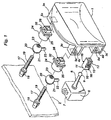
- FIG. 1 is an exploded perspective view of an aimable vehicle headlamp embodying the principles of the present invention;
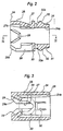
- FIG. 2 is an enlarged axial section through each of two identical socket members used in the aimable headlamp of FIG. 1;
- FIG. 3 is a section taken along the line III-III in FIG. 2;
- FIG. 4 is a view similar to FIG. 2 except that the socket member is shown together with the ball member rotatably received therein and the aiming screw engaged with the ball;
- FIG. 5 is an enlarged vertical section through another socket member in the aimable headlamp of FIG. 1;
- FIG. 6 is a section taken along the line VI-VI in FIG. 5;
- FIG. 7 is an exploded perspective view of another aimable vehicle headlamp embodying the principles of the present invention;
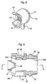
- FIG. 8 is a perspective view of a modified ball member for use in the headlamp of FIGS. 1 or 7;
- FIG. 9 is an axial section through a socket member suitable for use with the ball member of FIG. 8;
- FIG. 10 is a section taken along the line X-X in FIG. 9;
- FIG. 11 is a view similar to FIG. 9 except that the socket member is shown together with the ball member of FIG. 8 rotatably received therein and an aiming screw engaged with the ball member; and
- FIG. 12 is an elevation of another modified ball member for use in the headlamp of FIGS. 1 or 7.
-
- The present invention will now he described in detail as embodied in a vehicle headlamp of the type in which only the reflector, rather than the headlamp unit, is tilted both horizontally and vertically relative to the lamp housing, which is fixed to the vehicle, for aiming the headlamp. With reference to FIG. 1, which illustrates the representative aimable headlamp insofar as is necessary for the full understanding of the invention, a reflector 1, the tiltable member, is shown coupled to a
lamp housing 2, the fixed member, via leveling actuator means including a levelingactuator 6, and two aiming screw means of identical make, each including an aimingscrew 17. Thelamp housing 2 is shown fragmentarily and in phantom outline because of illustrative convenience and of its conventional and well known nature. - The two aiming screw means are shown horizontally spaced from each other, and the leveling actuator means shown spaced downwardly from one of the aiming screw means. However, the aiming screw means just above the leveling actuator means could be replaced by a simple universal connection between the tiltable and fixed members, as in an alternate embodiment of this invention to be disclosed subsequently. The provision of the two aiming screw means, in addition to the leveling actuator means, should not therefore be taken as an essential feature of this invention.
- Molded from an engineering plastic, the reflector 1 has a concave reflective surface which is conventionally rendered reflective to reflect the light from a light source such as a discharge bulb, not shown, forwardly of the vehicle. Three
hollow bosses - The following is a more detailed discussion of the leveling actuator means and the two aiming screw means. How the headlamp is aimed will be explained after the discussion of the noted means.
- With continued reference to FIG. 1 the leveling
actuator 6 has anactuator body 7 which is mounted fast to thelamp housing 2, and a connectingrod 8 projecting forwardly from the actuator body. The connectingrod 8 terminates in aball 9 for pivotal engagement in asocket member 10 which in turn is to be immovably engaged in theboss 3d on the back of the reflector 1. - As illustrated on an enlarged scale in FIGS. 5 and 6, the
socket member 10 is a one-piecenolding of a synthetic resin such as, for example, polyacetal, the molding including asocket portion 11 and a self-locking, snap-onconnector portion 12. For receiving theball 9, thesocket portion 11 defines anelongate socket 13 which may be described as an undereut groove extending along the vertical axis about which is reflector 1 is to be pivoted horizontally by one of the aiming screw means. Cross sectionally shaped and sized to slidably receive theball 9, thesocket 13 has anentrance slot 14 narrower than the ball diameter. The top end of thesocket 13 is closed, and the bottom end thereof left open for admission of theball 9. - The self-locking, snap-on
connector portion 12 of thesocket member 10 is in the shape of a tube of rectangular cross section, sized to fit in thehollow boss 3d on the reflector 1 through anopening 5d in itsrear wall 4d. A pair of opposite side walls of theconnector portion 12 have U-shaped slits formed therein to provide a pair of lockingpawls 15 which grow thicker as they extend toward their free ends directed toward the levelingactuator 6, terminating inledges 15a. A pair offlanges 16 are formed just rearwardly of theledges 15a of the lockingpawls 15. - Such being the construction of the
socket member 10, itsconnector portion 12 may be inserted into thehollow boss 3d on the back of the reflector 1 through theopening 5d in itsrear wall 4d. The pair of lockingpawls 15 will be resiliently deflected toward each other by the pair of opposed edges of thehollow boss wall 4d bounding theopening 5d, as theconnector portion 12 is forced into that opening. Upon full insertion of theconnector portion 12, that is, upon abutment of the pair offlanges 16 against therear wall 4d of theboss 3d, the lockingpawls 15 will spring back, having gone clear of theopening 5d, and positively engage the rear wall of the boss between themselves and theflanges 16. Thesocket member 10 has now been coupled to the reflector 1 against the risk of accidental detachment therefrom. - The
ball 9 of the levelingactuator 6 may then be inserted in thesocket 13 from its bottom end. A slight shifting of theball 9 toward the closed top end of thesocket 13 will suffice to eliminate the likelihood of accidental ball disengagement from the undercut groove. It is thus seen that the levelingactuator 6 is coupled to the reflector 1 in a ball-and-socket fashion. - The two aiming screw means seen in FIG. are alike in construction. Like parts of the two means are therefore identified by like reference characters. Only one such means will be described in detail, it being understood that the same description applies to the other. Broadly, each aiming screw means comprises an aiming
screw 17, aball member 20 having aball 21 with a tappedhole 23 to fit over the aiming screw, and asocket member 24 for rotatably receiving theball 21. - Each aiming
screw 17 is comprised of a head portion rotatably extending through thelamp housing 2 but restrained from axial displacement relative to the same, and a screw-threadedshank 19 projecting forwardly from the lamp housing. Thescrew 17 may be turned in either direction from behind, that is, outside, thelamp housing 2. - Made from
nylon 6 or like plastics, theball member 20 is a one-piece molding of theball 21 and alockpin 22. The tappedhole 23 extends centrally through theball 21 for engagement with the aimingscrew 17. Thelockpin 22 extends radially outwardly of theball 21 and in right angular relationship to the axis of the tappedhole 23. The lockpin 22 functions to prevent the rotation of theball 21 about the axis of the tappedhole 23 relative to thesocket member 24, as will become more understandable from the following detailed description of this socket member. - As illustrated in detail in FIGS. 2-4, the
socket member 24, which may be of polyacetal or like engineering plastic material, integrally comprises asocket portion 25 defining asocket 27 of substantially spherical shape, and a self-locking, snap-onconnector portion 26 for connecting the socket member to thehollow boss socket member 24 as a whole is substantially tubular in shape, with a hollow 24a extending therethrough which is large enough in diameter to receive theshank 19 of the aimingscrew 17 with substantial clearance, as pictured in FIG. 4. - A midportion of the hollow 24a is formed into the
socket 27 for rotatably receiving theball 21 of theball member 20. Theentrance 27a, FIG. 2, of thesocket 27 is formed into a cylinder of the same diameter as the socket for the admission of theball 21 into the socket. Thesocket portion 25 has aslot 28 extending forwardly from the rear end of the socket member and terminating approximately at the boundary betweensocket portion 25 andconnector portion 26. Thelockpin 22 of theball member 20 is to be engaged in thisslot 28 in order to lock theball 21 against rotation about the axis of the tappedhole 23 as the aimingscrew 17 is turned for aiming the lamp. The rear or entrance end portion of theslot 28 is flared, as best seen at 28a in.FIG. 3, for guiding thelockpin 22 into the slot - FIGS. 2 and 3 indicate a pair of
detents 29 formed in diametrically opposite positions on the rear end of thesocket member 24. These detents project into thesocket portion 25 and are angled toward each other as they extend from the rear end of thesocket member 24 toward thesocket 27. Preferably, the opposed faces of thedetents 29 should be concaved. - The
ball 21 is to be forced into thesocket member 24 from its rear end, causing the pair ofdetents 29 to deflect away from each other by virtue of their resiliency. Once theball 21 is seated in thesocket 27, thedetents 29 will spring back into abutment against the ball, thereby firmly retaining the ball in the socket. Thedetents 29 with their concave surfaces will serve the additional purpose of guiding theball 21 into the socket. As theball 21 is so guided into the socket, thelockpin 22 on the ball will also be positively guided into theslot 28 by itsflaring end 28a. - It is understood that the aiming
screw 17 is engaged with theball 21 before this ball is pushed into thesocket member 24. Thus, when theball 21 is seated in thesocket 27 as depicted in FIG. 4, theshank 19 of the aimingscrew 17 will be received with considerable clearance in the hollow 24a in thesocket member 24, permitting relative angular displacement betweenball member 20 andsocket member 24. - The self-locking, snap-on
connector portion 26 of thesocket member 24 includes atube 31 of rectangular cross section, sized to fit in thehollow boss opening 5c or 5s in itsrear wall tube 31 have U-shaped slits cut therein to provide a pair of lockingpawls 32 which grow thicker as they extend toward their free rear ends from their fixed front ends, terminating inledges 32a. Aflange 30 is formed around thesocket member 24, in a position just rearwardly of theledges 32a of the lockingpawls 32. - How the
connector portion 26 of thesocket member 24 is coupled to thehollow boss connector portion 12 of thesocket member 10 is coupled to thehollow boss 3d. Upon full insertion of theconnector portion 26, the pair of lockingpawls 32 will positively engage therear wall boss flange 30 on thesocket member 24. - In the practice of this invention the opening 5s in the
right hand boss 3s, as seen in FIG. 1, on the reflector 1 should preferably be made greater in horizontal dimension than theconnector portion 26 of thesocket member 24, permitting some lateral displacement of the socket member relative to the reflector 1. Such lateral displacement will be effective to take up the misalignment that may arise betweenreflector boss 3s and the associated aimingscrew 17 in horizontally aiming the lamp. - The aiming
screw 17 seen to the right in FIG. 1 is turned in either direction, theball 21 will relatively travel forwardly or rearwardly of the screw together with thesocket member 24, the rotation of the ball with the aiming screw being prevented by thelockpin 22 engaged in theslot 28 in the socket member. Thus the reflector 1 will tilt about an axis passing through the geometric center of theball 9 of the levelingactuator 6 and that of theball 21 of the left hand aiming screw means. - The leveling
actuator 6 is to be energized, either automatically or by remote control, for tilting the reflector 1 about another axis, at right angles with the first described axis, passing through the geometric centers of theballs 21 of both aiming screw means. It is also possible in this particular embodiment to turn the two aimingscrews 17 in the same direction and at the same time. The reflector 1 will then tilt about an axis passing through the center of the levelingactuator ball 9. - The reflector 1 will move very smoothly when tilted in either direction as above, thanks to the provision of the ball-and-socket joints in all of the three connections between the fixed and the tiltable members. It should also be appreciated that the
ball 9 of the levelingactuator 6 is slidably received in the vertically elongated undercutgroove 13 in thesocket member 10. This modified ball-and-socket joint is preferred because it allows relative vertical displacement of theball 9 and thesocket member 10 when the lamp is being aimed vertically, assuring even smoother tilting of the reflector 1 in that direction. - The aimable vehicle headlamp shown in FIG. 7 differs from the FIG. I device only the pivotal connection employed at the upper, left hand corner of the reflector 1 in place of the aiming screw of the preceding embodiment. The pivotal connection is a ball-and-socket joint comprises a
ball member 33 coupled to thelamp housing 2, and thesocket member 24 coupled to the reflector 1. Theball member 33 has aball 36 formed on one end of a connectingrod 35 which has aknurled part 34 embedded in thelamp housing 2. Theball 36 is rotatably received in thesocket portion 25 of thesocket member 24, which also has the self-locking, snap-onconnector portion 26 received and locked in thehollow boss 3c on the back of the reflector 1. Thesocket member 24 used in this alternate embodiment can be of the same construction as that shown in FIGS. 2-4, except perhaps for the absence of theslot 28 for receiving thelockpin 22 of theball member 20. - The reflector 1 is tiltable in two orthogonal directions by the leveling
actuator 7 and by the aimingscrew 17. The aiming screw means were used in the FIG. 1 embodiment instead of the pivotal connection of this alternate embodiment because the aiming screw means, including the ball-and-socket joint according to the invention, additionally serve as universal joint between the fixed and the tiltable members. - FIG. 8 shows a modified
ball member 37, and FIGS. 9 and 10 a correspondingly modifiedsocket member 42. FIG. 11 shows theball member 37 rotatably received in thesocket member 42, with the aimingscrew 17 extending through the tapped hole in the ball member. The modifiedball member 37 andsocket member 42 are both intended for use as parts of the aiming screw means in the aimable headlamps of both FIGS. 1 and 7. - The modified
ball member 37 features a pair of opposed, flaringguide wings 40 formed on theball 21 in one piece therewith for guiding the aimingscrew 17 into the tappedhole 23. The opposed faces of theguide wings 40 are concaved for more infallibly guiding the aiming screw into thehole 23. - A comparison of FIGS. 9 and 10 with FIGS. 2 and 3 will reveal that the modified
socket member 42 is identical with the first disclosedsocket member 24 except that the pair ofdetents 29 are formed not directly on the rear end of thesocket portion 25, as in thesocket member 24, but on the rear ends of a pair oftongues 47. These tongues project rcarwardly from diametrically opposite positions on the rear end of thesocket portion 25. - When the
ball member 37 is engaged in thesocket member 42 as pictured in FIG. 11, thetongues 47 provide spaces therebetween for receiving the pair of flaring guides 40 of the ball member in an interdigitating manner. It is understood that the spaces are large enough to accommodate theguides 40 with sufficient clearances to permit required degrees of angular displacement of theball 21 relative to thesocket member 42. - FIG. 12 shows another modified
ball member 55 having ahole 53 which is not tapped as in the foregoing embodiments but which has, instead, a plurality ofridges 52 running lengthwise on the surface bounding thehole 53. As the aiming screw is driven into thehole 53, threads will be cut in theridges 52. - Not withstanding the foregoing detailed disclosure, it is not desired that the present invention be limited by the exact details of the illustrated embodiments. For example, the invention is applicable not only to vehicle lamps having a tiltable reflector but also to those in which a lamp unit is tilted relative to the vehicle.
Claims (9)
- An aiming mechanism for a vehicle lamp wherein the aiming mechanism is able to tilt a tiltable member (1) of the vehicle lamp relative to a fixed member (2) of the vehicle lamp in either of two orthogonal tilting directions, the aiming mechanism comprising:whereby rotation of the aiming screw (17) causes the tiltable member (1) to tilt relative to the fixed member (2) about the pivotal connection (9) while the socket member (24) on the tiltable member rotates around the ball (21) to afford smooth tilting motion of the tiltable member (1).a) an aiming screw (17) rotatably supported by the fixed member (2);b) a socket member (24) affixed to the tiltable member (1), the socket member having an opening extending therethrough for receiving the aiming screw (17) with clearance, part of the opening being formed into a socket (27); andc) a pivotal connection (9) between the fixed member (2) and the tiltable member (1), characterised byd) a ball (21) having a hole (23) extending therethrough for receiving and screw-threadedly engaging the aiming screw (17), the ball (21) being received in the socket (27) in the socket member (24) and thereby constraining the ball (21) to linear motion along the aiming screw (17) while allowing relative rotation of the socket member (24) about the ball; ande) means (22) on the ball (21) for locking it against rotation relative to the socket member (24) about an axis of the hole (23) therein;
- An aiming mechanism for a vehicle lamp as claimed in claim 1, wherein the locking means (22) comprise a lockpin formed on the ball (21) and received in a slot (28) in the socket member (24).
- An aiming mechanism for a vehicle lamp as claimed in claim 1 or claim 2, wherein the socket member (24) has a pair of opposite ends between which the opening extends, and wherein the socket member is formed to include at least a pair of detents (29) in diametrically opposite positions on one end thereof, the detents projecting into the opening in the socket member (24) for rotatably retaining the ball (21) therein.
- An aiming mechanism for a vehicle lamp as claimed in claim 3, wherein the detents (29) on the socket member (24) are angled toward each other as they extend from one end toward the other end of the socket member in order to facilitate the admission of the aiming screw (17), together with the ball (21) thereon, into the opening in the socket member.
- An aiming mechanism for a vehicle lamp as claimed in any one of the preceding claims, wherein the ball (21) is formed to include guide means (40) for guiding the aiming screw (17) into threaded engagement in the hole (23) in the ball.
- An aiming mechanism for a vehicle lamp as claimed in claim 5, wherein the guide means comprises a pair of opposed, flaring guide wings (40) formed on the ball (21).
- An aiming mechanism for a vehicle lamp as claimed in claim 6, wherein the detents are interdigitated with the guide wings (40) on the ball (21).
- An aiming mechanism for a vehicle lamp as claimed in any one of the preceding claims, wherein first and second aiming screws (17) are rotatably supported by the fixed member (2) for tilting the tiltable member (1) relative to the fixed member about first and second axes respectively, the first axes perpendicular to the second axes.
- An aiming mechanism for a vehicle lamp as claimed in any one of the preceding claims, wherein the pivotal connection (9) between the fixed member (2) and the tiltable member (1) includes a connecting rod (8) which is adjustable in length.
Applications Claiming Priority (3)
| Application Number | Priority Date | Filing Date | Title |
|---|---|---|---|
| JP189929/96 | 1996-07-02 | ||
| JP18992996 | 1996-07-02 | ||
| JP08189929A JP3128616B2 (en) | 1996-07-02 | 1996-07-02 | Optical axis adjustment device for vehicle lighting |
Publications (3)
| Publication Number | Publication Date |
|---|---|
| EP0816167A2 EP0816167A2 (en) | 1998-01-07 |
| EP0816167A3 EP0816167A3 (en) | 1998-10-07 |
| EP0816167B1 true EP0816167B1 (en) | 2002-01-02 |
Family
ID=16249579
Family Applications (1)
| Application Number | Title | Priority Date | Filing Date |
|---|---|---|---|
| EP97304679A Expired - Lifetime EP0816167B1 (en) | 1996-07-02 | 1997-06-27 | Aiming mechanism for vehicle lamps |
Country Status (4)
| Country | Link |
|---|---|
| US (1) | US5908239A (en) |
| EP (1) | EP0816167B1 (en) |
| JP (1) | JP3128616B2 (en) |
| DE (1) | DE69709446T2 (en) |
Families Citing this family (38)
| Publication number | Priority date | Publication date | Assignee | Title |
|---|---|---|---|---|
| JP2000057824A (en) * | 1998-08-04 | 2000-02-25 | Koito Mfg Co Ltd | Vehicle headlights |
| JP3888655B2 (en) * | 1998-11-11 | 2007-03-07 | 株式会社小糸製作所 | Automotive headlamps |
| JP2000251510A (en) * | 1999-02-25 | 2000-09-14 | Koito Mfg Co Ltd | Vehicle lighting |
| JP3913416B2 (en) * | 1999-09-13 | 2007-05-09 | 株式会社小糸製作所 | Vehicle lighting |
| JP3887526B2 (en) * | 1999-09-30 | 2007-02-28 | 株式会社小糸製作所 | Leveling device for vehicle headlamps |
| JP3718124B2 (en) * | 2000-12-28 | 2005-11-16 | 株式会社小糸製作所 | Reflector movable automotive headlamp |
| JP3888672B2 (en) * | 2001-12-25 | 2007-03-07 | 株式会社小糸製作所 | Reflector movable automotive headlamp |
| US6692176B1 (en) | 2002-04-02 | 2004-02-17 | Asyst Technologies Llc | Ball socket with locking feature |
| US6824300B2 (en) * | 2002-06-19 | 2004-11-30 | Guide Corporation | Headlamp mounting plug |
| JP2004196211A (en) * | 2002-12-20 | 2004-07-15 | Koito Mfg Co Ltd | Vehicle headlights |
| DE10322265A1 (en) * | 2003-05-16 | 2004-12-09 | Stabilus Gmbh | Ball joint |
| JP2005014821A (en) * | 2003-06-27 | 2005-01-20 | Koito Mfg Co Ltd | Head lamp for automobile |
| US7252419B1 (en) * | 2003-12-09 | 2007-08-07 | Honda Motor Co., Ltd. | Motorcycle headlight assembly |
| JP4599085B2 (en) * | 2004-04-16 | 2010-12-15 | スタンレー電気株式会社 | Position adjustment member and optical axis adjustment device for vehicle lamp using the position adjustment member |
| US7073930B2 (en) * | 2004-09-01 | 2006-07-11 | Lear Corporation | Aimable vehicle lamp assembly |
| US7249873B2 (en) * | 2004-09-07 | 2007-07-31 | Lear Corporation | Adjustable light beam device for aimable vehicle lamp assembly and method |
| US7500768B2 (en) * | 2005-12-07 | 2009-03-10 | Jack Chen | Motorized controls for a headlight of a vehicle |
| DE102007023478A1 (en) * | 2007-01-12 | 2008-07-17 | Stabilus Gmbh | Connection element for connecting components |
| JP2008243604A (en) * | 2007-03-27 | 2008-10-09 | Koito Mfg Co Ltd | Vehicle lamp |
| JP5287324B2 (en) * | 2009-02-13 | 2013-09-11 | 市光工業株式会社 | Vehicle lighting |
| DE102009002101A1 (en) * | 2009-04-01 | 2010-10-14 | Robert Bosch Gmbh | Method and device for illuminating road side areas |
| EP2327584B1 (en) * | 2009-11-25 | 2015-07-08 | Hella KGaA Hueck & Co. | Adjustment system for at least one light module of a lighting device of a vehicle and lighting device for a vehicle |
| CN101709854B (en) * | 2009-12-11 | 2011-07-13 | 奇瑞汽车股份有限公司 | Installation and positioning structure of automobile lamp |
| DE102010025778B4 (en) * | 2010-07-01 | 2012-11-08 | Gm Global Technology Operations, Llc | Device for connecting two components |
| JP5706702B2 (en) * | 2011-02-03 | 2015-04-22 | 株式会社小糸製作所 | Vehicle headlamp |
| JP5706701B2 (en) * | 2011-02-03 | 2015-04-22 | 株式会社小糸製作所 | Vehicle headlamp |
| JP6062178B2 (en) * | 2012-08-01 | 2017-01-18 | 株式会社小糸製作所 | Nut member |
| JP6097548B2 (en) * | 2012-12-17 | 2017-03-15 | 株式会社小糸製作所 | Vehicle lighting |
| US20160017913A1 (en) * | 2014-07-16 | 2016-01-21 | Spyraflo, Inc. | Selectively orientable static bearing assembly |
| CN104266147A (en) * | 2014-09-28 | 2015-01-07 | 江苏申通汽车零部件有限公司 | Reflector adjusting mechanism for automobile lamp |
| KR102317238B1 (en) * | 2014-11-11 | 2021-10-26 | 현대모비스 주식회사 | Lamp apparatus of an automobile |
| FR3056487B1 (en) | 2016-09-26 | 2018-11-02 | Valeo Vision | LIGHTING AND / OR SIGNALING DEVICE FOR MOTOR VEHICLE AND ASSEMBLY COMPRISING MULTIPLE DEVICES |
| US10457198B2 (en) * | 2017-03-27 | 2019-10-29 | Whelen Engineering Company, Inc. | Accessory mounting system |
| US10204807B2 (en) * | 2017-04-25 | 2019-02-12 | Taiwan Semiconductor Manufacturing Co., Ltd. | Apparatus and method for processing wafer |
| CN207067635U (en) * | 2017-07-05 | 2018-03-02 | 深圳市光峰光电技术有限公司 | Optics module |
| CN108469167B (en) * | 2018-02-01 | 2020-05-15 | 诸暨市宏益机械厂 | A drying-machine for battery manufacturing |
| CN109237353A (en) * | 2018-09-13 | 2019-01-18 | 湖南华特光电科技有限公司 | A kind of wall lamp |
| EP4201743B1 (en) * | 2021-12-22 | 2024-07-10 | ZKW Group GmbH | Floor lighting module for a motor vehicle for generating floor lighting distribution |
Citations (1)
| Publication number | Priority date | Publication date | Assignee | Title |
|---|---|---|---|---|
| DE4445768A1 (en) * | 1993-12-21 | 1995-07-20 | Koito Mfg Co Ltd | Vehicle headlights |
Family Cites Families (10)
| Publication number | Priority date | Publication date | Assignee | Title |
|---|---|---|---|---|
| JPS5936503U (en) * | 1982-08-31 | 1984-03-07 | 株式会社小糸製作所 | Light equipment |
| US4845598A (en) * | 1987-09-22 | 1989-07-04 | Koito Seisakusho Co., Ltd. | Headlight for automobile |
| US4881152A (en) * | 1987-09-22 | 1989-11-14 | Koito Seisakusho Co., Ltd. | Headlight for automobile |
| JPH0788151B2 (en) * | 1988-05-06 | 1995-09-27 | 株式会社小糸製作所 | Vehicle headlamp tilting device |
| JPH0787041B2 (en) * | 1988-11-24 | 1995-09-20 | 株式会社小糸製作所 | Headlight assembly method |
| JP2663310B2 (en) * | 1991-04-05 | 1997-10-15 | 株式会社小糸製作所 | Automotive headlights |
| FR2689611B1 (en) * | 1992-04-06 | 1994-07-08 | Valeo Vision | DEVICE FOR MOUNTING A PORTION OF A MOTOR VEHICLE PROJECTOR. |
| US5360282A (en) * | 1993-11-01 | 1994-11-01 | General Motors Corporation | Vehicle headlamp adjuster ball and socket assembly |
| JPH07320505A (en) * | 1994-05-19 | 1995-12-08 | Koito Mfg Co Ltd | Aiming mechanism for automotive lighting |
| JP3074557B2 (en) * | 1994-11-24 | 2000-08-07 | 株式会社小糸製作所 | Vehicle headlamp |
-
1996
- 1996-07-02 JP JP08189929A patent/JP3128616B2/en not_active Expired - Fee Related
-
1997
- 1997-06-27 EP EP97304679A patent/EP0816167B1/en not_active Expired - Lifetime
- 1997-06-27 DE DE69709446T patent/DE69709446T2/en not_active Expired - Fee Related
- 1997-07-01 US US08/886,175 patent/US5908239A/en not_active Expired - Lifetime
Patent Citations (1)
| Publication number | Priority date | Publication date | Assignee | Title |
|---|---|---|---|---|
| DE4445768A1 (en) * | 1993-12-21 | 1995-07-20 | Koito Mfg Co Ltd | Vehicle headlights |
Also Published As
| Publication number | Publication date |
|---|---|
| JP3128616B2 (en) | 2001-01-29 |
| US5908239A (en) | 1999-06-01 |
| EP0816167A2 (en) | 1998-01-07 |
| DE69709446T2 (en) | 2002-08-01 |
| DE69709446D1 (en) | 2002-02-07 |
| EP0816167A3 (en) | 1998-10-07 |
| JPH1021705A (en) | 1998-01-23 |
Similar Documents
| Publication | Publication Date | Title |
|---|---|---|
| US5908239A (en) | Aiming mechanism for vehicle lamps | |
| US6550947B1 (en) | Vehicle lamp | |
| US5546283A (en) | Vehicular headlamp having improved assembly efficiency | |
| US4333131A (en) | Headlight mounting and adjustment mechanism | |
| US5678915A (en) | Easy-to-assemble aiming mechanism for vehicle lamps | |
| JP3128617B2 (en) | Leveling adjustment device for vehicle lighting | |
| US4707771A (en) | Support shoe for a vehicle headlamp assembly | |
| US6231220B1 (en) | Vehicle lamp | |
| US5577836A (en) | Headlamp for vehicles | |
| JP2832748B2 (en) | Headlight position adjustment device for automobile | |
| US11719381B2 (en) | Adjustable linkage arm | |
| US20210140602A1 (en) | Lamp for vehicle | |
| US4870544A (en) | Optical-axis adjusting apparatus for automotive lights | |
| US5707134A (en) | Vehicular lamp | |
| US6338567B1 (en) | Gearless headlamp adjustor | |
| US5530629A (en) | Optical axis adjusting device for automotive headlights | |
| US4707768A (en) | Retainer assembly | |
| US5161876A (en) | Lamp assembly | |
| JP3193638B2 (en) | Vehicle lighting | |
| EP0431803A2 (en) | Lamp assembly | |
| US20230249607A1 (en) | Adjustment device for a vehicle light emitting module | |
| US6923562B2 (en) | Headlight assembly having vertical headlamp adjuster | |
| GB2233754A (en) | Adjustable vehicle head light assembly | |
| JP3094208B2 (en) | Aiming mechanism in vehicle lighting | |
| US6443607B1 (en) | Headlamp adjusting attachment nut |
Legal Events
| Date | Code | Title | Description |
|---|---|---|---|
| PUAI | Public reference made under article 153(3) epc to a published international application that has entered the european phase |
Free format text: ORIGINAL CODE: 0009012 |
|
| AK | Designated contracting states |
Kind code of ref document: A2 Designated state(s): DE GB |
|
| PUAL | Search report despatched |
Free format text: ORIGINAL CODE: 0009013 |
|
| AK | Designated contracting states |
Kind code of ref document: A3 Designated state(s): AT BE CH DE DK ES FI FR GB GR IE IT LI LU MC NL PT SE |
|
| 17P | Request for examination filed |
Effective date: 19981201 |
|
| AKX | Designation fees paid |
Free format text: DE GB |
|
| 17Q | First examination report despatched |
Effective date: 20000524 |
|
| GRAG | Despatch of communication of intention to grant |
Free format text: ORIGINAL CODE: EPIDOS AGRA |
|
| GRAG | Despatch of communication of intention to grant |
Free format text: ORIGINAL CODE: EPIDOS AGRA |
|
| GRAH | Despatch of communication of intention to grant a patent |
Free format text: ORIGINAL CODE: EPIDOS IGRA |
|
| GRAH | Despatch of communication of intention to grant a patent |
Free format text: ORIGINAL CODE: EPIDOS IGRA |
|
| GRAA | (expected) grant |
Free format text: ORIGINAL CODE: 0009210 |
|
| REG | Reference to a national code |
Ref country code: GB Ref legal event code: IF02 |
|
| AK | Designated contracting states |
Kind code of ref document: B1 Designated state(s): DE GB |
|
| REF | Corresponds to: |
Ref document number: 69709446 Country of ref document: DE Date of ref document: 20020207 |
|
| PLBE | No opposition filed within time limit |
Free format text: ORIGINAL CODE: 0009261 |
|
| STAA | Information on the status of an ep patent application or granted ep patent |
Free format text: STATUS: NO OPPOSITION FILED WITHIN TIME LIMIT |
|
| 26N | No opposition filed | ||
| PGFP | Annual fee paid to national office [announced via postgrant information from national office to epo] |
Ref country code: GB Payment date: 20060621 Year of fee payment: 10 |
|
| GBPC | Gb: european patent ceased through non-payment of renewal fee |
Effective date: 20070627 |
|
| PG25 | Lapsed in a contracting state [announced via postgrant information from national office to epo] |
Ref country code: GB Free format text: LAPSE BECAUSE OF NON-PAYMENT OF DUE FEES Effective date: 20070627 |
|
| PGFP | Annual fee paid to national office [announced via postgrant information from national office to epo] |
Ref country code: DE Payment date: 20090626 Year of fee payment: 13 |
|
| PG25 | Lapsed in a contracting state [announced via postgrant information from national office to epo] |
Ref country code: DE Free format text: LAPSE BECAUSE OF NON-PAYMENT OF DUE FEES Effective date: 20110101 |