This application claims the filing date of
Provisional Application Serial No. 60/021,193 filed on
July 3, 1996 by inventor Douglas Pherigo and entitled
Combined Right-Hand/Left-Hand Horizontal Headlamp
Indicator Device
".
This invention is generally directed to a non-handed
indicator device for indicating the horizontal and
vertical zero positions of a vehicle headlamp in a
vehicle, such as a truck or an automobile. More
particularly, the invention contemplates a single left-hand/right-hand
indicator device for indicating the
horizontal zero position of a headlamp in a vehicle, and
usable with either headlamp.
Headlamp indicator devices need to be left-hand or
right-hand oriented in some instances resulting in a need
for additional mounting components and leading to
confusion on the assembly line. Prior art indicator
devices use a left-hand horizontal scale and a right-hand
horizontal scale on each indicator device thereby
requiring separate indicators for left-hand or right-hand
applications, see United States Patent No. 5,317,486.
This presents some problems in the overall assembly
operation as the operator must be sure he or she has the
correct components for the right-hand and left-hand sides
as they are not interchangeable.
The present invention presents a novel horizontal
headlamp non-handed indicator device which provides for
right-hand and left-hand applications and which can also
indicate proper vertical positioning. Other features and
advantages will become apparent upon a reading of the
attached specification in conjunction with an examination
of the attached drawings.
OBJECTS AND SUMMARY OF THE INVENTION
A general object of the present invention is to
provide a novel non-handed indicator device for denoting
the proper aiming position of a headlamp in a vehicle,
such as a truck, automobile or the like.
An object of the present invention is to provide a
novel non-handed indicator device that is a single
component that is useable in both right-hand and left-hand
applications for denoting the horizontal zero
position of a headlamp in a vehicle, and usable with
either headlamp on the vehicle.
Another object of the present invention is to
provide a novel non-handed indicator device that denotes
proper aiming of both horizontal and vertical positioning
of the headlamp.
Briefly, and in accordance with the foregoing, the
present invention discloses a non-handed headlamp
position indicator device for denoting the proper aiming
or "zero position" of a movable reflector component
mounted in a stationary component of a headlamp
arrangement on a vehicle, such as a truck, automobile or
the like, so that a vehicle mechanic can easily return
the headlamp mounted in the moveable reflector component
to the zero position. The non-handed indicator device of
the present invention utilizes one component that can be
used for right-hand and left-hand applications.
The non-handed indicator device includes a bracket
mounted on the reflector beneath an opening in the
stationary housing. The bracket has a U-shaped track
portion connected thereto and a projection which extends
outwardly from the bracket and engages in a pocket formed
in the reflector component. An arrow member is mounted
on the U-shaped track portion and is slidable relative
thereto. The track portion includes a curved section and
a pair of relatively linear sections at both ends of the
curved section. The curved section has a width which is
less than the width of the relatively linear sections so
that the arrow member can be easily slid around the
length of the U-shaped track portion. For each headlamp,
a scale, which includes a zero indicia, is mounted on the
stationary housing proximate to the opening towards the
pivot point.
After the reflector component is moved to its
desired zero position, the arrow member is slid along the
track portion until it aligns with the zero indicia on
the scale for providing an indication of the horizontal
zero position of the reflector. The arrow member is not
thereafter moved. If the reflector becomes misaligned
for any reason, the reflector can easily be returned to
the zero position by moving the reflector until the arrow
member once again aligns with the zero indicia on the
scale.
If desired, the non-handed indicator device of the
present invention can also include a bubble level
assembly mounted on the bracket for providing an
indication of when the reflector is vertically zeroed.
Such bubble level assemblies are well-known in the art
for providing an indication of the vertical zero position
of the reflector, see United States Patent No. 5,317,486.
BRIEF DESCRIPTION OF THE DRAWINGS
The organization and manner of the structure and
operation of the invention, together with further objects
and advantages thereof, may best be understood by
reference to the following description, taken in
connection with the accompanying drawings, wherein like
reference numerals identify like elements in which:
DETAILED DESCRIPTION OF THE ILLUSTRATED EMBODIMENT
While the invention may be susceptible to embodiment
in different forms, there is shown in the drawings, and
herein will be described in detail, a specific embodiment
with the understanding that the present disclosure is to
be considered an exemplification of the principles of the
invention, and is not intended to limit the invention to
that as illustrated and described herein.
The present invention discloses a non-handed
headlamp position indicator device 20 for denoting the
proper aiming or "zero position" of a movable reflector
component 22 mounted in a stationary housing 24 of a
headlamp arrangement 26 of a vehicle 28, such as a truck,
automobile or the like, so that a vehicle mechanic can
easily return the headlamp mounted in the moveable
reflector component 22 to the zero position. Prior to
the present invention, headlamp position indicators
needed to be left-hand or right-hand oriented in some
instances resulting in a need for additional mounting
components and leading to confusion on the assembly line.
The non-handed indicator device 20 of the present
invention eliminates the need for additional mounting
components because of right-hand or left-hand
applications and instead, utilizes one component that can
be used for right-hand and left-hand applications.
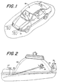
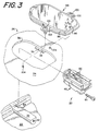
A vehicle 28, such as a truck or automobile, has
headlamp 30 on the front on either side thereof. The
headlamp 30 can be adjusted vertically as well as
horizontally. Horizontal zeroing will take place vis-a-vis
the novel track portion of the non-handed indicator
device 20 as described herein. Vertical zeroing will
take place vis-a-vis the non-handed indicator device 20
of the present invention as described herein, utilizing a
bubble level as is well known in the art, see United
States Patent No. 5,317,486.
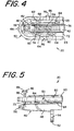
The movable reflector component 22, to which the
non-handed indicator device 20 is mounted, can pivot or
be adjusted in the horizontal plane relative to the
stationary housing 24 by means of a headlamp adjustor
mechanism 25 which pivots the reflector component 22
around a fixed pivot 23 on the stationary housing 24. A
like adjustor mechanism 27 is employed to move or pivot
the reflector component 22 in the vertical plane.
Headlamp adjustor mechanisms are well-known in the art
and a variety of mechanisms can be used with the present
invention.
The headlamp position indicator device 20 of the
present invention is affixed to a projection 32 which is
formed on the reflector component 22 and within a pocket
34 formed on the movable reflector component 22 proximate
to and spaced above the projection 32. The projection 32
and the pocket 34 may be integrally formed on the
reflector component 22 or may be provided as separate
components which are secured to the reflector component
22 by suitable means. The reflector component 22,
projection 32 and the pocket 34 are fabricated from a
thermal setting material which has a hardness that is
close to ceramic materials.
The indicator device 20 of the present invention is
mounted to the projection 32 immediately below an opening
36 in the stationary housing 24 so that the indicator
device 20 can be viewed from the exterior of the headlamp
arrangement 26. A horizontal scale 38 is fixed on the
stationary housing 24 proximate to the opening 36 and
does not move relative to the reflector component 22. On
each headlamp arrangement 26, the horizontal scale 38 is
mounted on the stationary housing 24 between the
indicator device 20 and the fixed pivot 23 on each
headlamp. The scale 38 in the illustrated embodiment is
provided on a member which extends outwardly from the
edge of the opening 36. The scale 38 could be provided
on a decal affixed to the outer surface of the housing 24
proximate to the opening 36. The scale 38 has a
plurality of graduations 39, which are made from black
two part epoxy ink or ceramic, formed thereon. The
projection 32 and opening 36 are provided at a
predetermined distance from the moveable reflector
component pivot 23 location.
The indicator device 20 of the present invention
includes a molded plastic mounting bracket 40, a bubble
level assembly 42, a vial clip or stamping 44 and an
adjusting screw 46.
The mounting bracket 40 includes a base portion 48
and a track portion 50. The base portion 48 and the
track portion 50 may be integrally formed as one-piece or
as separate components, as illustrated. Each of the base
portion 48 and the track portion 50 is formed from a
suitable material, such as nylon.
The base portion 48 is elongate and is generally a
rectangularly-shaped frame 49 with a cutout in the middle
of the frame 49. A boss 52 extends downwardly from the
frame 49, perpendicular thereto, and has an aperture 54
formed therethrough. A forward extending projection 56
is provided on the front of the frame 49. The forward
extending projection 56 is a locating and front lock down
feature which mates with the pocket 34 formed on the
moveable reflector component 22.
The track portion 50 of the mounting bracket 40 is
U-shaped having a curved section 58 and two relatively
linear sections 60, 62 which extend from the ends of the
curved section 58 and are parallel to each other. Each
of the relatively linear sections 60, 62 has a
predetermined height and thickness. The curved section
58 of the U-shaped track portion 50 has a predetermined
height, and a predetermined thickness which is less than
the predetermined thickness of the relatively linear
sections 60, 62. This reduced thickness of the curved
section 58 allows the indicator member 66 to move along
this curved section. A protrusion 63 extends upwardly
from the end of each of the relatively linear sections
60, 62. The track portion 50 has four mounting legs 64
for connecting the track portion 50 to the base portion
48 as described herein. Other than the four mounting
legs 64, the track portion 50 is spaced apart from the
base portion 48 a predetermined distance.
An indicator arrow member 66 is releasibly and
slidably engaged with the track portion 50. The
indicator arrow member 66 is formed from a clip 68 and
includes a pointer 70 and is stamped or formed from a
suitable material, such as metal. The clip 68 is
removably attached to and generally encircles the track
portion 50, such that a bifurcated tang portion 69 of the
clip 68 is engaged within the spacing between the track
portion 50 and the base portion 48 of the mounting
bracket 40. The clip 68 is slidable relative to the
track portion 50. The pointer 70 points outwardly from
the U-shaped track portion 50 for reasons described
herein. The U-shaped design of the track portion 50 is
utilized so that the indicator arrow member 66 can be
positioned at any location along the relatively linear
sections 60, 62 or curved section 58 of the track portion
50, thereby effectively eliminating the left-hand/right-hand
problem as described herein. As shown in FIGURE 4,
the indicator arrow member 66 is shown in solid lines on
the upper side along the relatively linear section 62 of
the device 20 and in phantom lines on the curved section
58 and on the lower side along the relatively linear
section 62 of the device 20. The positions shown in
phantom lines are examples of alternate positions to
which the indicator arrow member 66 can be moved. The
protrusions 63 prevent the indicator arrow member 66 from
being slid off of the end of the relatively linear
sections 60, 62 of the track portion 50.
The stamping 44 is provided for mounting the bubble
level assembly 42 on the mounting bracket 40. The
stamping 44 is formed from a suitable material, such as
stainless steel, and includes an outer rectangularly-shaped
frame portion 72 with a tongue portion 74 that
extends into the middle of the frame portion 72. The
tongue portion 74 and the frame portion 72 are spaced
apart from each other and the tongue portion 74 is
flexible relative to the frame portion 72. The frame
portion 72 is mounted on the base portion 48 of the
mounting bracket 40 by suitable means, such as adhesive.
A forward extending tang 73 is provided along the front
of the frame portion 72 at the center of the front
thereof and sits against the base portion 48.
The stamping 44 is snap-fit or otherwise suitably
secured to the upper surface of the base portion 48 and
sits within a groove 75 formed in the upper surface of
the base portion 48 to hold the periphery of the stamping
44 in place. The mounting legs 64 of the track portion
50 are preferably secured on the upper surface of the
stamping 44 by suitable means, such as adhesive, unless
the track portion 50 and base portion 48 are integrally
formed together. The mounting legs 64 are positioned
between the relatively linear sections 60, 62 of the U-shaped
track portion 50 and the stamping 44. Each
mounting leg 64 does not extend across the entire width
of the respective relatively linear sections 60, 62 such
that each mounting leg 64 is spaced a predetermined
distance from the outermost surface of the relatively
linear sections 60, 62 of the track portion 50.
The bubble level assembly 42 includes a vial 76
which holds a liquid which has an air bubble 78 formed
therein. The vial 76 is preferably formed from Pyrex or
borosilicate. Pyrex is preferred because it can
withstand heat more readily than other transparent
materials. The liquid housed in the vial 76 is
preferably mineral spirit and a green fluorescent may be
added to the liquid. The vial 76 has a plurality of
graduations 80 made from black two part epoxy ink or
ceramic.
The vial 76 has a boss 82 integrally formed
therewith and which extends outwardly therefrom. The
boss 82 is of a predetermined height and has an elongated
threaded bore 83 formed therethrough, through which the
adjusting screw member 46 is engaged. The vial 76 is
mounted on the tongue portion 74 of the stamping 44 by
suitable means, such as adhesive or by providing tabs on
the bottom the vial 76 and heat staking the tabs through
apertures 85 provided in the tongue portion 74 of the
stamping 44. The boss 82 bridges the gap between the
tongue portion 74 and the frame portion 72 of the
stamping 44 such that the boss 82 overlaps the frame
portion 72 and the forwardly extending tang 73 of the
stamping 44. The threaded bore 83 through the boss 82
aligns with the forwardly extending tang 73 of the
stamping 44.
The adjusting screw member 46 is disposed inwardly
or forward of the vial 76 and is engaged with the
threaded bore 83 through the boss 82 such that the bottom
end of the adjusting screw member 46 engages against the
tang 73. The adjusting screw member 46 has a threaded
shank portion 86 which extends from a head 88. The head
88 has a TORX® drive system provided thereon for rotating
the adjusting screw member 46, but may be provided with
other hex drive systems.
To mount the indicator device 20 on the projection
32 formed on the reflector component 22, the projection
56 is seated in the pocket 34 formed on the reflector
component 22. This eliminates a screw as well as
preventing the forward edge of the bubble vial 76 from
being forced up. When the projection 56 is fully seated
within the pocket 34, the base portion 48 sits on top of
the projection 32 and the boss 52 abuts against the end
of the projection 32. A screw 90 is provided and is
passed through the aperture 54 in the boss 52 and is
inserted into a threaded bore 92 in the end of the
projection 32. The screw 90 has a threaded shank portion
which extends from a head. The head has a TORX® drive
system provided thereon for rotating the screw 90, but
may be provided with other hex drive systems. The screw
90 is tightened to secure the rear end of the indicator
device 20 to the projection 32. When mounted, the
indicator device 20 is seated below the opening 36 and
proximate to the horizontal scale 38.
Thereafter, a view window 94 is mounted on the
stationary housing 24 and over the opening 36 to prevent
the entrance of foreign materials into the stationary
housing 24. The distance from the view window 94 to the
indicator device 20 will vary with the design of the
headlamp arrangement 26. The view window 94 includes an
outer portion 96 and a middle portion 98, each made from
a transparent material 98, preferably clear, hard
plastic. Means for mounting the view window 94 to the
stationary housing 24 is provided and may comprise a pair
of screws 100 which mount through bosses 102 extending
outwardly from the outer portion 96 and seat within
corresponding threaded apertures 104 provided in the
stationary housing 24 proximate to the opening 36. Each
screw 100 has a threaded shank portion which extends from
a head. The head has a TORX® drive system provided
thereon for rotating the screw, but may be provided with
other hex drive systems. Thus, when mounted, the
indicator device 20 is positioned immediately below the
opening 36 in the stationary housing 24 so that the U-shaped
track portion 50 and the bubble level assembly 42
can be viewed from the exterior of the headlamp
arrangement 26.
Following assembly of the vehicle to which the
headlamp position indicator device 20 of the present
invention is to be attached, each movable reflector
component 22 is set to their desired or "zero" position
by using photometric metering equipment or the like and
manually moving the movable reflector component 22 until
the reflector beams point in the desired location by
using the adjustor mechanisms 25, 27. Once the desired
zero position is attained, the movable reflector
component 22 is not moved again.
To denote the vertical zero positioning of the
moveable headlamp component, the air bubble 78 in the
vial 76 is used. In order to denote the vertical zero
position, the air bubble 78 in the bubble level assembly
42 must be moved to the center of the vial 76 as denoted
by the graduations 80. To cause the air bubble 78 to
move along the length of the vial 76, the angle at which
the vial 76 is disposed relative to the projection 32
must be changed. To change the angle, the adjusting
screw member 46 is rotated which causes the boss 82 and
thus, the vial 76 and tongue portion 74 of the stamping
44, to translate along the length of the threaded screw
shank 86 because of the threaded engagement between the
adjusting screw member 46 and the elongated, threaded
bore 83 in the boss 82. During rotation of the adjusting
screw member 46, the end of the adjusting screw member 46
rotates against the forwardly extending tang 73 of the
stamping 44 which is backed by the base portion 48. In
addition, the tongue portion 74 flexes relative to the
frame portion 72. As the vial 76 angle is changed, the
air bubble 78 moves along the length of the vial 76. The
air bubble 78 is moved until it is positioned at the
middle of the vial 76. This denotes the vertical zero
positioning of the moveable reflector component 22. The
bubble level assembly 42 is not again moved. Any motion
of the moveable reflector component 22 moves the air
bubble 78 in the vial 76 out of the middle or zero
position of the vial 76.
Thereafter, if the headlight becomes misaligned, the
headlight can be easily returned to its zero position.
To do so, the vertical headlamp adjustor mechanism 27 is
used to move the movable reflector component 22 until the
air bubble 78 once again become centered in the vial 76.
The angle of the vial 76 relative to the movable
reflector component 22 is not changed. Once the bubble
78 is re-centered in the vial 76, the headlamp will be
returned to its vertical zero position.
To denote the horizontal positioning of the moveable
reflector component 22, the indicator arrow member 66
provided on the track portion 50 and the graduations 39
on the horizontal scale 38 mounted on the stationary
housing 24 are used. The indicator arrow member 66 is
slid along the track portion 50 until the pointer 70 is
moved to the zero position which is indicated by the
graduations 39 on the horizontal scale 38. The indicator
arrow member 66 is not again moved and may be secured in
place by adhesive or the like, or may be held in place
because of the friction between the indicator arrow
member 66 and the track portion 50. If a right hand
orientation is necessary, the indicator arrow member 66
is slid to the right side of the device 20 along
relatively linear section 62 and likewise, if a left hand
orientation is necessary, the indicator arrow member 66
is slid around the curved section 58 to the left side of
the device 20 along relatively linear section 60. The
reduced width of the curved section 58 provides for the
easy movement of the indicator arrow member 66 around the
track. Thus, if the headlamp moves out of the horizontal
position, the indicator device 20 will register this
movement. Any motion of the moveable reflector component
22 moves the pointer 70 in relation to the horizontal
scale 38. This is why it is necessary to have the
indicator device 20 be mounted to the projection 32 at a
predetermined distance from the pivot 23 (the point at
which the moveable component 22 pivots relative to the
stationary housing 24) so that horizontal movement can be
detected. That is, the greater the distance from the
pivot 23, the more movement will manifest itself vis-a-vis
the pointer 70 and graduations 39.
Thereafter, if the headlight becomes misaligned, the
headlight can be easily returned to its zero position.
To do so, the horizontal headlamp adjustor mechanism 25
is used to move the movable reflector component 22 until
the pointer 70 aligns with the zero position on the
horizontal scale 38. Once the pointer 70 aligns with the
zero graduation on the horizontal scale 39, the headlamp
will be returned to its horizontal zero position.
With the prior art, it is necessary to have two
mirror image components that can be used with right and
left-hand assemblies. This presents some problems in the
overall assembly operation as the operators must be sure
they have the right components for the right-hand and
left-hand sides as they are not interchangeable. With
the indicator device 20 of the present invention, because
of the novel track design, the indicator device 20 can be
used for both right-hand and left-hand applications, and
it is only necessary for the operator to slide the
pointer 70 around the U-shaped track portion 50 for
right-hand and left-hand movement as necessary. The
reduced thickness of the curved section 58 of the U-shaped
track portion 50 allows for the easy movement of
the indicator arrow member 66 from the relatively linear
sections 60, 62 to the curved section 58 and around the
curved section 58. If the curved section 58 is the same
thickness as the relatively linear sections 60, 62 of the
U-shaped track portion 50, the indicator arrow member 66
cannot be swung around.
The view window 94 can be removed from engagement
with the stationary housing 24 by removing the screws 100
and lifting it away from the housing 24 to expose the
opening 36 in the stationary housing 24. The opening 36
in the stationary housing 24 provides access so that the
operator or mechanic can manipulate the pointer 70 to the
desired position.
While a preferred embodiment of the present
invention is shown and described, it is envisioned that
those skilled in the art may devise various modifications
of the present invention without departing from the
spirit and scope of the appended claims.