EP0815907A2 - Covering device - Google Patents
Covering device Download PDFInfo
- Publication number
- EP0815907A2 EP0815907A2 EP97110285A EP97110285A EP0815907A2 EP 0815907 A2 EP0815907 A2 EP 0815907A2 EP 97110285 A EP97110285 A EP 97110285A EP 97110285 A EP97110285 A EP 97110285A EP 0815907 A2 EP0815907 A2 EP 0815907A2
- Authority
- EP
- European Patent Office
- Prior art keywords
- covering device
- cover
- rollers
- covering
- fastening
- Prior art date
- Legal status (The legal status is an assumption and is not a legal conclusion. Google has not performed a legal analysis and makes no representation as to the accuracy of the status listed.)
- Withdrawn
Links
Images


Classifications
-
- A—HUMAN NECESSITIES
- A63—SPORTS; GAMES; AMUSEMENTS
- A63C—SKATES; SKIS; ROLLER SKATES; DESIGN OR LAYOUT OF COURTS, RINKS OR THE LIKE
- A63C17/00—Roller skates; Skate-boards
- A63C17/20—Roller skates; Skate-boards with fixable wheels permitting the skates to be used for walking
-
- A—HUMAN NECESSITIES
- A63—SPORTS; GAMES; AMUSEMENTS
- A63C—SKATES; SKIS; ROLLER SKATES; DESIGN OR LAYOUT OF COURTS, RINKS OR THE LIKE
- A63C17/00—Roller skates; Skate-boards
- A63C17/0006—Accessories
- A63C17/002—Covers; Guards
Definitions
- the present invention relates to a covering device for the rolls of Roller skates, especially inline skates, consisting of at least one with at least one fastening device that can be positioned at least under the rollers Cover element.
- roller skates for sport and leisure needs known, for example so-called roller skates, inline skates, also skate roller skates called, and the like, which are in terms of design and the arrangement, in particular of the roles. After buckling up or tightening these make it possible to drive on suitable ones Substrates. On unsuitable surfaces, for example on gravel, sand, Paving stones and the like makes driving as intended difficult or impossible and can also damage the Guide roller skates. Furthermore, driving with appropriate roller skates in many areas, for example in parks, shopping arcades and in buildings such as supermarkets, shops and the like, prohibited, among other things for insurance reasons. The user Corresponding roller skates are therefore either in their freedom of movement restricted or forced to always be a pair normal Carry spare shoes with you.
- a base for fixing the roles of a roller skate known in the assembled state Prevents the rollers from rotating.
- the base is essentially plate-shaped trained and can be releasably by clamping on the tread under attach this.
- the base essentially forms one between the rollers flat and rigid support area, so that safe and unobstructed Walking movements, especially since the foot rolls when walking is prevented, is not possible with this cover.
- the present invention has for its object to provide a generic covering device for the roles of roller skates, especially inline skates, with which restrictions in terms of freedom of movement and mobility can be reduced and thus the usability can be increased, and at the same time handicap-free and joint-friendly walking movements with the Allows roller skates.
- a cover device for the rollers of roller skates consisting of at least one cover element that can be positioned at least under the rollers with at least one fastening device, in which the cover element in the positioned state extends in the running direction of the rollers, in has a running surface that is essentially arched to the ground and enables walking to be performed while walking.
- the cover device according to the invention can if necessary under the Rolling a corresponding roller skate, for example a so-called Inline skate, position that the cover element between the treads the rollers and the underground. It is essential that a direct contact of the rollers with the ground is prevented.
- inline skating in particular is normal locomotion, that is, one normal walking or running as possible with a conventional shoe.
- This makes surfaces unsuitable for driving, such as Mud, pebbles, sand, paving stones, stairs and the like effortlessly, passable safely and without changing footwear.
- cover device is one for the respective roller skate suitably designed cover element with one for each Suitable for roller skate fastener on this extremely easy fixable. Due to the curved shape of the tread, the unrolling becomes of the foot when walking with one with the corresponding invention Covering provided roller skate relieved. Furthermore is a light due to the curved shape of the tread of the cover achieves a springy effect, which has a slightly dampening effect, especially when walking and thus enables walking that is easy on the joints.
- the covering device can extend in the running direction essentially arched to the ground, one when walking Walking surface according to a suggestion, which enables foot-appropriate movement the invention both have fixed, and this only when positioning form.
- the covering device can be elastic, for example be deformable and tensionable.
- the cover device can also be folded and, for example, when or after unfolding the have tread according to the invention.
- the arc shape is the Running surface of the cover element adjustable, preferably variably adjustable. This allows the tread to meet individual needs with regard to the movement sequence to adjust.
- the degree of curvature of the Arc can be varied or different arc shapes, for example convex and concave.
- At least the cover element of the cover device is elastically deformable educated. This allows further suspension and damping to be achieved, which enables walking that is easy on the joints and largely fatigue-free.
- the cover element is rail-shaped, so that through a suitably positioned cover element the direct contact between the running surfaces of several rollers and the surface is prevented.
- the Rail is advantageously according to the one on Roller skates arranged rollers adapted to the given tread area, that means for example with an inline skate, in which the roles in one Row are arranged one behind the other that the rail-shaped cover element extending essentially straight in the direction of the rollers.
- At least the tread of the cover element at least partially non-slip educated.
- the cover element can of the invention with at least one correspondingly suitable coating or be provided with a covering made, for example, of rubber, rubber and the like can exist.
- the corresponding ones are advantageous Covering or the coating is profiled like a shoe sole. Through such a surface of the cover element on the one hand, grip and thus safety when walking is increased, on the other hand, a further joint-friendly damping is achieved. Similar to one The sole of the shoe is the coating according to a further advantageous proposal the invention designed interchangeable, so that in particular Wear and tear of the coating this can be renewed.
- the cover element has a further, particularly advantageous embodiment at least one non-slip insert in the outsole area, a so-called Pad, preferably made of rubber and the like.
- this insert is also interchangeable, so that renewal when worn and wear of the insert as well as adjustment and tuning use on different surfaces.
- the stake can advantageously be pressed or glued and, for example, from made of a special plastic. This creates a two-component outsole formed, which is a safe movement even on wet, smooth and polished surfaces allowed.
- the Cover device for positioning the cover element by means of the fastening device clampable, advantageously on the rollers, the Roller holder, the roller bearings or the roller skate.
- the fastening device can, for example screwed, plugged on or in some other way Devices screwed on or attached to the roller skate will.
- the fastening device is designed as a terminal strip, for example can be clamped laterally on the rollers.
- the terminal strip is an open hollow profile, which is preferred has a substantially C or U-shaped cross section.
- the fastening device has mutually spaced, essentially parallel in the running direction of the rollers Edges that taper towards each other and thus stick enable the fastening device.
- the fastening device designed so that it can be attached variably. This allows the Position cover device on different roller skates and is special adaptable to these at different roller spacings, for example for children's shoes and special designs or models with, for example larger roller distance.
- the positioned covering device takes the roles of the roller skate essentially form-fitting. On the one hand, this increases the hold of the covering device and, on the other others the roles of the roller skate from damage, for example the roller bearings are largely protected by sand, water and the like.
- the fastening devices and the cover element is formed in one piece. So that the Manufacture cover device extremely easily and economically, in particular since corresponding assembly work can be omitted. In addition, by the one-piece design of the cover element and the fastening device a much greater stability and durability of the invention Cover device achieved.
- the covering device tape as a fastener.
- the tape is more advantageous elastic, for example made of rubber or the like, so that a light and easy attachment of the cover is given.
- the band has two ends. Fastening is thus further simplified since the covering device can be easily connected, for example for security purposes.
- the band has a Velcro fastener or is a Velcro.
- the covering device an opening for guiding the tape, which is preferably transverse to The running direction of the rollers runs.
- the opening is arranged in an area under the rollers.
- the opening is advantageously a through opening, that is to say in essentially slit-shaped.
- the opening is according to another advantageous embodiment of the invention arranged in the center of the covering device.
- the covering device springy. This allows shock-absorbing properties continue to improve and so walking with an inventive Covering provided roller skates further facilitate and thus Make it more comfortable.
- the covering device is advantageously made of one slightly elastic, resilient material, preferably made of plastic.
- the Cover device at least one elastic, shape-stabilizing Insert on. This can advantageously be made of spring steel sheet, for example be made. This ensures that the shock absorbing and resilient effects of the cover device as well as secure clamping also be guaranteed over longer and more intensive periods of use.
- the cover device on the inside positioning and fixing elements. These are used to align the cover device when positioning and support the attachment of the same.
- the positioning and fixing elements are advantageously in pairs opposite ribs formed, which are preferably different are long and so on the one hand the roller contour can be adjusted, on the other hand provide a targeted stiffening of the cover element.
- the covering device can be retrofitted so that all known roller skates can be retrofitted due to the advantageous variable configuration of the cover device equipped with this can be.
- the covering device can be pivotally attached to a roller skate.
- the Possibility created the cover device by a simple swivel movement or a folding down, folding down, turning or the like activate so that the cover element makes direct contact between the Rolls and prevents the underground.
- a corresponding cover device can, for example, with one end at the rear end of the roller skate, for example, be articulated on the roll holder and with the other End when not in use in a suitable manner, for example on Shoe of the roller skate, be releasably fixable. If necessary, the cover device detached from the shoe of the roller skate and by a simple swivel movement under the rollers of the roller skate in the inventive manner and Positioned way.
- the tread according to the invention can for example be trained when positioning or already firmly on the cover to be available. Such a configuration also has the Advantage that the output device can not be lost and always for Use is ready. According to a further advantageous embodiment the covering device according to the invention formed on a roller skate, so that they are designed specifically for the corresponding roller skate can.
- a corresponding one Cover device laterally between the rollers of a corresponding Roller skates can be attached.
- Further advantageous refinements of the invention which essentially prevent the rollers from moving when activated, are conceivable.
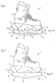
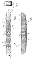
- FIGS. 1 and 2 each show one known inline skate 1, consisting of a shoe 2 with a under the sole of the shoe 2 fixed holding device 3.
- the holding device 3 is used for receiving and storing the rollers 4 and the Heel area of the shoe arranged brake 5.
- For storing the rollers 4 and the brake 5 is the holding device in the lower area with corresponding suitable bearings or bearing axles 6.
- the area under the rollers 4 is of the inline skate 1 each with an embodiment of an inventive cover device extending in the running direction L of the rollers 4 7 provided.
- the cover device 7 shown in Fig. 1 is here from one to the subsurface, essentially arcuate, one tread 16 forming foot-appropriate movement sequence, rail-shaped cover element 8, which at the respective ends 9 has a fastening device 10 formed.
- the fastener 10 is designed in the form of a terminal strip on the front or rear roller 4 is clamped.
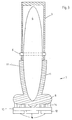
- FIG. 3 Shown sectional view of a covering device 7 according to the invention recognize, are the fastening devices forming the cover device 7 10 and the cover element 8 are formed in one piece.
- a covering device 7 has a fastening device 10 which is clamped onto all rollers 4 of the inline skate 1.
- the covering device 7 made of plastic or another suitable lightly elastic, resilient material made and can also not here have shown deposits. It is also possible to cover device 7 To be designed so that it can be clamped onto the holding device 3 or is held by this in a suitable manner.
- the cover member 8 is on its to Side of the tread 16 facing the surface with a coating 12 Mistake.
- the coating 12 is to prevent it from slipping when walking prevent and ensure a safe stand from a non-slip Material, for example made of rubber. It can for the coating 12
- an abrasion-resistant rubber material is used, especially when walking on smooth surfaces, such as parquet, marble and the like, no corresponding rubber markings on the surface leave.
- the cover 7 between the cover 8 and the coating 12 is provided with differently designed webs 14. These webs 14 are designed similar to a spring or a damper, so that the ankles are relieved when walking and thus protected.
- the Crosspieces 14 can be formed directly with the cover element 8 or - as shown in Fig. 3 - are subsequently attached to the cover member 8, for example screwed, inserted or glued.
- the coating 12 replaceable like a shoe sole or exchangeable.
- a fastening device 15 is provided, to which the coating 12 is glued, for example or can be screwed on and thus, for example, when worn or wear replaced or replaced similar to a shoe sole can be.
- the fastening device 15 can also be made in one piece the cover element 8 or the webs 14 or, for example attached to this with a screw, plug or adhesive connection will. There is also the possibility of using the fastening device 15 the webs 14 and the cover 8 in the form of a double rail.
- the covering device 7 Due to the curved configuration of the outsole 16 of the cover element 8 the covering device 7 makes it easier to roll the foot when walking and allows a movement that is appropriate for the foot.
- Fig. 1 Embodiment results in particular from the between the two fastening devices 10 formed resilient area 13 the Possibility of further suspension, damping that further improves facilitated and joint-friendly walking allowed.
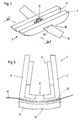
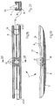
- FIG. 4 shows a perspective view of a further exemplary embodiment a covering device according to the invention 7.
- this covering device 7 are the covering element 8 providing the tread 16 and the as Fastening device 10 formed in one piece in the form of a terminal strip open, substantially U-shaped cross-section having a hollow profile educated.
- the fastening device 10 is thus spaced apart opposite, essentially in the running direction L of the rollers parallel edges 11 that taper towards each other and so a clamping of the fastening device 10 in the positioned state enable, as in particular with reference to the sectional view in FIG. 5 shown.
- the cover 7 has on it Different positioning and fixing elements 17 on the inside in pairs, to align the cover device 7 when positioning below the Inline skates 1 serve and at the same time support fixing the rollers 4 can.
- the positioning and fixing elements 17 given the greatest possible stiffening of the covering device 7.
- the covering device 7 according to FIGS. 4 and 5 has another one in the center the fastening device 18 attached in the form of a Volume 19 on.
- the band 19 is centered in the area of the cover element 8 arranged, transverse to the direction L of the rollers 4 opening 20 led. For additional fastening of the covering device 7 the band 19 then over the shoe not shown in FIGS. 4 and 5 Inline skates 1 placed and finally largely positively fixed.
- the cover device 7 shown in FIGS. 4 and 5 has non-slip Inserts 21, which are interchangeable and changed, for example, when worn can be.
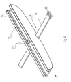
- FIG. 6 shows a perspective view of a further exemplary embodiment a covering device 7 according to the invention.
- Cover device 7 has the cover device 7 shown in FIG. 6 positioning / fixing elements likewise arranged in the center of the covering device 7 17 on.
- An additional fastening means 18 is also here Band 19 is provided, which can be closed with a buckle 22 is provided.
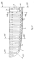
- FIG. 7 shows the covering device 7 according to FIG. 6 in a front view.
- the covering device 7 on the symbolically represented rollers 4 Inline skates 1, not shown here, below the holding device 3 put on and clamped.
- the Edges 11 of the covering device 7 each with the inside of the through Protrusions 24 surrounding projections 24 Mistake.
- the projections 24 form the Cover device 7 together with the edges 11 and the substantially U-shaped cross section of the hollow profile of the covering device 7 on the Rollers 4 pincer-like fastening device.
- FIGS. 9 and 10 Inserts 21 made of non-slip material, such as rubber or the like, can be used, for example, by gluing or pressing. As in 9 and 10, the insert 21 on the part of the tread 16 with provided with a profile 25, the slip and stability further enlarged.
- FIG. 12 shows a plan view of a further exemplary embodiment of a Covering device 7, the positioning and / or centrally arranged on its inside Has fixing elements 17. As with the cut view 13, the positioning and / or fixing elements 17 in Form of ribs of different lengths.
- the cover 7 has below the substantially center the covering device 7 arranged positioning and / or fixing elements 17 an opening 20 for the passage of a tape 19, not shown here an additional fastener 18.
- 15 to 17 is another embodiment of a Cover device 7 shown.
- the edges 11 and the cover 8 of the Cover device 7 are here on their inside with lamella-like Recesses 26 provided, on the one hand, the stability and flexibility of the Increase cover device 7 and secondly its own weight to reduce.
- FIG. 18 to 20 show another embodiment of a Cover device 7.
- This has, as in particular with reference to that in FIG. 19 shown cut view recognizable, in a central region of the Edges 11 have a recess 27 extending in the running direction L.
- this cover device 7 in particular for inline skates with a provided between the two middle rollers, on the holding device trained slide area, for example for sliding on a Railings or the like, suitable.
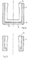
- Fig. 21 shows a part of a in a sectional view Cover device 7 according to FIGS. 15 to 17.
- FIG. 22 to 25 show different sectional views accordingly the section lines drawn in FIG. 21.
- auxiliary lines are the opposing positioning and / or Fixing elements 17 widen conically towards the opening of the hollow profile educated.
- the positioning and / or fixing elements 17 thereby receive one Dual function.
- they serve to position the Cover device 7 under the inline skate 1. Due to its conical shape the rollers 4 of the inline skate 1 are clamped at the same time and so the attachment of the cover device 7 supports.
- the covering device in the area below the positioning and / or Fixing elements 17 an opening 20 for carrying out a not here illustrated band 19 as an additional fastener 18.
- the distance between the opposing positioning and / or Fixing elements 17 is particularly advantageously dimensioned so that this the width of an edge 11 with projection 24 of a covering device 7 corresponds.
- two covering devices 7, for example for Transport can be easily inserted into each other.
- the two cover devices advantageously one inside the other clamped.
Landscapes
- Footwear And Its Accessory, Manufacturing Method And Apparatuses (AREA)
- Seal Device For Vehicle (AREA)
- Centrifugal Separators (AREA)
- Glass Compositions (AREA)
Abstract
Um eine Abdeckvorrichtung für die Rollen von Rollschuhen, insbesondere von Inlineskates, bereitzustellen, mit der sich Einschränkungen hinsichtlich der Bewegungsfreiräume und Beweglichkeit reduzieren lassen, und die gleichzeitig behinderungsfreie Gehbewegungen ermöglicht, wird mit der vorliegenden Erfindung eine Abdeckvorrichtung (7) für die Rollen (4) von Rollschuhen (1), insbesondere von Inlineskates, bestehend aus wenigstens einem mit wenigstens einer Befestigungseinrichtung (10) zumindest unter den Rollen (4) positionierbaren Abdeckelement (8) vorgeschlagen, die dadurch gekennzeichnet ist, daß das Abdeckelement (8) in positioniertem Zustand eine sich in Laufrichtung (L) der Rollen (4) erstreckende, im wesentlichen bogenförmig zum Untergrund verlaufende, beim Gehen einen fußgerechten Bewegungsablauf ermöglichende Lauffläche (16) aufweist. <IMAGE>In order to provide a covering device for the rollers of roller skates, in particular inline skates, with which restrictions with regard to freedom of movement and mobility can be reduced and which at the same time enables unimpeded walking movements, the present invention provides a covering device (7) for the rollers (4). of roller skates (1), in particular of in-line skates, consisting of at least one cover element (8) which can be positioned at least under the rollers (4) with at least one fastening device (10), which is characterized in that the cover element (8) is in the positioned state has running surface (16) which extends in the running direction (L) of the rollers (4) and runs essentially in an arc shape to the ground and enables a movement sequence which is appropriate for the foot when walking. <IMAGE>
Description
Die vorliegende Erfindung betrifft eine Abdeckvorrichtung für die Rollen von Rollschuhen, insbesondere von Inlineskates, bestehend aus Wenigstens einem mit wenigstens einer Befestigungseinrichtung zumindest unter den Rollen positionierbaren Abdeckelement.The present invention relates to a covering device for the rolls of Roller skates, especially inline skates, consisting of at least one with at least one fastening device that can be positioned at least under the rollers Cover element.
Es sind verschiedene Typen von Rollschuhen aus dem Sport- und Freizeitbedarf bekannt, beispielsweise sogenannte Rollerskates, Inlineskates, auch Kufenrollschuhe genannt, und dergleichen, die sich hinsichtlich Ausgestaltung und Anordnung insbesondere der Rollen unterscheiden. Nach dem Anschnallen bzw. Anziehen ermöglichen diese ein Fahren auf entsprechend geeigneten Untergründen. Auf ungeeigneten Untergründen, beispielsweise auf Kies, Sand, Pflastersteinen und dergleichen ist ein bestimmungsgemäßes Fahren erschwert bzw. unmöglich und kann darüber hinaus zu Beschädigungen der Rollschuhe führen. Desweiteren ist das Fahren mit entsprechenden Rollschuhen in vielen Bereichen, beispielsweise in Parkanlagen, Einkaufspassagen und in Gebäuden, wie beispielsweise Supermärkten, Geschäften und dergleichen, verboten, unter anderem aus versicherungstechnischen Gründen. Der Benutzer entsprechender Rollschuhe ist dadurch also entweder in seinen Bewegungsfreiräumen eingeschränkt oder ist gezwungen, stets ein Paar normaler Ersatzschuhe mit sich zu führen.There are different types of roller skates for sport and leisure needs known, for example so-called roller skates, inline skates, also skate roller skates called, and the like, which are in terms of design and the arrangement, in particular of the roles. After buckling up or tightening these make it possible to drive on suitable ones Substrates. On unsuitable surfaces, for example on gravel, sand, Paving stones and the like makes driving as intended difficult or impossible and can also damage the Guide roller skates. Furthermore, driving with appropriate roller skates in many areas, for example in parks, shopping arcades and in buildings such as supermarkets, shops and the like, prohibited, among other things for insurance reasons. The user Corresponding roller skates are therefore either in their freedom of movement restricted or forced to always be a pair normal Carry spare shoes with you.
Um ein Tragen der Rollschuhe auch auf ungeeigneten Untergründen und in Bereichen, in denen eine Benutzung der Rollschuhe nicht zulässig ist, zu ermöglichen, ist beispielsweise aus der DE 30 16 602 A1 ein Untersatz zum Festsetzen der Rollen eines Roller-Skates bekannt, der im montierten Zustand ein Drehen der Rollen unterbindet. Der Untersatz ist im wesentlichen plattenförmig ausgebildet und läßt sich lösbar durch Festklemmen an deren Lauffläche unter diesen befestigen. Der Untersatz bildet zwischen den Rollen einen im wesentlichen ebenen und starren Auflagebereich, so daß sichere und behinderungsfreie Gehbewegungen, insbesondere da ein Abrollen des Fußes beim Gehen verhindert wird, mit dieser Abdeckvorrichtung nicht möglich ist.In order to wear the roller skates even on unsuitable surfaces and in areas in which the use of roller skates is not permitted, is for example from DE 30 16 602 A1 a base for fixing the roles of a roller skate known in the assembled state Prevents the rollers from rotating. The base is essentially plate-shaped trained and can be releasably by clamping on the tread under attach this. The base essentially forms one between the rollers flat and rigid support area, so that safe and unobstructed Walking movements, especially since the foot rolls when walking is prevented, is not possible with this cover.
Der vorliegenden Erfindung liegt die Aufgabe zugrunde, eine gattungsgemäße Abdeckvorrichtung für die Rollen von Rollschuhen, insbesondere von Inlineskates, bereitzustellen, mit der sich Einschränkungen hinsichtlich der Bewegungsfreiräume und der Beweglichkeit reduzieren und damit die Verwendbarkeit vergrößern lassen, und die gleichzeitig behinderungsfreie und gelenkschonende Gehbewegungen mit den Rollschuhen ermöglicht.The present invention has for its object to provide a generic covering device for the roles of roller skates, especially inline skates, with which restrictions in terms of freedom of movement and mobility can be reduced and thus the usability can be increased, and at the same time handicap-free and joint-friendly walking movements with the Allows roller skates.
Zur technischen Lösung dieser Aufgabe wird eine Abdeckvorrichtung für die Rollen von Rollschuhen, insbesondere von Inlineskates, bestehend aus wenigstens einem mit wenigstens einer Befestigungseinrichtung zumindest unter den Rollen positionierbaren Abdeckelement vorgeschlagen, bei der das Abdeckelement in positioniertem Zustand eine sich in Laufrichtung der Rollen erstreckende, im wesentlichen bogenförmig zum Untergrund verlaufende, beim Gehen einen fußgerechten Bewegungsablauf ermöglichende Lauffläche aufweist.For the technical solution to this problem, a cover device for the rollers of roller skates, in particular inline skates, is proposed, consisting of at least one cover element that can be positioned at least under the rollers with at least one fastening device, in which the cover element in the positioned state extends in the running direction of the rollers, in has a running surface that is essentially arched to the ground and enables walking to be performed while walking.
Unter einem fußgerechten Bewegungsablauf im Sinne der vorliegenden Erfindung werden insbesondere aufgrund anatomischer Gegebenheiten des menschlichen Stütz- und Bewegungsapparates vorgegebene Bewegungen verstanden, im vorliegenden Fall ein insbesondere gelenkschonendes und ermüdungsfreies Abrollen des Fußes.Under a foot-appropriate movement in the sense of the present invention are especially due to anatomical conditions of the human support and musculoskeletal system predetermined movements understood, in the present case a joint-friendly and fatigue-free Unrolling the foot.
Die erfindungsgemäße Abdeckvorrichtung läßt sich im Bedarfsfall so unter den Rollen eines entsprechenden Rollschuhs, beispielsweise einem sogenannten Inlineskate, positionieren, daß sich das Abdeckelement zwischen den Laufflächen der Rollen und dem Untergrund befindet. Dabei ist es wesentlich, daß ein direkter Kontakt der Laufrollen mit dem Untergrund verhindert wird. The cover device according to the invention can if necessary under the Rolling a corresponding roller skate, for example a so-called Inline skate, position that the cover element between the treads the rollers and the underground. It is essential that a direct contact of the rollers with the ground is prevented.
Mit einem mit einer entsprechenden Abdeckvorrichtung versehenen Rollschuh, insbesondere einem Inlineskate, ist eine normale Fortbewegung, das heißt ein normales Gehen bzw. Laufen wie mit einem herkömmlichen Schuh möglich. Damit sind insbesondere zum Fahren ungeeignete Untergründe, wie beispielsweise Matsch, Kiesel, Sand, Pflastersteine, Treppen und dergleichen mühelos, sicher und ohne Wechsel des Schuhwerks passierbar.With a roller skate provided with an appropriate covering device, inline skating in particular is normal locomotion, that is, one normal walking or running as possible with a conventional shoe. This makes surfaces unsuitable for driving, such as Mud, pebbles, sand, paving stones, stairs and the like effortlessly, passable safely and without changing footwear.
Dem Aufenthalt und dem Betreten von Plätzen bzw. Gebäuden auf bzw. in denen der Gebrauch von Rollschuhen aufgrund eines erhöhten Verletzungsrisikos nicht gestattet ist, steht im Prinzip bei Verwendung der erfindungsgemäßen Abdeckvorrichtung nichts mehr im Wege.The stay and entering places or buildings on or in those who use roller skates because of an increased risk of injury is not permitted, is in principle when using the invention Cover device nothing in the way.
Darüber hinaus entfällt - wie bereits erläutert - das Mitführen von geeignetem Ersatzschuhwerk und damit ferner das ansonsten notwendige mühsame Tragen der Rollschuhe. Durch eine unter den Rollen positionierte Abdeckvorrichtung werden dabei insbesondere beim Passieren ungeeigneter Untergründe die Rollen der entsprechenden Sport- und Freizeitschuhe geschont und vor Beschädigungen geschützt.In addition - as already explained - there is no need to carry suitable equipment Replacement footwear and thus the otherwise tedious wearing the roller skates. Through a covering device positioned under the rollers are especially when passing unsuitable surfaces Rolls of the corresponding sports and leisure shoes are spared and protected from damage protected.
Bei der erfindungsgemäßen Abdeckvorrichtung ist ein für den jeweiligen Rollschuh geeignet ausgestaltetes Abdeckelement mit einer für den jeweiligen Rollschuh geeigneten Befestigungseinrichtung jeweils an diesem überaus einfach fixierbar. Durch die gebogene Form der Lauffläche wird dabei das Abrollen des Fußes beim Gehen mit einem mit der entsprechenden erfindungsgemäßen Abdeckvorrichtung versehenen Rollschuh erleichtert. Darüber hinaus wird durch die gebogene Form der Lauffläche des Abdeckelementes eine leicht federnde Wirkung erzielt, die insbesondere beim Gehen leicht dämpfend wirkt und so ein gelenkschonendes Gehen ermöglicht.In the cover device according to the invention is one for the respective roller skate suitably designed cover element with one for each Suitable for roller skate fastener on this extremely easy fixable. Due to the curved shape of the tread, the unrolling becomes of the foot when walking with one with the corresponding invention Covering provided roller skate relieved. Furthermore is a light due to the curved shape of the tread of the cover achieves a springy effect, which has a slightly dampening effect, especially when walking and thus enables walking that is easy on the joints.
Die Abdeckvorrichtung kann dabei die sich in Laufrichtung erstreckende, im wesentlichen bogenförmig zum Untergrund verlaufende, beim Gehen einen fußgerechten Bewegungsablauf ermöglichende Lauffläche gemäß einem Vorschlag der Erfindung sowohl fest aufweisen, als auch diese erst beim Positionieren ausbilden. Dazu kann die Abdeckvorrichtung beispielsweise elastisch verformbar und spannbar sein. Ebenso kann die Abdeckvorrichtung faltbar sein und zum Beispiel beim bzw. nach dem Auseinanderfalten die erfindungsgemäße Lauffläche aufweisen.The covering device can extend in the running direction essentially arched to the ground, one when walking Walking surface according to a suggestion, which enables foot-appropriate movement the invention both have fixed, and this only when positioning form. For this purpose, the covering device can be elastic, for example be deformable and tensionable. The cover device can also be folded and, for example, when or after unfolding the have tread according to the invention.
Gemäß einem vorteilhaften Vorschlag der Erfindung ist die Bogenform der Lauffläche des Abdeckelementes einstellbar, vorzugsweise variabel einstellbar. Damit läßt sich die Lauffläche individuellen Bedürfnissen hinsichtlich des Bewegungsablaufes anpassen. So kann beispielsweise der Krümmungsgrad des Bogens variiert werden oder es können verschiedene Bogenformen, beispielsweise konvexe und konkave, kombiniert werden.According to an advantageous proposal of the invention, the arc shape is the Running surface of the cover element adjustable, preferably variably adjustable. This allows the tread to meet individual needs with regard to the movement sequence to adjust. For example, the degree of curvature of the Arc can be varied or different arc shapes, for example convex and concave.
Gemäß einer weiteren besonders vorteilhaften Ausgestaltung der Erfindung ist zumindest das Abdeckelement der Abdeckvorrichtung elastisch verformbar ausgebildet. Dadurch läßt sich eine weitere Federung und Dämpfung erzielen, die so ein gelenkschonendes und weitestgehend ermüdungsfreies Gehen ermöglicht.According to a further particularly advantageous embodiment of the invention at least the cover element of the cover device is elastically deformable educated. This allows further suspension and damping to be achieved, which enables walking that is easy on the joints and largely fatigue-free.
Vorteilhafterweise ist das Abdeckelement schienenförmig ausgebildet, so daß durch ein entsprechend positioniertes Abdeckelement der direkte Kontakt zwischen den Laufflächen mehrerer Rollen und dem Untergrund verhindert ist. Die Schiene ist dabei vorteilhafterweise entsprechend dem durch die an einem Rollschuh angeordneten Rollen vorgegebenen Laufflächenbereich angepaßt, das heißt beispielsweise bei einem Inlineskate, bei dem die Rollen in einer Reihe hintereinander angeordnet sind, daß das schienenförmige Abdeckelement sich in Laufrichtung der Rollen erstreckend im wesentlichen gerade verläuft.Advantageously, the cover element is rail-shaped, so that through a suitably positioned cover element the direct contact between the running surfaces of several rollers and the surface is prevented. The Rail is advantageously according to the one on Roller skates arranged rollers adapted to the given tread area, that means for example with an inline skate, in which the roles in one Row are arranged one behind the other that the rail-shaped cover element extending essentially straight in the direction of the rollers.
Gemäß einer weiteren besonders vorteilhaften Ausgestaltung der Erfindung ist zumindest die Lauffläche des Abdeckelementes wenigstens teilweise rutschfest ausgebildet.According to a further particularly advantageous embodiment of the invention at least the tread of the cover element at least partially non-slip educated.
Das Abdeckelement kann gemäß einer weiteren vorteilhaften Ausgestaltung der Erfindung mit wenigstens einer entsprechend geeigneten Beschichtung oder einem Belag versehen sein, der beispielsweise aus Gummi, Kautschuk und dergleichen bestehen kann. Vorteilhafterweise sind der entsprechende Belag- bzw. die Beschichtung dabei ähnlich einer Schuhsohle profiliert ausgebildet. Durch eine derartig ausgestaltete Oberfläche des Abdeckelementes wird einerseits die Bodenhaftung und damit die Sicherheit beim Gehen vergrößert, andererseits eine weitere gelenkschonende Dämpfung erzielt. Ähnlich einer Schuhsohle ist die Beschichtung gemäß einem weiteren vorteilhaften Vorschlag der Erfindung auswechselbar ausgestaltet, so daß insbesondere bei Abnutzung und Verschleiß der Beschichtung diese erneuert werden kann. In einer weiteren, besonders vorteilhaften Ausgestaltung weist das Abdeckelement im Laufsohlenbereich wenigstens einen rutschfesten Einsatz, ein sogenanntes Pad, vorzugsweise aus Gummi und dergleichen auf. Vorteilhafterweise ist dieser Einsatz ebenfalls austauschbar, so daß eine Erneuerung bei Abnutzung und Verschleiß des Einsatzes als auch eine Anpassung und Abstimmung des Einsatzes an verschiedene Untergründe gegeben ist. Der Einsatz kann vorteilhafterweise eingepreßt oder eingeklebt sein und beispielsweise aus einem speziellen Kunststoff bestehen. Damit wird eine Zwei-Komponenten-Laufsohle gebildet, die ein sicheres Fortbewegen auch auf nassen, glatten und polierten Untergründen erlaubt.According to a further advantageous embodiment, the cover element can of the invention with at least one correspondingly suitable coating or be provided with a covering made, for example, of rubber, rubber and the like can exist. The corresponding ones are advantageous Covering or the coating is profiled like a shoe sole. Through such a surface of the cover element on the one hand, grip and thus safety when walking is increased, on the other hand, a further joint-friendly damping is achieved. Similar to one The sole of the shoe is the coating according to a further advantageous proposal the invention designed interchangeable, so that in particular Wear and tear of the coating this can be renewed. In The cover element has a further, particularly advantageous embodiment at least one non-slip insert in the outsole area, a so-called Pad, preferably made of rubber and the like. Advantageously this insert is also interchangeable, so that renewal when worn and wear of the insert as well as adjustment and tuning use on different surfaces. The stake can advantageously be pressed or glued and, for example, from made of a special plastic. This creates a two-component outsole formed, which is a safe movement even on wet, smooth and polished surfaces allowed.
In einer weiteren besonders vorteilhaften Ausgestaltung der Erfindung ist die Abdeckvorrichtung zum Positionieren des Abdeckelementes mittels der Befestigungseinrichtung festklemmbar, vorteilhafterweise an den Rollen, der Rollenhalterung, den Rollenlagern oder dem Rollschuh. Selbstverständlich kann das Abdeckelement mittels der Befestigungseinrichtung auch in anderer geeigneter Art und Weise befestigt werden. Dazu kann beispielsweise die Befestigungseinrichtung angeschraubt, aufgesteckt oder sonstwie an entsprechend am Rollschuh ausgebildeten Vorrichtungen angeschraubt bzw. aufgesteckt werden.In a further particularly advantageous embodiment of the invention, the Cover device for positioning the cover element by means of the fastening device clampable, advantageously on the rollers, the Roller holder, the roller bearings or the roller skate. Of course you can the cover element by means of the fastening device also in another suitable Way to be attached. For this purpose, the fastening device can, for example screwed, plugged on or in some other way Devices screwed on or attached to the roller skate will.
Gemäß einer weiteren besonders vorteilhaften Ausgestaltung der Erfindung ist die Befestigungseinrichtung als Klemmleiste ausgebildet, die beispielsweise seitlich auf die Rollen aufgeklemmt werden kann. In einer besonders vorteilhaften Ausgestaltung ist die Klemmleiste ein offenes Hohlprofil, das vorzugsweise einen im wesentlichen C- oder U-förmigen Querschnitt aufweist. Vorteilhafterweise weist die Befestigungseinrichtung einander beabstandet gegenüberstehende, im wesentlichen in Laufrichtung der Rollen parallel verlaufende Kanten auf, die konisch aufeinander zulaufen und so ein Festklemmen der Befestigungseinrichtung ermöglichen. According to a further particularly advantageous embodiment of the invention the fastening device is designed as a terminal strip, for example can be clamped laterally on the rollers. In a particularly advantageous The terminal strip is an open hollow profile, which is preferred has a substantially C or U-shaped cross section. Advantageously the fastening device has mutually spaced, essentially parallel in the running direction of the rollers Edges that taper towards each other and thus stick enable the fastening device.
Gemäß einem weiteren Vorschlag der Erfindung ist die Befestigungseinrichtung so ausgebildet, daß diese variabel befestigbar ist. Dadurch läßt sich die Abdeckvorrichtung an verschiedenen Rollschuhen positionieren und ist insbesondere bei unterschiedlichen Rollenabständen an diese anpaßbar, beispielsweise für Kinderschuhe und Sonderanfertigungen bzw. -modelle mit zum Beispiel größerem Rollenabstand.According to a further proposal of the invention, the fastening device designed so that it can be attached variably. This allows the Position cover device on different roller skates and is special adaptable to these at different roller spacings, for example for children's shoes and special designs or models with, for example larger roller distance.
Gemäß einem weiteren Vorschlag der Erfindung nimmt die positionierte Abdeckvorrichtung die Rollen des Rollschuhs im wesentlichen formschlüssig auf. Dadurch wird zum einen der Halt der Abdeckvorrichtung vergrößert und zum anderen werden die Rollen des Rollschuhs vor Beschädigungen, beispielsweise der Rollenlager durch Sand, Wasser und dergleichen, weitestgehend geschützt.According to a further proposal of the invention, the positioned covering device takes the roles of the roller skate essentially form-fitting. On the one hand, this increases the hold of the covering device and, on the other others the roles of the roller skate from damage, for example the roller bearings are largely protected by sand, water and the like.
Gemäß einer vorteilhaften Ausgestaltung der Erfindung sind die Befestigungseinrichtungen und das Abdeckelement einteilig ausgebildet. Damit läßt sich die Abdeckvorrichtung überaus einfach und wirtschaftlich fertigen, insbesondere da entsprechende Montagearbeiten entfallen können. Zusätzlich wird durch die einteilige Ausbildung des Abdeckelementes und der Befestigungseinrichtung eine wesentliche größere Stabilität und Haltbarkeit der erfindungsgemäßen Abdeckvorrichtung erzielt.According to an advantageous embodiment of the invention, the fastening devices and the cover element is formed in one piece. So that the Manufacture cover device extremely easily and economically, in particular since corresponding assembly work can be omitted. In addition, by the one-piece design of the cover element and the fastening device a much greater stability and durability of the invention Cover device achieved.
Gemäß einem besonders vorteilhaften Vorschlag der Erfindung weist die Abdeckvorrichtung als Befestigungsmittel ein Band auf. Vorteilhafter ist das Band elastisch, beispielsweise aus Gummi oder dergleichen, so daß ein leichtes und einfaches Befestigen der Abdeckvorrichtung gegeben ist. In einer besonders vorteilhaften Ausgestaltung der Erfindung weist das Band zwei Enden auf. Damit ist das Befestigen noch weiter vereinfacht, da die Abdeckvorrichtung einfach angebunden werden kann, beispielsweise zur Sicherung. Vorteilhafterweise weist das Band einen Klettverschluß auf bzw. ist ein Klettband.According to a particularly advantageous proposal of the invention, the covering device tape as a fastener. The tape is more advantageous elastic, for example made of rubber or the like, so that a light and easy attachment of the cover is given. In one particularly advantageous embodiment of the invention, the band has two ends. Fastening is thus further simplified since the covering device can be easily connected, for example for security purposes. Advantageously the band has a Velcro fastener or is a Velcro.
In einer besonders vorteilhaften Ausgestaltung weist die Abdeckvorrichtung eine Öffnung zur Führung des Bandes auf, die vorzugsweise quer zur Laufrichtung der Rollen verläuft. Gemäß einem vorteilhaften Vorschlag der Erfindung ist die Öffnung in einem Bereich unter den Rollen angeordnet. Vorteilhafterweise ist die Öffnung eine Durchgangsöffnung, also im wesentlichen schlitzförmig ausgebildet. Die Öffnung ist gemäß einer weiteren vorteilhaften Ausgestaltung der Erfindung mittig der Abdeckvorrichtung angeordnet. Durch eine derartige Ausgestaltung läßt sich die Abdeckvorrichtung überaus einfach und schnell befestigen bzw. sichern, so daß auch beim Gehen in schwierigstem Gelände die Abdeckvorrichtung fixiert bleibt und ein guter Halt gewährleistet wird. Gleichzeitig wird das Band geschützt, da dieses nicht den Untergrund berührt und so nicht durchscheuern kann.In a particularly advantageous embodiment, the covering device an opening for guiding the tape, which is preferably transverse to The running direction of the rollers runs. According to an advantageous proposal of the Invention, the opening is arranged in an area under the rollers. The opening is advantageously a through opening, that is to say in essentially slit-shaped. The opening is according to another advantageous embodiment of the invention arranged in the center of the covering device. With such a configuration, the covering device can be Attach or secure extremely easily and quickly, so that even when walking the cover device remains fixed in difficult terrain and a good one Hold is guaranteed. At the same time, the tape is protected because it is not touches the surface and cannot rub through.
Gemäß einem weiteren vorteilhaften Vorschlag der Erfindung ist die Abdeckvorrichtung federnd ausgebildet. Dadurch lassen sich stoßdämpfende Eigenschaften weiter verbessern und so das Gehen mit mit einer erfindungsgemäßen Abdeckvorrichtung versehenen Rollschuhen weiter erleichtern und somit komfortabler gestalten. Die Abdeckvorrichtung ist vorteilhafterweise aus einem leicht elastischen, federnden Material gefertigt, vorzugsweise aus Kunststoff. Gemäß einem weiteren vorteilhaften Vorschlag der Erfindung weist die Abdeckvorrichtung wenigstens eine elastische ausgebildete, formstabilisierende Einlage auf. Diese kann beispielsweise in vorteilhafter Weise aus Federstahlblech gefertigt sein. Dadurch wird sichergestellt, daß die stoßdämpfenden und federnden Wirkungen der Abdeckvorrichtung sowie ein sicheres Festklemmen auch über längere und intensivere Benutzungszeiträume gewährleistetwerden.According to a further advantageous proposal of the invention, the covering device springy. This allows shock-absorbing properties continue to improve and so walking with an inventive Covering provided roller skates further facilitate and thus Make it more comfortable. The covering device is advantageously made of one slightly elastic, resilient material, preferably made of plastic. According to a further advantageous proposal of the invention, the Cover device at least one elastic, shape-stabilizing Insert on. This can advantageously be made of spring steel sheet, for example be made. This ensures that the shock absorbing and resilient effects of the cover device as well as secure clamping also be guaranteed over longer and more intensive periods of use.
Gemäß einem weiteren, besonders vorteilhaften Vorschlag der Erfindung weist die Abdeckvorrichtung auf der Innenseite Positionier- und Fixierelemente auf. Diese dienen zum Ausrichten der Abdeckvorrichtung beim Positionieren und unterstützen gleichzeitig die Befestigung derselben.According to a further, particularly advantageous proposal of the invention the cover device on the inside positioning and fixing elements. These are used to align the cover device when positioning and support the attachment of the same.
Die Positionier- und Fixierelemente sind vorteilhafterweise als paarweise einander gegenüberstehende Rippen ausgebildet, die vorzugsweise unterschiedlich lang ausgebildet sind und so einerseits der Rollenkontur anpaßbar sind, andererseits eine gezielte Versteifung des Abdeckelementes bereitstellen.The positioning and fixing elements are advantageously in pairs opposite ribs formed, which are preferably different are long and so on the one hand the roller contour can be adjusted, on the other hand provide a targeted stiffening of the cover element.
Gemäß einem weiteren Vorschlag der Erfindung ist die Abdeckvorrichtung nachrüstbar, so daß alle bekannten Rollschuhe nachträglich aufgrund der vorteilhaften variablen Ausgestaltung der Abdeckvorrichtung mit dieser ausgestattet werden können. According to a further proposal of the invention, the covering device can be retrofitted so that all known roller skates can be retrofitted due to the advantageous variable configuration of the cover device equipped with this can be.
Gemäß einer weiteren vorteilhaften Ausgestaltung der Erfindung ist die Abdeckvorrichtung schwenkbar an einem Rollschuh befestigbar. Damit wird die Möglichkeit geschaffen, die Abdeckvorrichtung durch eine einfache Schwenkbewegung bzw. ein Herunterklappen, Umklappen, Drehen oder dergleichen zu aktivieren, so daß das Abdeckelement den direkten Kontakt zwischen den Rollen und dem Untergrund unterbindet. Eine entsprechende Abdeckvorrichtung kann beispielsweise mit einem Ende am hinteren Ende des Rollschuhs, beispielsweise an der Rollenhalterung, angelenkt sein und mit dem anderen Ende bei Nichtbenutzung in geeigneter Art und Weise, beispielsweise am Schuh des Rollschuhs, lösbar fixierbar sein. Bei Bedarf wird die Abdeckvorrichtung vom Schuh des Rollschuhs gelöst und durch eine einfache Schwenkbewegung unter den Rollen des Rollschuhs in erfindungsgemäßer Art und Weise positioniert. Dabei kann die erfindungsgemäße Lauffläche beispielsweise beim Positionieren ausgebildet werden oder bereits fest an der Abdeckvorrichtung vorhanden sein. Eine derartige Ausgestaltung hat darüber hinaus den Vorteil, daß die Ausgabeeinrichtung nicht verlorengehen kann und stets zur Verwendung bereitsteht. Gemäß einer weiteren vorteilhaften Ausgestaltung ist die erfindungsgemäße Abdeckvorrichtung an einem Rollschuh ausgebildet, so daß diese gezielt auf den entsprechenden Rollschuh ausgestaltet werden kann.According to a further advantageous embodiment of the invention, the covering device can be pivotally attached to a roller skate. With that the Possibility created the cover device by a simple swivel movement or a folding down, folding down, turning or the like activate so that the cover element makes direct contact between the Rolls and prevents the underground. A corresponding cover device can, for example, with one end at the rear end of the roller skate, for example, be articulated on the roll holder and with the other End when not in use in a suitable manner, for example on Shoe of the roller skate, be releasably fixable. If necessary, the cover device detached from the shoe of the roller skate and by a simple swivel movement under the rollers of the roller skate in the inventive manner and Positioned way. The tread according to the invention can for example be trained when positioning or already firmly on the cover to be available. Such a configuration also has the Advantage that the output device can not be lost and always for Use is ready. According to a further advantageous embodiment the covering device according to the invention formed on a roller skate, so that they are designed specifically for the corresponding roller skate can.
Gemäß einem weiteren vorteilhaften Vorschlag der Erfindung ist eine entsprechende Abdeckvorrichtung seitlich zwischen den Rollen eines entsprechenden Rollschuhs befestigbar. Weitere vorteilhafte Ausgestaltungen der Erfindung, die im wesentlichen bei Aktivierung eine Bewegung der Rollen verhindern, sind denkbar. So kann beispielsweise eine entsprechende Steckleiste mit ausgeformten Zapfen in beispielsweise in den Rollen ausgebildete Aussparungen eingreifen und diese so an einer Bewegung, insbesondere einem Drehen, hindern.According to a further advantageous proposal of the invention, there is a corresponding one Cover device laterally between the rollers of a corresponding Roller skates can be attached. Further advantageous refinements of the invention, which essentially prevent the rollers from moving when activated, are conceivable. For example, a corresponding header with molded Pins in recesses formed, for example, in the rollers intervene and thus prevent them from moving, in particular turning.
Weitere Vorteile und Merkmale der Erfindung ergeben sich aus der folgenden Beschreibung anhand der Figuren. Dabei zeigen:
- Fig. 1 und 2
- jeweils ein Ausführungsbeispiel einer an einem Inlineskate angebrachten Abdeckvorrichtung gemäß der vorliegenden Erfindung;
- Fig. 3
- eine teilweise geschnittene Ansicht durch eine an einem Inlineskate angebrachte Abdeckvorrichtung;
- Fig. 4
- eine perspektivische Ansicht eines weiteren Ausführungsbeispiels einer erfindungsgemäßen Abdeckvorrichtung;
- Fig. 5
- eine geschnittene Ansicht der Abdeckvorrichtung gemäß Fig. 4;
- Fig. 6
- eine perspektivische Ansicht eines weiteren Ausführungsbeispiels einer erfindungsgemäßen Abdeckvorrichtung;
- Fig. 7
- eine Vorderansicht der Abdeckvorrichtung gemäß Fig. 6;
- Fig. 8
- die Ansicht einer teilweise dargestellten Abdeckvorrichtung von unten;
- Fig. 9
- eine Ansicht von unten auf einen Einsatz für eine Abdeckvorrichtung gemäß Fig. 8;
- Fig. 10
- eine geschnittene Ansicht durch einen Einsatz gemäß Fig. 9;
- Fig. 11
- eine geschnittene Ansicht durch einen Teilbereich einer Abdeckvorrichtung gemäß Fig. 8;
- Fig. 12
- eine Draufsicht auf ein weiteres Ausführungsbeispiel einer erfindungsgemäßen Abdeckvorrichtung;
- Fig. 13
- eine geschnittene Ansicht der Abdeckvorrichtung gemäß Fig. 12;
- Fig. 14
- eine weitere geschnittene Ansicht der Abdeckvorrichtung gemäß Fig. 12;
- Fig. 15
- eine Draufsicht auf ein weiteres Ausführungsbeispiel einer erfindungsgemäßen Abdeckvorrichtung;
- Fig. 16
- eine geschnittene Ansicht der Abdeckvorrichtung gemäß Fig. 15;
- Fig. 17
- eine weitere geschnittene Ansicht der Abdeckvorrichtung gemäß Fig. 15;
- Fig. 18
- eine Draufsicht auf ein weiteres Ausführungsbeispiel einer erfindungsgemäßen Abdeckvorrichtung;
- Fig. 19
- eine geschnittene Ansicht der Abdeckvorrichtung gemäß Fig. 18;
- Fig. 20
- eine weitere geschnittene Ansicht der Abdeckvorrichtung gemäß Fig. 18;
- Fig. 21
- eine geschnittene Ansicht eines weiteren Ausführungsbeispiels
einer erfindungsgemäßen Abdeckvorrichtung ähnlich den Fig.
15
bis 17; - Fig. 22
- eine geschnittene Ansicht der Abdeckvorrichtung gemäß Fig. 21;
- Fig. 23
- eine geschnittene Ansicht der Abdeckvorrichtung gemäß Fig. 21;
- Fig. 24
- eine geschnittene Ansicht der Abdeckvorrichtung gemäß Fig. 21 und
- Fig. 25
- eine geschnittene Ansicht der Abdeckvorrichtung gemäß Fig. 21.
- 1 and 2
- in each case an embodiment of a covering device attached to an inline skate according to the present invention;
- Fig. 3
- a partially sectioned view through a cover device attached to an inline skate;
- Fig. 4
- a perspective view of another embodiment of a covering device according to the invention;
- Fig. 5
- a sectional view of the cover device of FIG. 4;
- Fig. 6
- a perspective view of another embodiment of a covering device according to the invention;
- Fig. 7
- a front view of the cover device of FIG. 6;
- Fig. 8
- the view of a partially shown cover device from below;
- Fig. 9
- a bottom view of an insert for a cover device according to FIG. 8;
- Fig. 10
- a sectional view through an insert according to FIG. 9;
- Fig. 11
- a sectional view through a portion of a cover device according to FIG. 8;
- Fig. 12
- a plan view of a further embodiment of a covering device according to the invention;
- Fig. 13
- a sectional view of the cover device of FIG. 12;
- Fig. 14
- another sectional view of the covering device according to FIG. 12;
- Fig. 15
- a plan view of a further embodiment of a covering device according to the invention;
- Fig. 16
- a sectional view of the cover device of FIG. 15;
- Fig. 17
- another sectional view of the covering device according to FIG. 15;
- Fig. 18
- a plan view of a further embodiment of a covering device according to the invention;
- Fig. 19
- a sectional view of the cover device of FIG. 18;
- Fig. 20
- another sectional view of the cover device according to FIG. 18;
- Fig. 21
- a sectional view of another embodiment of a covering device according to the invention similar to FIGS. 15 to 17;
- Fig. 22
- a sectional view of the cover device of FIG. 21;
- Fig. 23
- a sectional view of the cover device of FIG. 21;
- Fig. 24
- a sectional view of the cover device of FIG. 21 and
- Fig. 25
- a sectional view of the cover device of FIG. 21.
Die in den Fig. 1 und 2 dargestellten Ausführungsbeispiele zeigen jeweils einen
an sich bekannten Inlineskate 1, bestehend aus einem Schuh 2 mit einer
unter der Sohle des Schuhs 2 fest angeordneten Haltevorrichtung 3. Die Haltevorrichtung
3 dient zur Aufnahme und Lagerung der Rollen 4 und der im
Fersenbereich des Schuhs angeordneten Bremse 5. Zur Lagerung der Rollen 4
und der Bremse 5 ist die Haltevorrichtung im unteren Bereich mit entsprechend
geeigneten Lagern bzw. Lagerachsen 6 versehen.The embodiments shown in FIGS. 1 and 2 each show one
known inline skate 1, consisting of a
Wie in den Fig. 1 und 2 dargestellt, ist der unter den Rollen 4 befindliche Bereich
des Inlineskates 1 jeweils mit einem Ausführungsbeispiel einer erfindungsgemäßen,
sich in Laufrichtung L der Rollen 4 erstreckenden Abdeckvorrichtung
7 versehen. Die in Fig. 1 abgebildete Abdeckvorrichtung 7 wird hier
von einem eine zum Untergrund im wesentlichen bogenförmig verlaufende, einen
fußgerechten Bewegungsablauf ermöglichende Lauffläche 16 ausbildendes,
schienenförmiges Abdeckelement 8, welches an den jeweiligen Enden 9
eine Befestigungseinrichtung 10 aufweist, gebildet. Die Befestigungseinrichtung
10 ist hierbei in Form einer Klemmleiste ausgebildet, die auf der vorderen
bzw. hinteren Rolle 4 aufgeklemmt wird. Wie insbesondere in der in Fig. 3
dargestellten Schnittansicht einer erfindungsgemäßen Abdeckvorrichtung 7 zu
erkennen, sind die die Abdeckvorrichtung 7 bildenden Befestigungseinrichtungen
10 und das Abdeckelement 8 einteilig ausgebildet. Ferner ist in Fig. 3 zu
erkennen, daß die Abdeckvorrichtung 7 insbesondere im Bereich der Befestigungseinrichtung
10 einen im wesentlichen U-förmigen Querschnitt aufweist,
wobei die seitlichen Kanten 11 leicht geneigt sind, und sich so beim Anbringen
der Abdeckvorrichtung 7 im Bereich der Rollen 4 des Inlineskates 1 seitlich
an den Rollen 4 festklemmen. Das in Fig. 2 dargestellte Ausführungsbeispiel
einer Abdeckvorrichtung 7 weist eine Befestigungseinrichtung 10 auf, die
auf alle Rollen 4 des Inlineskates 1 aufgeklemmt wird. Zum Aufklemmen ist
die Abdeckvorrichtung 7 dazu aus Kunststoff oder einem anderen geeigneten,
leichtelastischen, federnden Material gefertigt und kann zusätzlich hier nicht
gezeigte Einlagen aufweisen. Ebenso ist es möglich, die Abdeckvorrichtung 7
so auszugestalten, daß diese auf die Haltevorrichtung 3 aufklemmbar ist bzw.
von dieser in geeigneter Weise gehalten wird.As shown in FIGS. 1 and 2, the area under the
Wie in den Fig. 1 bis 3 dargestellt, ist das Abdeckelement 8 auf seiner zum
Untergrund gerichteten Seite der Lauffläche 16 mit einer Beschichtung 12
versehen. Die Beschichtung 12 besteht, um ein Wegrutschen beim Gehen zu
verhindern und einen sicheren Stand zu gewährleisten, aus einem rutschfesten
Material, beispielsweise aus Gummi. Dabei kann für die Beschichtung 12 zum
Beispiel ein abriebfestes Gummimaterial verwendet, um so beim Gehen, insbesondere
auf glatten Untergründen, beispielsweise Parkett, Marmor und dergleichen,
keine entsprechenden Gummimarkierungen auf dem Untergrund zu
hinterlassen. Ferner ist in dem in Fig. 3 dargestellten Ausführungsbeispiel zu
erkennen, daß die Abdeckvorrichtung 7 zwischen dem Abdeckelement 8 und
der Beschichtung 12 mit verschieden ausgestalteten Stegen 14 versehen ist.
Diese Stege 14 sind ähnlich einer Feder oder einem Dämpfer ausgebildet, so
daß beim Gehen die Fußgelenke entlastet und somit geschont werden. Die
Stege 14 können direkt mit dem Abdeckelement 8 ausgebildet werden oder
- wie in Fig. 3 dargestellt - nachträglich am Abdeckelement 8 befestigt werden,
beispielsweise geschraubt, gesteckt oder geklebt. Zusätzlich ist - wie in
Fig. 3 dargestellt - die Beschichtung 12 ähnlich einer Schuhsohle austauschbar
bzw. auswechselbar ausgebildet. Dazu ist bei dem in Fig. 3 dargestellten
Ausführungsbeispiel zwischen den dämpfenden Stegen 14 eine Befestigungseinrichtung
15 vorgesehen, an die die Beschichtung 12 beispielsweise angeklebt
oder angeschraubt werden kann und somit zum Beispiel bei Abnutzung
bzw. Verschleiß ähnlich einer Schuhsohle ausgetauscht bzw. ausgewechselt
werden kann. Die Befestigungseinrichtung 15 kann dabei ebenfalls einteilig mit
dem Abdeckelement 8 bzw. den Stegen 14 ausgebildet sein oder beispielsweise
an diesen mit einer Schraub-, Steck- oder Klebverbindung befestigt
werden. Ebenso besteht die Möglichkeit, die Befestigungseinrichtung 15 mit
den Stegen 14 und dem Abdeckelement 8 in Form einer Doppelschiene auszugestalten.As shown in Figs. 1 to 3, the
Durch die gebogene Ausgestaltung der Laufsohle 16 des Abdeckelementes 8
der Abdeckvorrichtung 7 wird beim Gehen das Abrollen des Fußes erleichtert
und ein fußgerechter Bewegungsablauf ermöglicht. Beim dem in Fig. 1 dargestellten
Ausführungsbeispiel ergibt sich insbesondere durch den zwischen den
beiden Befestigungseinrichtungen 10 ausgebildeten federnden Bereich 13 die
Möglichkeit einer weiteren Federung, einer Dämpfung, die ein weiter verbessertes,
erleichtertes und gelenkschonendes Gehen gestattet.Due to the curved configuration of the
Fig. 4 zeigt eine perspektivische Ansicht eines weiteren Ausführungsbeispiels
einer erfindungsgemäßen Abdeckvorrichtung 7. Bei dieser Abdeckvorrichtung
7 sind das die Lauffläche 16 bereitstellende Abdeckelement 8 und die als
Klemmleiste ausgebildete Befestigungseinrichtung 10 einteilig in Form eines
offenen, im wesentlichen einen U-förmigen Querschnitt aufweisenden Hohlprofils
ausgebildet. Die Befestigungseinrichtung 10 weist somit einander beabstandet
gegenüberstehende, im wesentlichen in Laufrichtung L der Rollen
parallel verlaufende Kanten 11 auf, die konisch aufeinander zulaufen und so
im positionierten Zustand ein Festklemmen der Befestigungseinrichtung 10
ermöglichen, wie insbesondere anhand der geschnittenen Ansicht in Fig. 5
dargestellt. Wie in Fig. 4 dargestellt, weist die Abdeckvorrichtung 7 auf ihrer
Innenseite paarweise unterschiedliche Positionier- und Fixierelemente 17 auf,
die zum Ausrichten der Abdeckvorrichtung 7 beim Positionieren unterhalb des
Inlineskates 1 dienen und gleichzeitig ein Fixieren der Rollen 4 unterstützen
können. Darüber hinaus ist durch die Positionier- und Fixierelemente 17 eine
weitestgehende Versteifung der Abdeckvorrichtung 7 gegeben. Desweiteren
weist die Abdeckvorrichtung 7 gemäß den Fig. 4 und 5 ein weiteres, mittig
der Abdeckvorrichtung angebrachtes Befestigungsmittel 18 in Form eines
Bandes 19 auf. Das Band 19 ist durch eine mittig im Bereich des Abdeckelementes
8 angeordnete, quer zur Laufrichtung L der Rollen 4 verlaufende Öffnung
20 geführt. Zur zusätzlichen Befestigung der Abdeckvorrichtung 7 wird
das Band 19 dann über den in den Fig. 4 und 5 nicht dargestellten Schuh des
Inlineskates 1 gelegt und schließlich weitestgehend formschlüssig fixiert.4 shows a perspective view of a further exemplary embodiment
a covering device according to the
Die in den Fig. 4 und 5 dargestellte Abdeckvorrichtung 7 weist rutschfeste
Einsätze 21 auf, die austauschbar sind und so zum Beispiel bei Verschleiß gewechselt
werden können.The
Fig. 6 zeigt eine perspektivische Ansicht eines weiteren Ausführungsbeispiels
einer erfindungsgemäßen Abdeckvorrichtung 7. Wie die in Fig. 4 dargestellte
Abdeckvorrichtung 7 weist die in Fig. 6 dargestellte Abdeckvorrichtung 7
ebenfalls mittig der Abdeckvorrichtung 7 angeordnete Positionier/Fixierelemente
17 auf. Als zusätzliches Befestigungsmittel 18 ist auch hier ein
Band 19 vorgesehen, welches zum Verschließen mit einer Schnalle 22
versehen ist.6 shows a perspective view of a further exemplary embodiment
a
Fig. 7 zeigt die Abdeckvorrichtung 7 gemäß Fig. 6 in einer Vorderansicht. Hier
ist die Abdeckvorrichtung 7 auf die symbolisch dargestellten Rollen 4 eines
hier nicht dargestellten Inlineskates 1 unterhalb der Haltevorrichtung 3
aufgesetzt und festgeklemmt. Wie in den Fig. 6 und 7 dargestellt sind die
Kanten 11 der Abdeckvorrichtung 7 jeweils mit sich ins Innere des durch die
Abdeckvorrichtung 7 umgebenden Raums erstreckenden Vorsprüngen 24
versehen. Im vorliegenden Fall bilden die Vorsprünge 24 der
Abdeckvorrichtung 7 zusammen mit den Kanten 11 und dem im wesentlichen
U-förmigen Querschnitt des Hohlprofils der Abdeckvorrichtung 7 eine auf den
Rollen 4 zangenartig festklemmbare Befestigungseinrichtung.FIG. 7 shows the
Fig. 8 zeigt teilweise die Ansicht einer Abdeckvorrichtung 7 von unten. In das
Abdeckelement 8 der Abdeckvorrichtung 7 sind seitens der Lauffläche 16
Vertiefungen 23 vorgesehen, wie insbesondere anhand des in Fig. 11
dargestellten Schnitts durch die Abdeckvorrichtung 7 gemäß Fig. 8 zu
erkennen ist. In diese Vertiefungen 23 sind die in Fig. 9 und 10 dargestellten
Einsätze 21 aus rutschfestem Material, beispielsweise aus Gummi oder
dergleichen, einsetzbar, zum Beispiel durch Kleben oder Einpressen. Wie in
den Fig. 9 und 10 dargestellt, ist der Einsatz 21 seitens der Lauffläche 16 mit
einer Profilierung 25 versehen, die die Rutsch- und Standfestigkeit weiter
vergrößert.8 partially shows the view of a
Fig. 12 zeigt eine Draufsicht auf ein weiteres Ausführungsbeispiel einer
Abdeckvorrichtung 7, die auf ihrer Innenseite mittig angeordnete Positionier- und/oder
Fixierelemente 17 aufweist. Wie anhand der geschnittene Ansicht
gemäß Fig. 13 zu erkennen, sind die Positionier- und/oder Fixierelemente 17 in
Form von unterschiedlich langen Rippen ausgebildet.12 shows a plan view of a further exemplary embodiment of a
Wie anhand der Fig. 13 und der geschnittenen Ansicht gemäß Fig. 14 zu
erkennen, weist die Abdeckvorrichtung 7 unterhalb der im wesentlichen mittig
der Abdeckvorrichtung 7 angeordneten Positionier- und/oder Fixierelemente
17 eine Öffnung 20 zur Durchführung eines hier nicht dargestellten Bandes 19
eines zusätzlichen Befestigungsmittels 18 auf.13 and the sectional view according to FIG. 14
recognize, the
In den Fig. 15 bis 17 ist ein weiteres Ausführungsbeispiel einer
Abdeckvorrichtung 7 dargestellt. Die Kanten 11 und das Abdeckelement 8 der
Abdeckvorrichtung 7 sind hier jeweils auf ihrer Innenseite mit lamellenartigen
Aussparungen 26 versehen, die zum einen die Stabilität und Flexibilität der
Abdeckvorrichtung 7 erhöhen und zum anderen deren Eigengewicht
reduzieren. Darüber hinaus kann sich die Abdeckvorrichtung 7 aufgrund der
lamellenartigen Aussparungen optimaler an den festzuklemmenden
Halterungen, zum Beispiel den Rollen, festklemmen.15 to 17 is another embodiment of a
Die Fig. 18 bis 20 zeigen ein weiteres Ausführungsbeispiel einer
Abdeckvorrichtung 7. Diese weist, wie insbesondere anhand der in Fig. 19
dargestellten geschnittenen Ansicht erkennbar, in einem mittigen Bereich der
Kanten 11 eine sich in Laufrichtung L erstreckende Aussparung 27 auf. Damit
ist diese Abdeckvorrichtung 7 insbesondere für Inlineskates mit einem
zwischen den beiden mittleren Rollen vorgesehenen, an der Haltevorrichtung
ausgebildeten Rutschbereich, beispielsweise zum Rutschen auf einem
Geländer oder dergleichen, geeignet.18 to 20 show another embodiment of a
Fig. 21 zeigt in einer geschnittenen Ansicht einen Teil einer
Abdeckvorrichtung 7 gemäß den Fig. 15 bis 17.Fig. 21 shows a part of a in a sectional
Die Fig. 22 bis 25 zeigen verschiedene geschnittene Ansichten entsprechend
den in Fig. 21 eingezeichneten Schnittlinien. Wie in Fig. 22 und 23 mittels
Hilfslinien dargestellt, sind die sich gegenüberstehenden Positionier- und/oder
Fixierelemente 17 sich konisch zur Öffnung des Hohlprofils hin erweiternd
ausgebildet. Dadurch erhalten die Positionier- und/oder Fixierelemente 17 eine
Doppelfunktion. Zum einen dienen diese zum mittigen Positionieren der
Abdeckvorrichtung 7 unter dem Inlineskate 1. Durch ihren konischen Verlauf
werden dabei gleichzeitig die Rollen 4 des Inlineskates 1 festgeklemmt und so
die Befestigung der Abdeckvorrichtung 7 unterstützt. Wie in den Fig.
dargestellt, weist die Abdeckvorrichtung im Bereich unterhalb der Positionier- und/oder
Fixierelemente 17 eine Öffnung 20 zur Durchführung eines hier nicht
dargestellten Bandes 19 als zusätzliches Befestigungsmittel 18 auf.22 to 25 show different sectional views accordingly
the section lines drawn in FIG. 21. As in Figs. 22 and 23 by means of
Shown auxiliary lines are the opposing positioning and / or
Fixing
Der Abstand zwischen den sich gegenüberstehenden Positionier- und/oder
Fixierelementen 17 ist besonders vorteilhafterweise so bemessen, daß dieser
der Breite einer Kante 11 mit Vorsprung 24 einer Abdeckvorrichtung 7
entspricht. Dadurch können zwei Abdeckvorrichtungen 7, beispielsweise zum
Transport, besonders einfach ineinander gesteckt werden. Durch den
konischen Verlauf der Positionier- und/oder Fixierelemente 17 werden die
beiden Abdeckvorrichtungen dabei vorteilhafterweise ineinander
festgeklemmt. The distance between the opposing positioning and / or
Fixing
- 11
- InlineskateInline skating
- 22nd
- Schuhshoe
- 33rd
- HaltevorrichtungHolding device
- 44th
- Rollenroll
- 55
- Bremsebrake
- 66
- Lagercamp
- 77
- AbdeckvorrichtungCover device
- 88th
- AbdeckelementCover element
- 99
- EndeThe End
- 1010th
- BefestigungseinrichtungFastening device
- 1111
- Kantenedge
- 1212th
- BeschichtungCoating
- 1313
- BereichArea
- 1414
- Stegweb
- 1515
- BefestigungseinrichtungFastening device
- 1616
- LaufflächeTread
- 1717th
- Positionier-/FixierelementPositioning / fixing element
- 1818th
- Befestigungsmittel Fasteners
- 1919th
- Bandtape
- 2020th
- Öffnungopening
- 2121
- Einsatzcommitment
- 2222
- Schnallebuckle
- 2323
- Vertiefungdeepening
- 2424th
- Vorsprunghead Start
- 2525th
- ProfilierungProfiling
- 2626
- AussparungenRecesses
- 2727
- AussparungRecess
- LL
- LaufrichtungRunning direction
Claims (37)
dadurch gekennzeichnet,
daß das Abdeckelement (8) in positioniertem Zustand eine sich in Laufrichtung (L) der Rollen (4) erstreckende, im wesentlichen bogenförmig zum Untergrund verlaufende, beim Gehen einen fußgerechten Bewegungsablauf ermöglichende Lauffläche (16) aufweist.Cover device for the rollers of roller skates, in particular inline skates, consisting of at least one cover element which can be positioned at least under the rollers with at least one fastening device,
characterized,
that the cover element (8) in the positioned state has a running surface (16) which extends in the running direction (L) of the rollers (4) and extends essentially in an arc shape to the ground and enables a movement sequence which is appropriate for the foot when walking.
Applications Claiming Priority (2)
| Application Number | Priority Date | Filing Date | Title |
|---|---|---|---|
| DE29611226U | 1996-06-27 | ||
| DE29611226U DE29611226U1 (en) | 1996-06-27 | 1996-06-27 | Cover device |
Publications (2)
| Publication Number | Publication Date |
|---|---|
| EP0815907A2 true EP0815907A2 (en) | 1998-01-07 |
| EP0815907A3 EP0815907A3 (en) | 1998-01-14 |
Family
ID=8025735
Family Applications (1)
| Application Number | Title | Priority Date | Filing Date |
|---|---|---|---|
| EP97110285A Withdrawn EP0815907A3 (en) | 1996-06-27 | 1997-06-24 | Covering device |
Country Status (6)
| Country | Link |
|---|---|
| US (1) | US5988682A (en) |
| EP (1) | EP0815907A3 (en) |
| AU (1) | AU3436297A (en) |
| CA (1) | CA2258290A1 (en) |
| DE (2) | DE29611226U1 (en) |
| WO (1) | WO1997049466A1 (en) |
Families Citing this family (13)
| Publication number | Priority date | Publication date | Assignee | Title |
|---|---|---|---|---|
| DE29611226U1 (en) * | 1996-06-27 | 1996-09-19 | Alléra, Dirk, 51067 Köln | Cover device |
| US6193277B1 (en) * | 1997-12-29 | 2001-02-27 | Vincent Marasco | Walking sole for in-line skate |
| DE29814981U1 (en) | 1998-08-24 | 1998-11-19 | Großeibl, Helmut, 74595 Langenburg | Device for holding roller skates |
| DE29816351U1 (en) | 1998-09-11 | 1998-11-26 | Walkline GmbH, 42489 Wülfrath | Cover device |
| AU2000266758A1 (en) * | 2000-08-16 | 2002-02-25 | Michael Palleschi | Adjustable in-line skate wheel stop |
| US7192059B2 (en) * | 2002-11-15 | 2007-03-20 | Andad Research And Development Inc. | In-line skate guard |
| SE525170C2 (en) * | 2003-06-30 | 2004-12-14 | Sibil Internat Ab | Inline protection |
| US20070075540A1 (en) * | 2003-10-02 | 2007-04-05 | Steinhauser Paul M Jr | Ice skate blade guard roller apparatus |
| CA2492732A1 (en) | 2005-01-17 | 2006-07-17 | James Baker | Guard for in-line roller skate |
| DE102006024202A1 (en) * | 2006-05-23 | 2007-12-27 | Corina Feulner | Mobile wheel-protecting and skate blade component in a basic body in an elastic form for inline skates on impassable surfaces (sport equipments), where the basic body comprises e.g. polymers such as styrene copolymers |
| US7866705B2 (en) * | 2007-03-21 | 2011-01-11 | Rollergard, L.L.C. | Ice skate blade guard |
| CA2744057C (en) * | 2008-11-21 | 2014-08-19 | Douglas L. Kimball | Skate shoe apparatus and method of manufacture |
| US10195515B2 (en) | 2013-04-25 | 2019-02-05 | Rollergard Llc | Ice skate attachment |
Citations (7)
| Publication number | Priority date | Publication date | Assignee | Title |
|---|---|---|---|---|
| US2395394A (en) * | 1944-02-05 | 1946-02-26 | Ernest J Carlson | Walking-tread attachment for ice skates |
| US3861697A (en) * | 1973-07-30 | 1975-01-21 | Samuel L Dolce | Roller skate walker |
| US5522621A (en) * | 1992-06-12 | 1996-06-04 | Schneider; Cynthia | Walking attachment for in-line skate |
| DE29611226U1 (en) * | 1996-06-27 | 1996-09-19 | Alléra, Dirk, 51067 Köln | Cover device |
| US5580094A (en) * | 1995-07-10 | 1996-12-03 | Ruehlman; Dana L. | In-line skate walking guard |
| DE29615917U1 (en) * | 1996-09-12 | 1996-12-05 | Sperling, Sabrina, 80801 München | Additional device for inline skates |
| DE29513480U1 (en) * | 1995-08-22 | 1997-01-09 | Richardson, Mark, Toronto, Ontario | Protector for in-line roller skates |
Family Cites Families (9)
| Publication number | Priority date | Publication date | Assignee | Title |
|---|---|---|---|---|
| DE3016602A1 (en) * | 1980-04-29 | 1981-11-05 | Manfred 2800 Bremen Peters | Roller skates with shoes - include removable base, to lock rollers, and permit walking |
| US4364187A (en) * | 1980-11-03 | 1982-12-21 | Ricardo Melendez | Skate sandals |
| US4413842A (en) * | 1981-06-22 | 1983-11-08 | Isidoro Loredo | Walking attachment for roller skates |
| US5290065A (en) * | 1992-10-23 | 1994-03-01 | Kassal Randy E | Roller blade skate wheels cover |
| US5697643A (en) * | 1995-04-03 | 1997-12-16 | Marasco; Vincent | Walker attachment for in-line skate |
| US5765870A (en) * | 1995-06-06 | 1998-06-16 | Riley; Richard | Adjustable inline skate storage and walking shoe |
| US5573275A (en) * | 1995-07-07 | 1996-11-12 | Smith; Bruce C. | In-line skate guard |
| US5833270A (en) * | 1995-11-21 | 1998-11-10 | Wedgee Products, Llc | Cover and walking attachment for in-line skate wheels |
| CA2176769A1 (en) * | 1996-05-16 | 1997-11-17 | Kush, Robert | Roller blade guard |
-
1996
- 1996-06-27 DE DE29611226U patent/DE29611226U1/en not_active Expired - Lifetime
-
1997
- 1997-06-24 DE DE29710976U patent/DE29710976U1/en not_active Expired - Lifetime
- 1997-06-24 WO PCT/EP1997/003308 patent/WO1997049466A1/en active Search and Examination
- 1997-06-24 EP EP97110285A patent/EP0815907A3/en not_active Withdrawn
- 1997-06-24 CA CA002258290A patent/CA2258290A1/en not_active Abandoned
- 1997-06-24 AU AU34362/97A patent/AU3436297A/en not_active Abandoned
- 1997-06-27 US US08/883,954 patent/US5988682A/en not_active Expired - Fee Related
Patent Citations (7)
| Publication number | Priority date | Publication date | Assignee | Title |
|---|---|---|---|---|
| US2395394A (en) * | 1944-02-05 | 1946-02-26 | Ernest J Carlson | Walking-tread attachment for ice skates |
| US3861697A (en) * | 1973-07-30 | 1975-01-21 | Samuel L Dolce | Roller skate walker |
| US5522621A (en) * | 1992-06-12 | 1996-06-04 | Schneider; Cynthia | Walking attachment for in-line skate |
| US5580094A (en) * | 1995-07-10 | 1996-12-03 | Ruehlman; Dana L. | In-line skate walking guard |
| DE29513480U1 (en) * | 1995-08-22 | 1997-01-09 | Richardson, Mark, Toronto, Ontario | Protector for in-line roller skates |
| DE29611226U1 (en) * | 1996-06-27 | 1996-09-19 | Alléra, Dirk, 51067 Köln | Cover device |
| DE29615917U1 (en) * | 1996-09-12 | 1996-12-05 | Sperling, Sabrina, 80801 München | Additional device for inline skates |
Also Published As
| Publication number | Publication date |
|---|---|
| WO1997049466A1 (en) | 1997-12-31 |
| DE29611226U1 (en) | 1996-09-19 |
| CA2258290A1 (en) | 1997-12-31 |
| EP0815907A3 (en) | 1998-01-14 |
| DE29710976U1 (en) | 1997-08-21 |
| US5988682A (en) | 1999-11-23 |
| AU3436297A (en) | 1998-01-14 |
Similar Documents
| Publication | Publication Date | Title |
|---|---|---|
| EP0437172B1 (en) | Mounting plate for ski binding | |
| EP0815907A2 (en) | Covering device | |
| DE4123822A1 (en) | SPORTS EQUIPMENT | |
| DE19642011A1 (en) | In=line roller skate with side guide | |
| DE102007015178B4 (en) | Skate device | |
| DE2925555A1 (en) | Scooter assembly with two rollers - has two parallel support units and binding devices to keep user's shoe in position | |
| DE69737865T2 (en) | INDEPENDENT SUSPENSION FOR INSPECTION ROLLER SHOES | |
| DE3031386A1 (en) | Roller skate with two pairs of large-dia wheels - has wheels at sides of platform extending above platform level by one third wheel dia. | |
| CH579406A5 (en) | Roller-skate with hinged wheel spindles - width of wheel track can be adjusted to suit skater's skill (OE150375) | |
| DE19633905A1 (en) | In-line-skater for roller-skating | |
| WO1998005390A1 (en) | Sports device with rollers | |
| DE2736855A1 (en) | Single-track roller skate - uses removable running wheels allowing conversion into ice skate | |
| DE19613208C2 (en) | Inline skater | |
| DE29712418U1 (en) | Roller bag for inline skates | |
| AT516463B1 (en) | Skiroller | |
| DE29816351U1 (en) | Cover device | |
| AT408952B (en) | Single-track roller skate or sliding shoe with runners | |
| DE29622809U1 (en) | Sports, leisure and / or fitness equipment | |
| DE29622678U1 (en) | Off-road inline roller skater | |
| DE102017001974B4 (en) | Speed skater for inline skating | |
| DE29710776U1 (en) | Device for holding the roller chassis of "inline skates" (roller skates), which enables an almost normal "walking" | |
| AT412384B (en) | WHEEL FOR A SPORTS EQUIPMENT | |
| DE29613358U1 (en) | Inline skate with liner | |
| DE102020003761A1 (en) | Puffer product family and pole tips for all types of poles, such as composite poles and telescopic poles used as, walking and sports poles. | |
| DE19638120A1 (en) | Off-road inline roller skater |
Legal Events
| Date | Code | Title | Description |
|---|---|---|---|
| PUAI | Public reference made under article 153(3) epc to a published international application that has entered the european phase |
Free format text: ORIGINAL CODE: 0009012 |
|
| PUAL | Search report despatched |
Free format text: ORIGINAL CODE: 0009013 |
|
| AK | Designated contracting states |
Kind code of ref document: A2 Designated state(s): AT BE CH DE DK ES FI FR GB GR IE IT LI LU MC NL PT SE |
|
| AK | Designated contracting states |
Kind code of ref document: A3 Designated state(s): AT BE CH DE DK ES FI FR GB GR IE IT LI LU MC NL PT SE |
|
| 17P | Request for examination filed |
Effective date: 19980603 |
|
| AKX | Designation fees paid |
Free format text: AT BE CH DE DK ES FI FR GB GR IE IT LI LU MC NL PT SE |
|
| RBV | Designated contracting states (corrected) |
Designated state(s): AT BE CH DE DK ES FI FR GB GR IE IT LI LU MC NL PT SE |
|
| 17Q | First examination report despatched |
Effective date: 20020620 |
|
| STAA | Information on the status of an ep patent application or granted ep patent |
Free format text: STATUS: THE APPLICATION IS DEEMED TO BE WITHDRAWN |
|
| 18D | Application deemed to be withdrawn |
Effective date: 20050104 |