EP0814557A1 - Gerät zur Ladung der Batterien eines elektrischen Fahrzeugs - Google Patents
Gerät zur Ladung der Batterien eines elektrischen Fahrzeugs Download PDFInfo
- Publication number
- EP0814557A1 EP0814557A1 EP97401386A EP97401386A EP0814557A1 EP 0814557 A1 EP0814557 A1 EP 0814557A1 EP 97401386 A EP97401386 A EP 97401386A EP 97401386 A EP97401386 A EP 97401386A EP 0814557 A1 EP0814557 A1 EP 0814557A1
- Authority
- EP
- European Patent Office
- Prior art keywords
- inductor
- vehicle
- housing
- enclosing
- batteries
- Prior art date
- Legal status (The legal status is an assumption and is not a legal conclusion. Google has not performed a legal analysis and makes no representation as to the accuracy of the status listed.)
- Granted
Links
Images

Classifications
-
- B—PERFORMING OPERATIONS; TRANSPORTING
- B60—VEHICLES IN GENERAL
- B60L—PROPULSION OF ELECTRICALLY-PROPELLED VEHICLES; SUPPLYING ELECTRIC POWER FOR AUXILIARY EQUIPMENT OF ELECTRICALLY-PROPELLED VEHICLES; ELECTRODYNAMIC BRAKE SYSTEMS FOR VEHICLES IN GENERAL; MAGNETIC SUSPENSION OR LEVITATION FOR VEHICLES; MONITORING OPERATING VARIABLES OF ELECTRICALLY-PROPELLED VEHICLES; ELECTRIC SAFETY DEVICES FOR ELECTRICALLY-PROPELLED VEHICLES
- B60L53/00—Methods of charging batteries, specially adapted for electric vehicles; Charging stations or on-board charging equipment therefor; Exchange of energy storage elements in electric vehicles
- B60L53/30—Constructional details of charging stations
- B60L53/302—Cooling of charging equipment
-
- B—PERFORMING OPERATIONS; TRANSPORTING
- B60—VEHICLES IN GENERAL
- B60L—PROPULSION OF ELECTRICALLY-PROPELLED VEHICLES; SUPPLYING ELECTRIC POWER FOR AUXILIARY EQUIPMENT OF ELECTRICALLY-PROPELLED VEHICLES; ELECTRODYNAMIC BRAKE SYSTEMS FOR VEHICLES IN GENERAL; MAGNETIC SUSPENSION OR LEVITATION FOR VEHICLES; MONITORING OPERATING VARIABLES OF ELECTRICALLY-PROPELLED VEHICLES; ELECTRIC SAFETY DEVICES FOR ELECTRICALLY-PROPELLED VEHICLES
- B60L1/00—Supplying electric power to auxiliary equipment of vehicles
- B60L1/02—Supplying electric power to auxiliary equipment of vehicles to electric heating circuits
- B60L1/04—Supplying electric power to auxiliary equipment of vehicles to electric heating circuits fed by the power supply line
- B60L1/06—Supplying electric power to auxiliary equipment of vehicles to electric heating circuits fed by the power supply line using only one supply
-
- B—PERFORMING OPERATIONS; TRANSPORTING
- B60—VEHICLES IN GENERAL
- B60L—PROPULSION OF ELECTRICALLY-PROPELLED VEHICLES; SUPPLYING ELECTRIC POWER FOR AUXILIARY EQUIPMENT OF ELECTRICALLY-PROPELLED VEHICLES; ELECTRODYNAMIC BRAKE SYSTEMS FOR VEHICLES IN GENERAL; MAGNETIC SUSPENSION OR LEVITATION FOR VEHICLES; MONITORING OPERATING VARIABLES OF ELECTRICALLY-PROPELLED VEHICLES; ELECTRIC SAFETY DEVICES FOR ELECTRICALLY-PROPELLED VEHICLES
- B60L53/00—Methods of charging batteries, specially adapted for electric vehicles; Charging stations or on-board charging equipment therefor; Exchange of energy storage elements in electric vehicles
- B60L53/10—Methods of charging batteries, specially adapted for electric vehicles; Charging stations or on-board charging equipment therefor; Exchange of energy storage elements in electric vehicles characterised by the energy transfer between the charging station and the vehicle
- B60L53/12—Inductive energy transfer
-
- B—PERFORMING OPERATIONS; TRANSPORTING
- B60—VEHICLES IN GENERAL
- B60L—PROPULSION OF ELECTRICALLY-PROPELLED VEHICLES; SUPPLYING ELECTRIC POWER FOR AUXILIARY EQUIPMENT OF ELECTRICALLY-PROPELLED VEHICLES; ELECTRODYNAMIC BRAKE SYSTEMS FOR VEHICLES IN GENERAL; MAGNETIC SUSPENSION OR LEVITATION FOR VEHICLES; MONITORING OPERATING VARIABLES OF ELECTRICALLY-PROPELLED VEHICLES; ELECTRIC SAFETY DEVICES FOR ELECTRICALLY-PROPELLED VEHICLES
- B60L53/00—Methods of charging batteries, specially adapted for electric vehicles; Charging stations or on-board charging equipment therefor; Exchange of energy storage elements in electric vehicles
- B60L53/30—Constructional details of charging stations
- B60L53/35—Means for automatic or assisted adjustment of the relative position of charging devices and vehicles
- B60L53/36—Means for automatic or assisted adjustment of the relative position of charging devices and vehicles by positioning the vehicle
-
- B—PERFORMING OPERATIONS; TRANSPORTING
- B60—VEHICLES IN GENERAL
- B60L—PROPULSION OF ELECTRICALLY-PROPELLED VEHICLES; SUPPLYING ELECTRIC POWER FOR AUXILIARY EQUIPMENT OF ELECTRICALLY-PROPELLED VEHICLES; ELECTRODYNAMIC BRAKE SYSTEMS FOR VEHICLES IN GENERAL; MAGNETIC SUSPENSION OR LEVITATION FOR VEHICLES; MONITORING OPERATING VARIABLES OF ELECTRICALLY-PROPELLED VEHICLES; ELECTRIC SAFETY DEVICES FOR ELECTRICALLY-PROPELLED VEHICLES
- B60L53/00—Methods of charging batteries, specially adapted for electric vehicles; Charging stations or on-board charging equipment therefor; Exchange of energy storage elements in electric vehicles
- B60L53/30—Constructional details of charging stations
- B60L53/35—Means for automatic or assisted adjustment of the relative position of charging devices and vehicles
- B60L53/37—Means for automatic or assisted adjustment of the relative position of charging devices and vehicles using optical position determination, e.g. using cameras
-
- B—PERFORMING OPERATIONS; TRANSPORTING
- B60—VEHICLES IN GENERAL
- B60L—PROPULSION OF ELECTRICALLY-PROPELLED VEHICLES; SUPPLYING ELECTRIC POWER FOR AUXILIARY EQUIPMENT OF ELECTRICALLY-PROPELLED VEHICLES; ELECTRODYNAMIC BRAKE SYSTEMS FOR VEHICLES IN GENERAL; MAGNETIC SUSPENSION OR LEVITATION FOR VEHICLES; MONITORING OPERATING VARIABLES OF ELECTRICALLY-PROPELLED VEHICLES; ELECTRIC SAFETY DEVICES FOR ELECTRICALLY-PROPELLED VEHICLES
- B60L53/00—Methods of charging batteries, specially adapted for electric vehicles; Charging stations or on-board charging equipment therefor; Exchange of energy storage elements in electric vehicles
- B60L53/30—Constructional details of charging stations
- B60L53/35—Means for automatic or assisted adjustment of the relative position of charging devices and vehicles
- B60L53/38—Means for automatic or assisted adjustment of the relative position of charging devices and vehicles specially adapted for charging by inductive energy transfer
-
- H—ELECTRICITY
- H02—GENERATION; CONVERSION OR DISTRIBUTION OF ELECTRIC POWER
- H02J—CIRCUIT ARRANGEMENTS OR SYSTEMS FOR SUPPLYING OR DISTRIBUTING ELECTRIC POWER; SYSTEMS FOR STORING ELECTRIC ENERGY
- H02J50/00—Circuit arrangements or systems for wireless supply or distribution of electric power
- H02J50/10—Circuit arrangements or systems for wireless supply or distribution of electric power using inductive coupling
-
- H—ELECTRICITY
- H02—GENERATION; CONVERSION OR DISTRIBUTION OF ELECTRIC POWER
- H02J—CIRCUIT ARRANGEMENTS OR SYSTEMS FOR SUPPLYING OR DISTRIBUTING ELECTRIC POWER; SYSTEMS FOR STORING ELECTRIC ENERGY
- H02J50/00—Circuit arrangements or systems for wireless supply or distribution of electric power
- H02J50/90—Circuit arrangements or systems for wireless supply or distribution of electric power involving detection or optimisation of position, e.g. alignment
-
- H—ELECTRICITY
- H02—GENERATION; CONVERSION OR DISTRIBUTION OF ELECTRIC POWER
- H02J—CIRCUIT ARRANGEMENTS OR SYSTEMS FOR SUPPLYING OR DISTRIBUTING ELECTRIC POWER; SYSTEMS FOR STORING ELECTRIC ENERGY
- H02J7/00—Circuit arrangements for charging or depolarising batteries or for supplying loads from batteries
- H02J7/0042—Circuit arrangements for charging or depolarising batteries or for supplying loads from batteries characterised by the mechanical construction
-
- B—PERFORMING OPERATIONS; TRANSPORTING
- B60—VEHICLES IN GENERAL
- B60L—PROPULSION OF ELECTRICALLY-PROPELLED VEHICLES; SUPPLYING ELECTRIC POWER FOR AUXILIARY EQUIPMENT OF ELECTRICALLY-PROPELLED VEHICLES; ELECTRODYNAMIC BRAKE SYSTEMS FOR VEHICLES IN GENERAL; MAGNETIC SUSPENSION OR LEVITATION FOR VEHICLES; MONITORING OPERATING VARIABLES OF ELECTRICALLY-PROPELLED VEHICLES; ELECTRIC SAFETY DEVICES FOR ELECTRICALLY-PROPELLED VEHICLES
- B60L2240/00—Control parameters of input or output; Target parameters
- B60L2240/10—Vehicle control parameters
- B60L2240/34—Cabin temperature
-
- B—PERFORMING OPERATIONS; TRANSPORTING
- B60—VEHICLES IN GENERAL
- B60L—PROPULSION OF ELECTRICALLY-PROPELLED VEHICLES; SUPPLYING ELECTRIC POWER FOR AUXILIARY EQUIPMENT OF ELECTRICALLY-PROPELLED VEHICLES; ELECTRODYNAMIC BRAKE SYSTEMS FOR VEHICLES IN GENERAL; MAGNETIC SUSPENSION OR LEVITATION FOR VEHICLES; MONITORING OPERATING VARIABLES OF ELECTRICALLY-PROPELLED VEHICLES; ELECTRIC SAFETY DEVICES FOR ELECTRICALLY-PROPELLED VEHICLES
- B60L2250/00—Driver interactions
- B60L2250/16—Driver interactions by display
-
- Y—GENERAL TAGGING OF NEW TECHNOLOGICAL DEVELOPMENTS; GENERAL TAGGING OF CROSS-SECTIONAL TECHNOLOGIES SPANNING OVER SEVERAL SECTIONS OF THE IPC; TECHNICAL SUBJECTS COVERED BY FORMER USPC CROSS-REFERENCE ART COLLECTIONS [XRACs] AND DIGESTS
- Y02—TECHNOLOGIES OR APPLICATIONS FOR MITIGATION OR ADAPTATION AGAINST CLIMATE CHANGE
- Y02T—CLIMATE CHANGE MITIGATION TECHNOLOGIES RELATED TO TRANSPORTATION
- Y02T10/00—Road transport of goods or passengers
- Y02T10/60—Other road transportation technologies with climate change mitigation effect
- Y02T10/70—Energy storage systems for electromobility, e.g. batteries
-
- Y—GENERAL TAGGING OF NEW TECHNOLOGICAL DEVELOPMENTS; GENERAL TAGGING OF CROSS-SECTIONAL TECHNOLOGIES SPANNING OVER SEVERAL SECTIONS OF THE IPC; TECHNICAL SUBJECTS COVERED BY FORMER USPC CROSS-REFERENCE ART COLLECTIONS [XRACs] AND DIGESTS
- Y02—TECHNOLOGIES OR APPLICATIONS FOR MITIGATION OR ADAPTATION AGAINST CLIMATE CHANGE
- Y02T—CLIMATE CHANGE MITIGATION TECHNOLOGIES RELATED TO TRANSPORTATION
- Y02T10/00—Road transport of goods or passengers
- Y02T10/60—Other road transportation technologies with climate change mitigation effect
- Y02T10/7072—Electromobility specific charging systems or methods for batteries, ultracapacitors, supercapacitors or double-layer capacitors
-
- Y—GENERAL TAGGING OF NEW TECHNOLOGICAL DEVELOPMENTS; GENERAL TAGGING OF CROSS-SECTIONAL TECHNOLOGIES SPANNING OVER SEVERAL SECTIONS OF THE IPC; TECHNICAL SUBJECTS COVERED BY FORMER USPC CROSS-REFERENCE ART COLLECTIONS [XRACs] AND DIGESTS
- Y02—TECHNOLOGIES OR APPLICATIONS FOR MITIGATION OR ADAPTATION AGAINST CLIMATE CHANGE
- Y02T—CLIMATE CHANGE MITIGATION TECHNOLOGIES RELATED TO TRANSPORTATION
- Y02T90/00—Enabling technologies or technologies with a potential or indirect contribution to GHG emissions mitigation
- Y02T90/10—Technologies relating to charging of electric vehicles
- Y02T90/12—Electric charging stations
-
- Y—GENERAL TAGGING OF NEW TECHNOLOGICAL DEVELOPMENTS; GENERAL TAGGING OF CROSS-SECTIONAL TECHNOLOGIES SPANNING OVER SEVERAL SECTIONS OF THE IPC; TECHNICAL SUBJECTS COVERED BY FORMER USPC CROSS-REFERENCE ART COLLECTIONS [XRACs] AND DIGESTS
- Y02—TECHNOLOGIES OR APPLICATIONS FOR MITIGATION OR ADAPTATION AGAINST CLIMATE CHANGE
- Y02T—CLIMATE CHANGE MITIGATION TECHNOLOGIES RELATED TO TRANSPORTATION
- Y02T90/00—Enabling technologies or technologies with a potential or indirect contribution to GHG emissions mitigation
- Y02T90/10—Technologies relating to charging of electric vehicles
- Y02T90/14—Plug-in electric vehicles
Definitions
- the present invention relates to a device for recharging the storage batteries of an electric vehicle.
- Such a device comprising a fixed box of a fixed station with several fixed boxes, the fixed box enclosing an inductor connected to a high frequency generator supplied by the sector, and a box fixed to the vehicle containing an energy receiver which can be placed above the inductor so as to allow an inductive energy transfer between the inductor and the receiver and thus allow recharging of the vehicle batteries.
- this type of known device involves the use of fixed inductors from a fixed station, which involves a certain number of constraints, and essentially the obligation to go to certain very precise places to recharge the batteries of a electric vehicle.
- this known recharging device is especially valid in the case of a fleet of vehicles or a vehicle rental system.
- the invention aims to solve the above problem by providing a device for recharging the storage batteries of an electric vehicle, comprising a box placed on the ground enclosing an inductor connected to a high frequency generator and a receiver d energy attached to the vehicle and can be placed above the inductor to allow energy transfer inductive therebetween, and which is characterized in that the box enclosing the inductor is portable.
- the box enclosing the inductor comprises means for guiding the vehicle to place the receiver above the inductor.
- the guide means comprise a tilting pole visible by the driver, connected to a switch of the housing enclosing the inductor and movable, under the thrust of the vehicle, between a first position in which the switch cuts the transfer of energy inductive necessary to recharge the batteries and a second position in which the switch allows the transfer of inductive energy to recharge the batteries.
- the pole is equipped at its upper free end with an indicator light, such as a diode, which can light up when the switch switches from the first position to the second position to facilitate guiding the vehicle.
- an indicator light such as a diode
- the pole is removable.
- the guide means also comprise at least one guide light fixed to the housing enclosing the inductor, in front of the guide pole.
- the electric vehicle includes a warning light, such as an indicator light, indicating that the degree of overlap of the inductor and the receiver is sufficient.
- the box enclosing the inductor is removably fixed on the ground and, preferably, the means for fixing this box comprise a screw engaging in a dowel placed in the ground and possibly an anti-theft cover secured to the housing and covering the fixing screw.
- the box enclosing the inductor is equipped with an electric power cable connecting the high frequency generator to the power sector and includes a space for storing the power cable.
- the housing includes cooling means, such as fins.
- Figure 1 is an exploded view of the portable housing of the invention forming part of a device for recharging the storage batteries of an electric vehicle.
- Figure 2 is a perspective view of the portable housing in the assembled position.
- Figure 3 is a view showing the transport of the portable housing by a person.
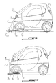
- Figure 4 is a side view showing the guidance of the electric vehicle relative to the portable housing placed on the ground.
- FIG. 5 shows the electric vehicle, the energy receiver of which is correctly placed above the inductor of the portable box placed on the ground.
- the reference 1 designates an electric vehicle on which is permanently mounted an energy receiver 2 preferably produced in the form of a flat spiral winding and which can be electromagnetically coupled to an inductor 3 preferably produced in the form of a flat spiral winding enclosed in a box 4 placed on the ground, to allow recharging of the storage batteries of the vehicle 1.
- the energy receiver 2 is at least partially housed in a dielectric box secured to the structure of the vehicle 1 and is connected to the batteries thereof by means of a rectifier circuit housed in the vehicle.
- the inductor 3 is connected to a high frequency generator housed in the housing 4 as will be seen later and to the electrical supply sector via a supply cable 5.
- the receiver 2 When the receiver 2 correctly covers the inductor 3 by being separated from each other by a relatively short distance of the order of a few centimeters, the receiver 2 is electromagnetically coupled in air to the inductor 3 of so that it intercepts the electromagnetic field emitted by the inductor 3 and the electromotive force thus induced in the receiver 2 makes it possible to establish a charging current of the accumulator batteries by means of a charge regulator (not shown ) connected between the rectifier circuit and the storage batteries.
- a charge regulator not shown
- the box 4 enclosing the inductor 3 is portable and can be optionally fixed to the ground, at the parking location of the electric vehicle 1, using a central fixing screw 6 engaging in an anti-traction anchor 7 implanted in the ground so as to secure to the ground a plate 4a constituting the bottom of the housing 4.
- the box 4 comprises means for guiding the vehicle 1 to facilitate the placement of the receiver 2 above the inductor 3.
- These guide means comprise a tilting pole 8 visible to the driver of the vehicle 1, removably attached to a switch 9 fixed to the cover 4b of the housing 4 and capable of occupying either a position for deactivation of an electronic unit 10 comprising the generator high frequency, so that no electromagnetic field is emitted by the inductor 3, or a position for commissioning the electronic unit 10 so that the inductor 3 can emit the electromagnetic field allowing recharging of storage batteries of the vehicle 1.
- the electronic unit 10 and the inductor 3 are housed in the casing 4c of the unit 4.
- the pole 8 is equipped at its upper free end with a light indicator 11, such as a light-emitting diode, which can light up when the switch 9 switches from its position for deactivation of the electronic unit 10 to its position of commissioning of it.
- a light indicator 11 such as a light-emitting diode
- the guide means may also include at least one guide light 12 fixed to the casing 4c of the housing 4 in front of the latter, in any case opposite to the switch 9, so as to be visible to the driver of the electric vehicle 1 during his approach to the housing 4.
- the power cable 5 for connecting the high frequency generator to the power sector is housed in an appropriate storage space of the housing 4 which also includes cooling means, such as fins 13 for cooling by natural convection.
- an anti-theft cover 14 is fixed in an opening of conjugate shape 15 of the cover 4b so as to prevent access to the fixing screw 6.
- the driver of the vehicle 1 installs the portable box 4 on the parking space of the vehicle and, optionally, fixes this box on the ground using the central screw 6, then then fixes the anti-theft cover 14 to the cover 4b of the housing 4.
- the conductor then connects the power cable 5 to the mains and installs the pole 8 on the switch 9 embedded in the cover 4b.
- the driver advances his vehicle slowly towards the recharging unit 4, already positioning the vehicle 1 relative to the unit 4 using the guide light 12.
- the vehicle 1 moves above the unit 4, he pushes the pole 8 so as to switch the switch 9 from its position in which it cuts off the transfer of inductive energy necessary to recharge the vehicle storage batteries in its position in which it authorizes this transfer of inductive energy recharging the storage batteries.
- the light-emitting diode for example of red color, lights up to facilitate the guiding of the vehicle.
- the high frequency generator being then started, creates the electromagnetic field emitted by the inductor 3 and intercepted by the receiver 2.
- a warning light 15 of the vehicle 1 such as for example an indicator light, comes on.
- the driver stops his vehicle and, at this instant, the pole 8 is vertical.
- the storage batteries of vehicle 1 start to recharge.
- the red diode at the end of the pole 8 goes out and the high frequency generator is put on standby.
- the pole 8 is returned to its initial position to cut the high frequency generator. If necessary, the driver can separate the box 4 from the ground and take the latter with him using the handling handle 4d as is apparent in particular from FIG. 3 in order to allow the vehicle's storage batteries to be recharged. another place.
- the device of the invention also makes it possible to recharge the vehicle's accumulator batteries which have self-discharged during a long period of non-use.
- the device of the invention can be used to heat the passenger compartment of the vehicle without using its storage batteries.
Applications Claiming Priority (2)
| Application Number | Priority Date | Filing Date | Title |
|---|---|---|---|
| FR9607639 | 1996-06-19 | ||
| FR9607639A FR2750267B1 (fr) | 1996-06-19 | 1996-06-19 | Dispositif pour recharger les batteries d'accumulateurs d'un vehicule electrique |
Publications (2)
| Publication Number | Publication Date |
|---|---|
| EP0814557A1 true EP0814557A1 (de) | 1997-12-29 |
| EP0814557B1 EP0814557B1 (de) | 2004-08-25 |
Family
ID=9493224
Family Applications (1)
| Application Number | Title | Priority Date | Filing Date |
|---|---|---|---|
| EP97401386A Expired - Lifetime EP0814557B1 (de) | 1996-06-19 | 1997-06-17 | Gerät zur Ladung der Batterien eines elektrischen Fahrzeugs |
Country Status (3)
| Country | Link |
|---|---|
| EP (1) | EP0814557B1 (de) |
| DE (1) | DE69730381D1 (de) |
| FR (1) | FR2750267B1 (de) |
Cited By (6)
| Publication number | Priority date | Publication date | Assignee | Title |
|---|---|---|---|---|
| EP0918390A2 (de) * | 1997-11-19 | 1999-05-26 | Ackermann Limited | Büroarbeitsplatzdienste |
| ES2181557A1 (es) * | 2000-11-27 | 2003-02-16 | Cisterra S L | Sistema de alimentacion de motores y recarga de baterias en vehiculos electricos. |
| WO2003022671A3 (en) * | 2001-09-13 | 2003-08-21 | Sparta B V | Cycle with auxiliary propulsion |
| US20130088194A1 (en) * | 2011-08-16 | 2013-04-11 | Nucleus Scientific, Inc. | Overhead power transfer system |
| WO2013083625A1 (de) * | 2011-12-09 | 2013-06-13 | Bayerische Motoren Werke Aktiengesellschaft | Kraftwagen |
| CN108110842A (zh) * | 2017-12-29 | 2018-06-01 | 宁夏软件工程院有限公司 | 一种自适应电能接收装置 |
Families Citing this family (3)
| Publication number | Priority date | Publication date | Assignee | Title |
|---|---|---|---|---|
| FR2962696B1 (fr) | 2010-07-16 | 2016-07-01 | Renault Sa | Charge sans contact d'une batterie de vehicule automobile. |
| EP2808976A1 (de) | 2013-05-29 | 2014-12-03 | Brusa Elektronik AG | Schaltungsanordnung für den Primärteil eines Systems zur kontaktlosen Energieübertragung, sowie Übertragerelement |
| EP3065152A1 (de) | 2015-03-06 | 2016-09-07 | Brusa Elektronik AG | Primärteil eines induktiven ladegeräts |
Citations (3)
| Publication number | Priority date | Publication date | Assignee | Title |
|---|---|---|---|---|
| US3938018A (en) * | 1974-09-16 | 1976-02-10 | Dahl Ernest A | Induction charging system |
| US4347472A (en) * | 1980-10-20 | 1982-08-31 | Lemelson Jerome H | Apparatus and method for charging a battery in a vehicle |
| EP0586315A1 (de) * | 1992-09-02 | 1994-03-09 | Cableco | Einheit zum Wiederaufladen von Akkumulatorbatterien eines elektrisch angetriebenen Kraftfahrzeugs |
-
1996
- 1996-06-19 FR FR9607639A patent/FR2750267B1/fr not_active Expired - Fee Related
-
1997
- 1997-06-17 DE DE69730381T patent/DE69730381D1/de not_active Expired - Lifetime
- 1997-06-17 EP EP97401386A patent/EP0814557B1/de not_active Expired - Lifetime
Patent Citations (3)
| Publication number | Priority date | Publication date | Assignee | Title |
|---|---|---|---|---|
| US3938018A (en) * | 1974-09-16 | 1976-02-10 | Dahl Ernest A | Induction charging system |
| US4347472A (en) * | 1980-10-20 | 1982-08-31 | Lemelson Jerome H | Apparatus and method for charging a battery in a vehicle |
| EP0586315A1 (de) * | 1992-09-02 | 1994-03-09 | Cableco | Einheit zum Wiederaufladen von Akkumulatorbatterien eines elektrisch angetriebenen Kraftfahrzeugs |
Cited By (9)
| Publication number | Priority date | Publication date | Assignee | Title |
|---|---|---|---|---|
| EP0918390A2 (de) * | 1997-11-19 | 1999-05-26 | Ackermann Limited | Büroarbeitsplatzdienste |
| EP0918390A3 (de) * | 1997-11-19 | 2000-03-22 | Ackermann Limited | Büroarbeitsplatzdienste |
| ES2181557A1 (es) * | 2000-11-27 | 2003-02-16 | Cisterra S L | Sistema de alimentacion de motores y recarga de baterias en vehiculos electricos. |
| WO2003022671A3 (en) * | 2001-09-13 | 2003-08-21 | Sparta B V | Cycle with auxiliary propulsion |
| US20130088194A1 (en) * | 2011-08-16 | 2013-04-11 | Nucleus Scientific, Inc. | Overhead power transfer system |
| WO2013083625A1 (de) * | 2011-12-09 | 2013-06-13 | Bayerische Motoren Werke Aktiengesellschaft | Kraftwagen |
| CN103958245A (zh) * | 2011-12-09 | 2014-07-30 | 宝马股份公司 | 机动车 |
| US9662992B2 (en) | 2011-12-09 | 2017-05-30 | Bayerische Motoren Werke Aktiengesellschaft | Motor vehicle having an inductive charging coil arranged on a lubricant reservoir of an internal combustion engine of the vehicle |
| CN108110842A (zh) * | 2017-12-29 | 2018-06-01 | 宁夏软件工程院有限公司 | 一种自适应电能接收装置 |
Also Published As
| Publication number | Publication date |
|---|---|
| FR2750267B1 (fr) | 1998-09-18 |
| DE69730381D1 (de) | 2004-09-30 |
| EP0814557B1 (de) | 2004-08-25 |
| FR2750267A1 (fr) | 1997-12-26 |
Similar Documents
| Publication | Publication Date | Title |
|---|---|---|
| US3963972A (en) | Portable power package | |
| EP3472919B1 (de) | Tragbare vorrichtung zur ausgabe eines stromkabels, insbesondere eines ladekabels für ein elektro- oder hybridfahrzeug | |
| CA2305228C (en) | Self-contained recharging device for portable telephone and/or battery and/or protective case | |
| EP0814557B1 (de) | Gerät zur Ladung der Batterien eines elektrischen Fahrzeugs | |
| EP0586315A1 (de) | Einheit zum Wiederaufladen von Akkumulatorbatterien eines elektrisch angetriebenen Kraftfahrzeugs | |
| FR2828787A1 (fr) | Tondeuse a gazon electrique | |
| JP2000243458A (ja) | パワーパック充電システムおよび電動工具充電システム | |
| EP0536056B1 (de) | Ladesteckdose für motorisiertes Elektrofahrzeug | |
| EP2230142A1 (de) | Interaktives Verfahren zum Wechseln eines Energie-Speichersystems in einen elektrischen oder teilweise elektrischen Fahrzeug. | |
| FR2732169A1 (fr) | Dispositif pour recharger les batteries d'accumulateurs d'un vehicule electrique | |
| FR2613674A1 (fr) | Coffret de rangement, a tiroir a lampe mobile pour automobile | |
| EP2710445B1 (de) | Schutzhülle für eine spielkonsole | |
| FR3093964A1 (fr) | Carport autonome et transportable pour recharger les véhicules électriques | |
| EP1363380A1 (de) | Generator für die Versorgung einer Batterie für tragbares Gerät insbesondere tragbares Telefon | |
| FR2992275A1 (fr) | Vehicule pourvu d'un moteur hybride | |
| EP0858172B1 (de) | Tragbares Gerät, und Batteriegehäuse des tragbaren Gerätes für Gebrauch von verschiedenen Batterietypen konstruiert | |
| EP1729392B1 (de) | Elektrisches Kraftfahrzeug-Bordnetz | |
| WO2022167350A1 (fr) | Véhicule électrique doté d'un adaptateur pour la recharge d'une batterie électrique | |
| FR2988068A1 (fr) | Systeme automatique de stockage de cycles, cycle pour un tel systeme et utilisation d'une batterie pour un tel cycle. | |
| WO2012042179A2 (fr) | Charge sans contact d'une batterie de vehicule automobile | |
| FR2549297A1 (fr) | Dispositif de securite pour un appareil electrique a accumulateur rechargeable | |
| EP0784324A1 (de) | Behälter für Platten, insbesondere für Compact Discs mit integriertem Radioempfänger, insbesondere FM | |
| EP0838378B1 (de) | Kraftfahrzeugdiebstahlsicherung mit zusammenarbeitendem Zündschloss | |
| KR100195055B1 (ko) | 점프케이블감김대를 갖는 자동차용 밧데리 | |
| WO2022200497A1 (fr) | Dispositif autonome d'alimentation électrique, notamment pour charger une batterie |
Legal Events
| Date | Code | Title | Description |
|---|---|---|---|
| PUAI | Public reference made under article 153(3) epc to a published international application that has entered the european phase |
Free format text: ORIGINAL CODE: 0009012 |
|
| AK | Designated contracting states |
Kind code of ref document: A1 Designated state(s): CH DE ES GB IT LI PT SE |
|
| 17P | Request for examination filed |
Effective date: 19980613 |
|
| AKX | Designation fees paid |
Free format text: CH DE ES GB IT LI PT SE |
|
| RBV | Designated contracting states (corrected) |
Designated state(s): CH DE ES GB IT LI PT SE |
|
| 17Q | First examination report despatched |
Effective date: 20000203 |
|
| GRAP | Despatch of communication of intention to grant a patent |
Free format text: ORIGINAL CODE: EPIDOSNIGR1 |
|
| GRAS | Grant fee paid |
Free format text: ORIGINAL CODE: EPIDOSNIGR3 |
|
| GRAA | (expected) grant |
Free format text: ORIGINAL CODE: 0009210 |
|
| AK | Designated contracting states |
Kind code of ref document: B1 Designated state(s): CH DE ES GB IT LI PT SE |
|
| PG25 | Lapsed in a contracting state [announced via postgrant information from national office to epo] |
Ref country code: IT Free format text: LAPSE BECAUSE OF FAILURE TO SUBMIT A TRANSLATION OF THE DESCRIPTION OR TO PAY THE FEE WITHIN THE PRESCRIBED TIME-LIMIT;WARNING: LAPSES OF ITALIAN PATENTS WITH EFFECTIVE DATE BEFORE 2007 MAY HAVE OCCURRED AT ANY TIME BEFORE 2007. THE CORRECT EFFECTIVE DATE MAY BE DIFFERENT FROM THE ONE RECORDED. Effective date: 20040825 Ref country code: GB Free format text: LAPSE BECAUSE OF FAILURE TO SUBMIT A TRANSLATION OF THE DESCRIPTION OR TO PAY THE FEE WITHIN THE PRESCRIBED TIME-LIMIT Effective date: 20040825 |
|
| REG | Reference to a national code |
Ref country code: GB Ref legal event code: FG4D Free format text: NOT ENGLISH |
|
| REG | Reference to a national code |
Ref country code: CH Ref legal event code: EP |
|
| REF | Corresponds to: |
Ref document number: 69730381 Country of ref document: DE Date of ref document: 20040930 Kind code of ref document: P |
|
| PG25 | Lapsed in a contracting state [announced via postgrant information from national office to epo] |
Ref country code: SE Free format text: LAPSE BECAUSE OF FAILURE TO SUBMIT A TRANSLATION OF THE DESCRIPTION OR TO PAY THE FEE WITHIN THE PRESCRIBED TIME-LIMIT Effective date: 20041125 |
|
| PG25 | Lapsed in a contracting state [announced via postgrant information from national office to epo] |
Ref country code: DE Free format text: LAPSE BECAUSE OF FAILURE TO SUBMIT A TRANSLATION OF THE DESCRIPTION OR TO PAY THE FEE WITHIN THE PRESCRIBED TIME-LIMIT Effective date: 20041126 |
|
| PG25 | Lapsed in a contracting state [announced via postgrant information from national office to epo] |
Ref country code: ES Free format text: LAPSE BECAUSE OF FAILURE TO SUBMIT A TRANSLATION OF THE DESCRIPTION OR TO PAY THE FEE WITHIN THE PRESCRIBED TIME-LIMIT Effective date: 20041206 |
|
| GBV | Gb: ep patent (uk) treated as always having been void in accordance with gb section 77(7)/1977 [no translation filed] |
Effective date: 20040825 |
|
| PG25 | Lapsed in a contracting state [announced via postgrant information from national office to epo] |
Ref country code: LI Free format text: LAPSE BECAUSE OF NON-PAYMENT OF DUE FEES Effective date: 20050630 Ref country code: CH Free format text: LAPSE BECAUSE OF NON-PAYMENT OF DUE FEES Effective date: 20050630 |
|
| PLBE | No opposition filed within time limit |
Free format text: ORIGINAL CODE: 0009261 |
|
| STAA | Information on the status of an ep patent application or granted ep patent |
Free format text: STATUS: NO OPPOSITION FILED WITHIN TIME LIMIT |
|
| 26N | No opposition filed |
Effective date: 20050526 |
|
| REG | Reference to a national code |
Ref country code: CH Ref legal event code: PL |
|
| PG25 | Lapsed in a contracting state [announced via postgrant information from national office to epo] |
Ref country code: PT Free format text: LAPSE BECAUSE OF NON-PAYMENT OF DUE FEES Effective date: 20050125 |