EP0814343B1 - Optical head of optical beacon - Google Patents
Optical head of optical beacon Download PDFInfo
- Publication number
- EP0814343B1 EP0814343B1 EP97109870A EP97109870A EP0814343B1 EP 0814343 B1 EP0814343 B1 EP 0814343B1 EP 97109870 A EP97109870 A EP 97109870A EP 97109870 A EP97109870 A EP 97109870A EP 0814343 B1 EP0814343 B1 EP 0814343B1
- Authority
- EP
- European Patent Office
- Prior art keywords
- light
- light emitting
- optical
- transmission window
- light receiving
- Prior art date
- Legal status (The legal status is an assumption and is not a legal conclusion. Google has not performed a legal analysis and makes no representation as to the accuracy of the status listed.)
- Expired - Lifetime
Links
Images
Classifications
-
- G—PHYSICS
- G08—SIGNALLING
- G08G—TRAFFIC CONTROL SYSTEMS
- G08G1/00—Traffic control systems for road vehicles
- G08G1/09—Arrangements for giving variable traffic instructions
- G08G1/0962—Arrangements for giving variable traffic instructions having an indicator mounted inside the vehicle, e.g. giving voice messages
- G08G1/0967—Systems involving transmission of highway information, e.g. weather, speed limits
- G08G1/096708—Systems involving transmission of highway information, e.g. weather, speed limits where the received information might be used to generate an automatic action on the vehicle control
- G08G1/096716—Systems involving transmission of highway information, e.g. weather, speed limits where the received information might be used to generate an automatic action on the vehicle control where the received information does not generate an automatic action on the vehicle control
-
- G—PHYSICS
- G01—MEASURING; TESTING
- G01S—RADIO DIRECTION-FINDING; RADIO NAVIGATION; DETERMINING DISTANCE OR VELOCITY BY USE OF RADIO WAVES; LOCATING OR PRESENCE-DETECTING BY USE OF THE REFLECTION OR RERADIATION OF RADIO WAVES; ANALOGOUS ARRANGEMENTS USING OTHER WAVES
- G01S1/00—Beacons or beacon systems transmitting signals having a characteristic or characteristics capable of being detected by non-directional receivers and defining directions, positions, or position lines fixed relatively to the beacon transmitters; Receivers co-operating therewith
- G01S1/70—Beacons or beacon systems transmitting signals having a characteristic or characteristics capable of being detected by non-directional receivers and defining directions, positions, or position lines fixed relatively to the beacon transmitters; Receivers co-operating therewith using electromagnetic waves other than radio waves
- G01S1/703—Details
- G01S1/7032—Transmitters
-
- G—PHYSICS
- G08—SIGNALLING
- G08G—TRAFFIC CONTROL SYSTEMS
- G08G1/00—Traffic control systems for road vehicles
- G08G1/09—Arrangements for giving variable traffic instructions
- G08G1/0962—Arrangements for giving variable traffic instructions having an indicator mounted inside the vehicle, e.g. giving voice messages
- G08G1/0967—Systems involving transmission of highway information, e.g. weather, speed limits
- G08G1/096733—Systems involving transmission of highway information, e.g. weather, speed limits where a selection of the information might take place
- G08G1/096758—Systems involving transmission of highway information, e.g. weather, speed limits where a selection of the information might take place where no selection takes place on the transmitted or the received information
-
- G—PHYSICS
- G08—SIGNALLING
- G08G—TRAFFIC CONTROL SYSTEMS
- G08G1/00—Traffic control systems for road vehicles
- G08G1/09—Arrangements for giving variable traffic instructions
- G08G1/0962—Arrangements for giving variable traffic instructions having an indicator mounted inside the vehicle, e.g. giving voice messages
- G08G1/0967—Systems involving transmission of highway information, e.g. weather, speed limits
- G08G1/096766—Systems involving transmission of highway information, e.g. weather, speed limits where the system is characterised by the origin of the information transmission
- G08G1/096783—Systems involving transmission of highway information, e.g. weather, speed limits where the system is characterised by the origin of the information transmission where the origin of the information is a roadside individual element
-
- H—ELECTRICITY
- H04—ELECTRIC COMMUNICATION TECHNIQUE
- H04B—TRANSMISSION
- H04B10/00—Transmission systems employing electromagnetic waves other than radio-waves, e.g. infrared, visible or ultraviolet light, or employing corpuscular radiation, e.g. quantum communication
- H04B10/11—Arrangements specific to free-space transmission, i.e. transmission through air or vacuum
- H04B10/114—Indoor or close-range type systems
- H04B10/1143—Bidirectional transmission
-
- G—PHYSICS
- G01—MEASURING; TESTING
- G01S—RADIO DIRECTION-FINDING; RADIO NAVIGATION; DETERMINING DISTANCE OR VELOCITY BY USE OF RADIO WAVES; LOCATING OR PRESENCE-DETECTING BY USE OF THE REFLECTION OR RERADIATION OF RADIO WAVES; ANALOGOUS ARRANGEMENTS USING OTHER WAVES
- G01S2201/00—Indexing scheme relating to beacons or beacon systems transmitting signals capable of being detected by non-directional receivers and defining directions, positions, or position lines fixed relatively to the beacon transmitters
- G01S2201/01—Indexing scheme relating to beacons or beacon systems transmitting signals capable of being detected by non-directional receivers and defining directions, positions, or position lines fixed relatively to the beacon transmitters adapted for specific applications or environments
Definitions
- the invention relates to optical beacon systems that implement communication using optical signals, and more particularly to an improved optical head structure installed within an automobile.
- An optical beacon is a type of communication system between automobiles and roads using rays of light in the near infrared region.
- the optical beacon is also a bidirectional communication system that transmits traffic information such as traffic jam and parking area information from the road side to the automobile side and that transmits IDs specific to individual automobiles and the like from the automobile side to the road side.
- beacons include radio beacons using electric waves
- optical beacons use light as their transmission medium and space propagation light as their carrier wave, and implements communication by modulating such carrier wave.
- An optical beacon uses a light emitting element and a light receiving element as elements in place of an antenna, and receives optical signals from the road side by the light receiving element and transmits optical signals from the automobile side to the road side by the light emitting element.
- the wavelength of light used is in the near infrared region around 850 nm. While a combination of the light emitting element and the light receiving element or a collective body consisting of a light emitting element and a light receiving element is called an optical beacon antenna, they will hereinafter be referred to simply as the "optical beacon".
- this optical beacon has the basic function of receiving light and emitting light. Therefore, when an optical beacon is enclosed with a body, a transmission window must be formed in the body in order to ensure transmission of light.
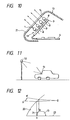
- Fig. 9 is a schematic diagram showing a body 13 of an optical beacon 10 having such a transmission window 14.
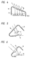
- Fig. 5 shows a conventional example of an optical head 10 of an optical beacon (hereinafter referred to simply as the "optical head 10") used for automobiles.
- this optical head 10 has a light emitting section 11 and a light receiving section 12 mounted on a single board 3.
- the light emitting section 11 has an array of light emitting elements 1 that are constructed of LEDs (light-emitting diodes), and the light receiving section 12 has a large area light receiving element 2 constructed of a PD (photodiode).
- reference numeral 13 denotes a body and 14, a transmission window for transmission and reception of light.
- this mounting board 3 is disposed so as to be inclined at an angle corresponding to an optimal directive angle of the optical head 10 with respect to the upper surface of a substantially horizontal installation surface within an automobile, e.g., the upper surface of an instrument panel so that the transmission and reception efficiency of the light emitting elements 1 and the light receiving element 2 (hereinafter referred to simply as the "optical element” collectively whenever applicable) is optimized.
- the optimal directive angle of the optical head 10 is set to, e.g., 43° ⁇ 10° with respect to a horizontal plane.
- the reason why the LEDs are arrayed is not only to increase the sum total of energy but also to make a fine adjustment of the directive angle as a whole by individually setting the mounting angles of the respective LEDs as shown in Fig. 9.
- the arrows indicate light emitting directions.
- the light emitting elements 1 and the light receiving element 2 are arranged on a single board 3 in the example shown in Fig. 9, they may not necessarily be arranged in such a manner.
- the light emitting elements 1 and the light receiving element 2 may be arranged in any mode as long as such mode allows rays of light to be transmitted and received through the transmission window 14 formed in a surface 21 of the body 13 confronting the windshield glass surface when the light emitting elements 1 and the light receiving element 2 are accommodated in the body 13 such as shown in Fig. 10.
- a road-side optical beacon unit 52 and an automobile-side optical beacon unit 51 are arranged as shown in Fig. 11, respectively, and the directive angle of the antenna of the automobile-side unit 51 is required to be set to 43° ⁇ 10° with respect to a horizontal plane. If the body 13 of the optical beacon 10 is to be arranged inside the automobile room, the optical beacon 10 can most advantageously keep this directive angle when placed on the upper surface of an instrument panel 23 that confronts a windshield glass 20 such as shown in Fig. 12. Almost all the body 13 of the optical beacons 10 are disposed on the upper surface of the instrument panel 23 that is substantially horizontal.
- light is scattered by, e.g., embossing the surface of the body 13 in order to control the reflectance of the surface of the body 13, or the surface pattern of the body 13 is made analogous to that of the instrument panel 23 in order to give continuity to the instrument panel 23, or the number of partings is reduced, etc.
- the control board 4 and the mounting board 3 must be arranged under different layout systems spacewise as shown in Figs. 9 and 10, taking into consideration ease with which to operate the control board for controlling the optical element.
- the control board 4 and the mounting board 3 are usually formed to be separate pieces.
- the arrangement in which the LEDs are arrayed with each LED being inclined at a certain angle addresses a serious problem that the number of manufacturing steps is increased and that management is complicated. Further, if the LEDs must be rearrayed for adjustment of their directive angles after mounted, the LEDs may likely be mechanically deformed due to vibrations or the like during the operation or may likely break connecting electric wires.
- Document EP 0 322 573 A1 discloses an optical beacon, which body is mounted on an instrument panel of an automobile. Further, the body of the optical beacon is coated in black and is inclined backwardly, so as to prevent the transmission window or the transparent transmission surface, respectively, to be mirrored in the windshield.
- a mechanical mechanism included in the body of the optical beacon is used for optimally adjusting the transmission direction of the light emitting means and the light receiving means.
- a converging lens is used for refracting the transmitted light.
- An first object of the invention is therefore to prevent the mirroring of reflected images of the body of an optical beacon and the transmission window of the body on the windshield glass without losing the transmitting function of the transmission window of the body, the body being disposed so as to face the windshield glass and the transmission window serving to allow the optical beacon inside the body to implement transmission and reception of optical signals.
- a second object of the invention is to overcome these problems and to allow a highly reliable and inexpensive optical head whose directivity is easily adjustable to be manufactured.
- the invention provides an optical head having the features of claim 1. As a result of this arrangement, at least the surface of the transmission window is not mirrored on the windshield glass.
- a surface treatment for preventing the mirroring of an image on the windshield glass surface may be given to a surface portion of the body excluding the transmission window.
- refracting means may be arranged on an inner surface of the transmission window or between the inner surface of the transmission window and the light emitting element and the light receiving element, so that light transmitting and receiving directions can be adjusted, the refracting means serving to change travelling paths of rays of light.
- a prism may be used as the refracting means.
- the directions of rays of light emitted from the transmission window of the body can be set arbitrarily. Therefore, light transmission and reception efficiency can be optimized by aligning the directions of transmission of light from the light emitting elements and the direction of reception of light to the light receiving element with the optical axes of these elements (i.e., aligning the directions to be in parallel with the optical axes) independently of where the transmission window is positioned or into which shape the transmission window is formed.
- the invention is characterized in that an optical path of an optical signal emitted from a light emitting element is operated by refracting means so that a desired radiation pattern can be formed.
- a ray of light from the optical head can be injected in an arbitrary direction independently of how the light emitting element is arranged.
- the invention is characterized in that, in an optical head having a plurality of light emitting elements, the refracting means are arranged so as to correspond to the respective light emitting elements so that a desired radiation pattern can be formed as a whole.
- a prism can be used as the refracting means.
- the invention is characterized in that the refracting means is arranged ahead of the light receiving element so that the refracting means can curve an optical path of the optical signal that is emitted from the light emitting element and that is to be received by the light receiving element in such a manner that the optical signal is converged onto the light receiving element.
- a converging lens can be used as the refracting means.
- the light injected onto the optical head can be converged immediately ahead of the light receiving element, the light receiving area can be reduced compared with an example having no such configuration while keeping the same effective light receiving area.
- the refracting means that is arranged in the configurations may be formed by using a transparent body and being integrated with a transmission window, the transparent body forming the transmission window that is arranged in a body of the optical head and that serves for transmission and reception.
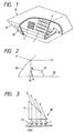
- Fig. 1 shows a body 13 of an optical beacon 10, which is a first embodiment.
- Fig. 2 is a schematic diagram showing the arrangement of the body 1 on the upper surface of an instrument panel 23 so as to face a windshield glass 20.
- a surface 21 in which a transmission window 14 of the body 1 serving for transmission and reception is formed is positioned so as to confront a surface of the windshield glass 20.
- the surface 21 in which the transmission window 1 is formed is inclined backward with respect to the automobile travelling direction from an upper edge a to a lower edge b as shown in Fig. 2.
- an image of the surface 21 of the body 1 in which the transmission window 14 is formed is not mirrored on the windshield glass 20, the image being that of a portion below the upper edge a excluding the upper edge a as indicated by the optical path in Fig. 2 (a reflected image a' of the upper edge a is mirrored). Therefore, a surface treatment for preventing the mirroring of an image on the windshield glass 20 is not required to be given to the surface 21 in which the transmission window 14 is arranged. Therefore, the function of the transmission window 14 for light can be maintained.
- the surface treatment for preventing the mirroring of an image can be given to surfaces other than the surface 21 in which the transmission window 14 is formed. Therefore, if the surface treatment for preventing the mirroring of an image is provided not only on the surfaces other than the surface 21 in which the transmission window 14 is formed but also on the upper edge a of the surface 21 in which the transmission window 14 is formed and if the anti-mirroring configuration (shape) including the aforementioned shape of the surface 21 in which the transmission window 14 is formed is also employed, an image of the body 13 is in no way mirrored on the windshield glass 20.
- a prism 5 is disposed immediately after light emitting elements 1 of an optical head 10 in light radiating directions of the light emitting elements 1, so that the paths along which light rays travel immediately after the radiation are curved by the prism 5.
- the light emitting elements 1 can be arranged in arbitrary positions.
- a mounting board 3 on which the light emitting elements 1 are mounted has no longer be inclined in order to form an optimal radiation pattern.
- the mounting board 3 can be located within the same plane as a control board 4. If there is an open space on the control board 4, the light emitting elements 1 can be mounted on the control board 4, which in turn allows the mounting board 3 to be integrated with the control board 4. As a result of this configuration, the problem discussed in the prior art can be overcome. It may be noted that LEDs are used as the light emitting elements 1.
- a plurality of prisms 5 are disposed so as to correspond to the respective light emitting elements 1 and the shapes and mounting directions of these prisms 5 are changed as shown in Fig. 4, so that the directivity as a whole can be adjusted without rearranging the light emitting elements 1.
- the surface of a transparent body, which forms a transmission window 14 in a body of the optical head 10 for transmission and reception e.g., a transparent resin plate, a glass plate, or the like, is made into a prismatic shape, the aforementioned function can be implemented without increasing the number of parts.
- a converging lens 6 is arranged ahead of the light receiving element 2 so that light rays injected onto the optical head 10 is converged to reach the light receiving element 2 as shown in Fig. 5.
- This configuration allows the area of the light receiving element 2 itself to be reduced while keeping the same effective light receiving area as in the case where no such configuration is made. Therefore, advantages such as improved speed of response and reduced noise can be obtained. Further, since the light receiving element 2 used is small-sized, the material cost becomes low. Hence, this configuration allows the problem discussed in the prior art to be overcome.
- Fig. 6 shows a configuration in which the surface of the transmission window 14 is made to be lenslike, instead of arranging the converging lens 6 with respect to the light receiving element 2.
- the surface of the transmission window 14 can play the role as the converging lens 6. Since the converging lens 6 itself is dispensed with in this configuration, the number of parts can be reduced, and the number of manufacturing steps can be reduced as well.
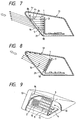
- a prism 5 is arranged close to the inner surface of the transmission window 1 as shown in Fig. 7, in addition to the shape of the body 13 according to the first mode of embodiment, so that rays of light emitted from light emitting elements 1 or a ray of light heading toward a light receiving element 2 within the body 13 from a transmitter outside the automobile pass through this prism 5 and the travelling paths thereof are curved.
- the optical paths can be curved in obliquely upward, optimal transmitting and receiving directions, e.g., in the case shown in Fig. 7.
- the prism 5 is not arranged, the surface 21 in which the transmission window 14 is formed is inclined, so that the travelling of rays of light in the optimal transmitting and receiving directions indicated by the thick arrows in Fig. 8 from the light emitting elements 1 and to the light receiving element 2 are shielded.
- the optical paths can be curved in the optimal transmitting and receiving directions, thereby allowing transmission and reception efficiency to be optimized independently of the inclination of the transmission window 21 or the surface 21 in which the transmission window 21 is formed.
- prisms 5 whose angles of slopes and indices of refraction are different may be used.
- the prism 5 is arranged so as to be secured to the inner surface of the transmission window 14 in this embodiment, the prism 5 may be arranged in other modes as well.
- the prism 5 may be arranged in a space between an optical antenna and the transmission window 14.
- the prism 5 may be arranged in any mode as long as such mode allows the travelling paths of light to be curved.
- the body of an optical beacon is formed in such a manner that either a surface thereof in which a transmission window for transmission and reception is formed or a surface extending at least from the upper edge to the lower edge of the region in which the transmission window is formed is inclined backward with respect to the travelling direction of the automobile. Therefore, even if such a body is installed on the instrument panel, the transmission window or the surface in which the transmission window is formed is not mirrored on the windshield glass, and other part of the body may be subjected to a surface treatment for preventing the mirroring of a reflected image. As a result, by providing such a surface treatment and by adopting the aforementioned transmission window design, the mirroring of a reflected image on the windshield glass can be prevented. Hence, the driver's view is in no way disturbed by the reflected image.
- refracting means is disposed immediately after the light emitting elements of an optical head in light radiating directions of the light emitting elements, and directivity is adjusted by operating the optical paths through the refracting means. Therefore, the light emitting elements can be mounted at arbitrary positions, and the light emitting elements can be mounted on an open space on a control board without providing a mounting board dedicated to the light emitting elements. Hence, a compact configuration can be achieved. In addition, unlike in the conventional example in which directivity is adjusted on the side of the light emitting elements, there are no losses or the like of the light emitting elements during adjustment, which in turn contributes to providing a highly reliable, easy-to-adjust optical head.
- the light receiving element On the side of the light receiving element also, light rays injected onto the light receiving element are converged by arranging refracting and converging means ahead of the light receiving element. Therefore, unlike in the conventional example in which there is no such means, the area of the light receiving element itself is reduced in order to obtain the same effective light receiving area. As a result, speed of response can be improved, and shot noise can be suppressed.
- the light receiving element can be inexpensive as well.
Landscapes
- Physics & Mathematics (AREA)
- General Physics & Mathematics (AREA)
- Life Sciences & Earth Sciences (AREA)
- Atmospheric Sciences (AREA)
- Engineering & Computer Science (AREA)
- Electromagnetism (AREA)
- Computer Networks & Wireless Communication (AREA)
- Radar, Positioning & Navigation (AREA)
- Remote Sensing (AREA)
- Signal Processing (AREA)
- Optical Communication System (AREA)
- Optical Elements Other Than Lenses (AREA)
Description
Claims (5)
- An optical head (10) of an optical beacon comprising:wherein a surface (21) of the body (13) in which the transmission window (14) is formed, or at least a region in which the transmission window (14) is formed is designed so as to be inclined backward with respect to a travelling direction of the automobile, the inclined surface (21) or region extending from an upper edge to a lower edge thereof; andlight emitting means (1) for transmitting an optical signal;light receiving means (2) for receiving an optical signal;a body (13) for accommodating said light emitting means (1) and said light receiving means (2), said body (13) having a transmission window (14) formed so as to confront a windshield glass surface (21) of an automobile, the transmission window (14) allowing the light emitting means (1) and the light receiving means (2) to effect transmission and reception to and from an external source,
light refracting means for changing an optical path of the optical signal emitted from the light emitting means (1) so that a desired radiation pattern can be formed,
characterized in that a prism (5) is used as said refracting means for changing a travelling path of the light to adjust light transmitting and receiving directions. - The optical head as claimed in claim 1, wherein a surface treatment for preventing the mirroring of an image on the windshield glass surface (21) is given to a surface portion of the body (13) excluding the transmission window (14).
- The optical head as claimed in claim 1 or 2, wherein said refracting means being arranged on an inner surface (21) of the transmission window (14) or between the inner surface of the transmission window (14) and the light emitting means (1) and the light receiving means (2).
- The optical head as claimed in any one of claims 1 to 3, wherein the optical head (10) has a plurality of light emitting means (1), and the refracting means are arranged so as to correspond to the respective light emitting means (1) so that a desired radiation pattern can be formed as a whole.
- The optical head as claimed in any one of claims 1 to 4, wherein the refracting means is arranged ahead of the light receiving means (2) so that the refracting means can curve an optical path of the optical signal that is emitted from the light emitting means (1) and that is to be received by the light receiving means (2) in such a manner that the optical signal is converged onto the light receiving means (2).
Applications Claiming Priority (6)
| Application Number | Priority Date | Filing Date | Title |
|---|---|---|---|
| JP155679/96 | 1996-06-17 | ||
| JP8155679A JPH10995A (en) | 1996-06-17 | 1996-06-17 | Automotive optical beacon antenna housing |
| JP155290/96 | 1996-06-17 | ||
| JP15529096 | 1996-06-17 | ||
| JP15529096 | 1996-06-17 | ||
| JP15567996 | 1996-06-17 |
Publications (3)
| Publication Number | Publication Date |
|---|---|
| EP0814343A2 EP0814343A2 (en) | 1997-12-29 |
| EP0814343A3 EP0814343A3 (en) | 1998-08-05 |
| EP0814343B1 true EP0814343B1 (en) | 2004-03-17 |
Family
ID=26483329
Family Applications (1)
| Application Number | Title | Priority Date | Filing Date |
|---|---|---|---|
| EP97109870A Expired - Lifetime EP0814343B1 (en) | 1996-06-17 | 1997-06-17 | Optical head of optical beacon |
Country Status (3)
| Country | Link |
|---|---|
| US (1) | US5999296A (en) |
| EP (1) | EP0814343B1 (en) |
| DE (1) | DE69728084D1 (en) |
Families Citing this family (4)
| Publication number | Priority date | Publication date | Assignee | Title |
|---|---|---|---|---|
| US8144056B2 (en) * | 2009-01-16 | 2012-03-27 | Rf Code, Inc. | Directional beacon device |
| AT512638B1 (en) * | 2012-06-29 | 2013-10-15 | Ferdinand Maier | Infrared remote control |
| JP2022511780A (en) * | 2018-11-28 | 2022-02-01 | シャークニンジャ オペレーティング エルエルシー | Optical Beacon for Autonomous Devices and Autonomous Devices configured to Use Optical Beacons |
| CN112858228B (en) * | 2021-01-22 | 2023-04-28 | 西安应用光学研究所 | Device and method for measuring transmission resolution of large-size optical window part |
Family Cites Families (8)
| Publication number | Priority date | Publication date | Assignee | Title |
|---|---|---|---|---|
| US4325146A (en) * | 1979-12-20 | 1982-04-13 | Lennington John W | Non-synchronous object identification system |
| EP0235678A1 (en) * | 1986-02-21 | 1987-09-09 | Siemens Aktiengesellschaft | Transmitting and receiving device to be fitted in a vehicle |
| EP0312010A3 (en) * | 1987-10-15 | 1989-08-02 | Siemens Aktiengesellschaft | Transmitter and receiver device for the transmission of information by light beams |
| EP0322573A1 (en) * | 1987-12-01 | 1989-07-05 | Siemens Aktiengesellschaft | Vehicle terminal |
| US5416627A (en) * | 1988-09-06 | 1995-05-16 | Wilmoth; Thomas E. | Method and apparatus for two way infrared communication |
| JP2899013B2 (en) * | 1989-07-03 | 1999-06-02 | 俊弘 津村 | Position information transmission system for moving objects |
| US5073979A (en) * | 1990-05-29 | 1991-12-17 | Webb Edward L | Reflector for infrared remote control transmitter |
| JP2696730B2 (en) * | 1991-07-15 | 1998-01-14 | 潤一 西澤 | Light emitting device for identification |
-
1997
- 1997-05-28 US US08/864,623 patent/US5999296A/en not_active Expired - Fee Related
- 1997-06-17 DE DE69728084T patent/DE69728084D1/en not_active Expired - Lifetime
- 1997-06-17 EP EP97109870A patent/EP0814343B1/en not_active Expired - Lifetime
Also Published As
| Publication number | Publication date |
|---|---|
| US5999296A (en) | 1999-12-07 |
| EP0814343A2 (en) | 1997-12-29 |
| DE69728084D1 (en) | 2004-04-22 |
| EP0814343A3 (en) | 1998-08-05 |
Similar Documents
| Publication | Publication Date | Title |
|---|---|---|
| US8471513B2 (en) | Rain sensor | |
| EP1416292B1 (en) | Optical scanning radar system | |
| US20060012990A1 (en) | Optics for controlling the direction of light rays and assemblies incorporating the optics | |
| US7893865B2 (en) | Vehicular lamp | |
| US6685342B2 (en) | Prism structure for flash illumination devices | |
| MXPA98000644A (en) | Compact humidity sensor with collector lenses and prismat coupler | |
| CN110174678B (en) | Object detection device | |
| KR20210072081A (en) | Automotive radar and light emitting assemblies and methods and methods of use for emitting light and radar radiation | |
| US20250004139A1 (en) | Multispectral emission device for vehicles for emitting visible light, lidar and radar radiation, and method and use thereof | |
| WO1993006505A1 (en) | Optical radar | |
| US5999296A (en) | Optical head of optical beacon | |
| US5774247A (en) | Optical signal transceiver for use with diffusely transmitted optical radiation | |
| US5357099A (en) | Contact type image sensor having original support member with a reflecting surface | |
| US6455866B1 (en) | Sensor device for detecting moisture on a window | |
| US7200335B2 (en) | Optical transceiver | |
| US20100102212A1 (en) | Light detecting device | |
| US7059522B2 (en) | Object detecting apparatus having hydrophilic light radiating window | |
| KR20200033373A (en) | A lidar having a structure in which a light emitting axis and a light receiving axis coincide | |
| JPH11326498A (en) | Optical radar device for vehicles | |
| US20060278815A1 (en) | Regressive reflection type photoelectric switch | |
| WO2021039050A1 (en) | Radar device | |
| EP1533774A1 (en) | Signal lamp | |
| JPH1070512A (en) | Optical head of in-vehicle optical beacon | |
| JPH10995A (en) | Automotive optical beacon antenna housing | |
| WO2024209785A1 (en) | Radio wave sensor |
Legal Events
| Date | Code | Title | Description |
|---|---|---|---|
| PUAI | Public reference made under article 153(3) epc to a published international application that has entered the european phase |
Free format text: ORIGINAL CODE: 0009012 |
|
| 17P | Request for examination filed |
Effective date: 19970710 |
|
| AK | Designated contracting states |
Kind code of ref document: A2 Designated state(s): DE FR GB |
|
| PUAL | Search report despatched |
Free format text: ORIGINAL CODE: 0009013 |
|
| AK | Designated contracting states |
Kind code of ref document: A3 Designated state(s): AT BE CH DE DK ES FI FR GB GR IE IT LI LU MC NL PT SE |
|
| AKX | Designation fees paid | ||
| RBV | Designated contracting states (corrected) | ||
| RBV | Designated contracting states (corrected) |
Designated state(s): DE FR GB |
|
| DBV | Designated contracting states (deleted) | ||
| RBV | Designated contracting states (corrected) |
Designated state(s): DE FR GB |
|
| 17Q | First examination report despatched |
Effective date: 20020718 |
|
| RAP1 | Party data changed (applicant data changed or rights of an application transferred) |
Owner name: SUMITOMO ELECTRIC INDUSTRIES, LTD. Owner name: SUMITOMO WIRING SYSTEMS, LTD. Owner name: AUTONETWORKS TECHNOLOGIES, LTD. |
|
| GRAP | Despatch of communication of intention to grant a patent |
Free format text: ORIGINAL CODE: EPIDOSNIGR1 |
|
| GRAS | Grant fee paid |
Free format text: ORIGINAL CODE: EPIDOSNIGR3 |
|
| GRAA | (expected) grant |
Free format text: ORIGINAL CODE: 0009210 |
|
| AK | Designated contracting states |
Kind code of ref document: B1 Designated state(s): DE FR GB |
|
| PG25 | Lapsed in a contracting state [announced via postgrant information from national office to epo] |
Ref country code: FR Free format text: LAPSE BECAUSE OF FAILURE TO SUBMIT A TRANSLATION OF THE DESCRIPTION OR TO PAY THE FEE WITHIN THE PRESCRIBED TIME-LIMIT Effective date: 20040317 |
|
| REG | Reference to a national code |
Ref country code: GB Ref legal event code: FG4D |
|
| REF | Corresponds to: |
Ref document number: 69728084 Country of ref document: DE Date of ref document: 20040422 Kind code of ref document: P |
|
| PG25 | Lapsed in a contracting state [announced via postgrant information from national office to epo] |
Ref country code: GB Free format text: LAPSE BECAUSE OF NON-PAYMENT OF DUE FEES Effective date: 20040617 |
|
| PG25 | Lapsed in a contracting state [announced via postgrant information from national office to epo] |
Ref country code: DE Free format text: LAPSE BECAUSE OF FAILURE TO SUBMIT A TRANSLATION OF THE DESCRIPTION OR TO PAY THE FEE WITHIN THE PRESCRIBED TIME-LIMIT Effective date: 20040618 |
|
| PLBE | No opposition filed within time limit |
Free format text: ORIGINAL CODE: 0009261 |
|
| STAA | Information on the status of an ep patent application or granted ep patent |
Free format text: STATUS: NO OPPOSITION FILED WITHIN TIME LIMIT |
|
| GBPC | Gb: european patent ceased through non-payment of renewal fee |
Effective date: 20040617 |
|
| EN | Fr: translation not filed | ||
| 26N | No opposition filed |
Effective date: 20041220 |