EP0813937A2 - Apparatus and method for cutting food products - Google Patents
Apparatus and method for cutting food products Download PDFInfo
- Publication number
- EP0813937A2 EP0813937A2 EP97109770A EP97109770A EP0813937A2 EP 0813937 A2 EP0813937 A2 EP 0813937A2 EP 97109770 A EP97109770 A EP 97109770A EP 97109770 A EP97109770 A EP 97109770A EP 0813937 A2 EP0813937 A2 EP 0813937A2
- Authority
- EP
- European Patent Office
- Prior art keywords
- cutting element
- product
- cut
- cutting
- ultrasound
- Prior art date
- Legal status (The legal status is an assumption and is not a legal conclusion. Google has not performed a legal analysis and makes no representation as to the accuracy of the status listed.)
- Granted
Links
- 238000005520 cutting process Methods 0.000 title claims abstract description 72
- 235000013305 food Nutrition 0.000 title claims abstract description 18
- 238000000034 method Methods 0.000 title claims description 8
- 230000007246 mechanism Effects 0.000 claims abstract description 20
- 238000002604 ultrasonography Methods 0.000 claims abstract description 20
- 230000003213 activating effect Effects 0.000 claims 1
- 230000033001 locomotion Effects 0.000 description 8
- 241000196324 Embryophyta Species 0.000 description 4
- 230000000694 effects Effects 0.000 description 4
- 239000000126 substance Substances 0.000 description 4
- 235000019219 chocolate Nutrition 0.000 description 3
- 230000009286 beneficial effect Effects 0.000 description 2
- 230000000295 complement effect Effects 0.000 description 2
- 238000011161 development Methods 0.000 description 2
- 230000018109 developmental process Effects 0.000 description 2
- 239000012634 fragment Substances 0.000 description 2
- 238000004519 manufacturing process Methods 0.000 description 2
- 239000000463 material Substances 0.000 description 2
- MIDXCONKKJTLDX-UHFFFAOYSA-N 3,5-dimethylcyclopentane-1,2-dione Chemical compound CC1CC(C)C(=O)C1=O MIDXCONKKJTLDX-UHFFFAOYSA-N 0.000 description 1
- 235000013162 Cocos nucifera Nutrition 0.000 description 1
- 244000060011 Cocos nucifera Species 0.000 description 1
- 241000723382 Corylus Species 0.000 description 1
- 235000007466 Corylus avellana Nutrition 0.000 description 1
- LFQSCWFLJHTTHZ-UHFFFAOYSA-N Ethanol Chemical compound CCO LFQSCWFLJHTTHZ-UHFFFAOYSA-N 0.000 description 1
- 206010041662 Splinter Diseases 0.000 description 1
- 239000000853 adhesive Substances 0.000 description 1
- 230000001070 adhesive effect Effects 0.000 description 1
- 235000008429 bread Nutrition 0.000 description 1
- 235000013736 caramel Nutrition 0.000 description 1
- 239000011248 coating agent Substances 0.000 description 1
- 238000000576 coating method Methods 0.000 description 1
- 235000009508 confectionery Nutrition 0.000 description 1
- 239000006071 cream Substances 0.000 description 1
- 239000008187 granular material Substances 0.000 description 1
- 239000002245 particle Substances 0.000 description 1
- 235000014594 pastries Nutrition 0.000 description 1
- 230000000644 propagated effect Effects 0.000 description 1
- 239000002689 soil Substances 0.000 description 1
- 239000007787 solid Substances 0.000 description 1
- 238000003892 spreading Methods 0.000 description 1
- 230000002195 synergetic effect Effects 0.000 description 1
- 239000006188 syrup Substances 0.000 description 1
- 235000020357 syrup Nutrition 0.000 description 1
- 238000003466 welding Methods 0.000 description 1
Images

Classifications
-
- B—PERFORMING OPERATIONS; TRANSPORTING
- B26—HAND CUTTING TOOLS; CUTTING; SEVERING
- B26D—CUTTING; DETAILS COMMON TO MACHINES FOR PERFORATING, PUNCHING, CUTTING-OUT, STAMPING-OUT OR SEVERING
- B26D5/00—Arrangements for operating and controlling machines or devices for cutting, cutting-out, stamping-out, punching, perforating, or severing by means other than cutting
- B26D5/08—Means for actuating the cutting member to effect the cut
- B26D5/086—Electric, magnetic, piezoelectric, electro-magnetic means
-
- A—HUMAN NECESSITIES
- A21—BAKING; EDIBLE DOUGHS
- A21C—MACHINES OR EQUIPMENT FOR MAKING OR PROCESSING DOUGHS; HANDLING BAKED ARTICLES MADE FROM DOUGH
- A21C11/00—Other machines for forming the dough into its final shape before cooking or baking
- A21C11/10—Other machines for forming the dough into its final shape before cooking or baking combined with cutting apparatus
-
- A—HUMAN NECESSITIES
- A21—BAKING; EDIBLE DOUGHS
- A21C—MACHINES OR EQUIPMENT FOR MAKING OR PROCESSING DOUGHS; HANDLING BAKED ARTICLES MADE FROM DOUGH
- A21C15/00—Apparatus for handling baked articles
- A21C15/04—Cutting or slicing machines or devices specially adapted for baked articles other than bread
-
- B—PERFORMING OPERATIONS; TRANSPORTING
- B26—HAND CUTTING TOOLS; CUTTING; SEVERING
- B26D—CUTTING; DETAILS COMMON TO MACHINES FOR PERFORATING, PUNCHING, CUTTING-OUT, STAMPING-OUT OR SEVERING
- B26D5/00—Arrangements for operating and controlling machines or devices for cutting, cutting-out, stamping-out, punching, perforating, or severing by means other than cutting
- B26D5/08—Means for actuating the cutting member to effect the cut
- B26D5/14—Crank and pin means
-
- B—PERFORMING OPERATIONS; TRANSPORTING
- B26—HAND CUTTING TOOLS; CUTTING; SEVERING
- B26D—CUTTING; DETAILS COMMON TO MACHINES FOR PERFORATING, PUNCHING, CUTTING-OUT, STAMPING-OUT OR SEVERING
- B26D7/00—Details of apparatus for cutting, cutting-out, stamping-out, punching, perforating, or severing by means other than cutting
- B26D7/08—Means for treating work or cutting member to facilitate cutting
- B26D7/086—Means for treating work or cutting member to facilitate cutting by vibrating, e.g. ultrasonically
-
- B—PERFORMING OPERATIONS; TRANSPORTING
- B26—HAND CUTTING TOOLS; CUTTING; SEVERING
- B26D—CUTTING; DETAILS COMMON TO MACHINES FOR PERFORATING, PUNCHING, CUTTING-OUT, STAMPING-OUT OR SEVERING
- B26D7/00—Details of apparatus for cutting, cutting-out, stamping-out, punching, perforating, or severing by means other than cutting
- B26D7/26—Means for mounting or adjusting the cutting member; Means for adjusting the stroke of the cutting member
-
- B—PERFORMING OPERATIONS; TRANSPORTING
- B26—HAND CUTTING TOOLS; CUTTING; SEVERING
- B26D—CUTTING; DETAILS COMMON TO MACHINES FOR PERFORATING, PUNCHING, CUTTING-OUT, STAMPING-OUT OR SEVERING
- B26D5/00—Arrangements for operating and controlling machines or devices for cutting, cutting-out, stamping-out, punching, perforating, or severing by means other than cutting
- B26D5/08—Means for actuating the cutting member to effect the cut
- B26D5/12—Fluid-pressure means
-
- Y—GENERAL TAGGING OF NEW TECHNOLOGICAL DEVELOPMENTS; GENERAL TAGGING OF CROSS-SECTIONAL TECHNOLOGIES SPANNING OVER SEVERAL SECTIONS OF THE IPC; TECHNICAL SUBJECTS COVERED BY FORMER USPC CROSS-REFERENCE ART COLLECTIONS [XRACs] AND DIGESTS
- Y10—TECHNICAL SUBJECTS COVERED BY FORMER USPC
- Y10S—TECHNICAL SUBJECTS COVERED BY FORMER USPC CROSS-REFERENCE ART COLLECTIONS [XRACs] AND DIGESTS
- Y10S83/00—Cutting
- Y10S83/956—Ultrasonic
-
- Y—GENERAL TAGGING OF NEW TECHNOLOGICAL DEVELOPMENTS; GENERAL TAGGING OF CROSS-SECTIONAL TECHNOLOGIES SPANNING OVER SEVERAL SECTIONS OF THE IPC; TECHNICAL SUBJECTS COVERED BY FORMER USPC CROSS-REFERENCE ART COLLECTIONS [XRACs] AND DIGESTS
- Y10—TECHNICAL SUBJECTS COVERED BY FORMER USPC
- Y10T—TECHNICAL SUBJECTS COVERED BY FORMER US CLASSIFICATION
- Y10T83/00—Cutting
- Y10T83/04—Processes
- Y10T83/05—With reorientation of tool between cuts
-
- Y—GENERAL TAGGING OF NEW TECHNOLOGICAL DEVELOPMENTS; GENERAL TAGGING OF CROSS-SECTIONAL TECHNOLOGIES SPANNING OVER SEVERAL SECTIONS OF THE IPC; TECHNICAL SUBJECTS COVERED BY FORMER USPC CROSS-REFERENCE ART COLLECTIONS [XRACs] AND DIGESTS
- Y10—TECHNICAL SUBJECTS COVERED BY FORMER USPC
- Y10T—TECHNICAL SUBJECTS COVERED BY FORMER US CLASSIFICATION
- Y10T83/00—Cutting
- Y10T83/162—With control means responsive to replaceable or selectable information program
- Y10T83/173—Arithmetically determined program
- Y10T83/175—With condition sensor
- Y10T83/178—Responsive to work
-
- Y—GENERAL TAGGING OF NEW TECHNOLOGICAL DEVELOPMENTS; GENERAL TAGGING OF CROSS-SECTIONAL TECHNOLOGIES SPANNING OVER SEVERAL SECTIONS OF THE IPC; TECHNICAL SUBJECTS COVERED BY FORMER USPC CROSS-REFERENCE ART COLLECTIONS [XRACs] AND DIGESTS
- Y10—TECHNICAL SUBJECTS COVERED BY FORMER USPC
- Y10T—TECHNICAL SUBJECTS COVERED BY FORMER US CLASSIFICATION
- Y10T83/00—Cutting
- Y10T83/485—Cutter with timed stroke relative to moving work
- Y10T83/494—Uniform periodic tool actuation
- Y10T83/50—Reciprocating tool
-
- Y—GENERAL TAGGING OF NEW TECHNOLOGICAL DEVELOPMENTS; GENERAL TAGGING OF CROSS-SECTIONAL TECHNOLOGIES SPANNING OVER SEVERAL SECTIONS OF THE IPC; TECHNICAL SUBJECTS COVERED BY FORMER USPC CROSS-REFERENCE ART COLLECTIONS [XRACs] AND DIGESTS
- Y10—TECHNICAL SUBJECTS COVERED BY FORMER USPC
- Y10T—TECHNICAL SUBJECTS COVERED BY FORMER US CLASSIFICATION
- Y10T83/00—Cutting
- Y10T83/525—Operation controlled by detector means responsive to work
-
- Y—GENERAL TAGGING OF NEW TECHNOLOGICAL DEVELOPMENTS; GENERAL TAGGING OF CROSS-SECTIONAL TECHNOLOGIES SPANNING OVER SEVERAL SECTIONS OF THE IPC; TECHNICAL SUBJECTS COVERED BY FORMER USPC CROSS-REFERENCE ART COLLECTIONS [XRACs] AND DIGESTS
- Y10—TECHNICAL SUBJECTS COVERED BY FORMER USPC
- Y10T—TECHNICAL SUBJECTS COVERED BY FORMER US CLASSIFICATION
- Y10T83/00—Cutting
- Y10T83/687—By tool reciprocable along elongated edge
- Y10T83/6905—With tool in-feed
- Y10T83/691—And auxiliary means for promoting or retarding tool in-feed
- Y10T83/692—And means to vary tool in-feed speed
Definitions
- the present invention relates to apparatus for cutting food products according to the preamble to Claim 1.
- Apparatus of this type is known, for example, from EP-A-0 614 733.
- This prior art document describes the presence of a pair of cutting devices (ultrasound blades) driven by a rod and crank mechanism on a member which can travel in synchronism with, and so as to follow food products which advance on a conveyor.
- This solution constitutes an example of the many conventional solutions used for cutting food products in industrial plants for the manufacture of such products.
- the operating criteria and types of such apparatus are in fact extremely varied.
- the object of the invention is to provide an apparatus which is able to satisfy all the requirements explained above in an excellent manner.
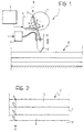
- Cutting apparatus according to the invention, generally indicated 1 in Figure 1, comprises essentially the following elements:
- this latter mechanism includes a rotary motor 6, for example an electric motor, which rotates a wheel 7 which carries a crank pin 8 at its periphery.
- a connecting rod 9 is connected to the pin 8 while its opposite end acts on the blade 2 to reciprocate it along guide elements (indicated schematically at 10) arranged perpendicular to the plane P.
- This drive mechanism is substantially the same as the crank and connecting rod drive mechanism described in EP-A-0 614 733 to which reference may usefully be made for further constructional details.
- the element 2 will move with a harmonic motion relative to the plane P, that is, with a minimum velocity (in practice nil) at the end points, the so-called upper and lower dead points of its travel relative to the plane P, reaching maximum velocity at the median point of its travel. This is true in both directions of movement and, in particular, during its advancing movement, corresponding to its cutting action. It will readily be understood that, in this case, although the velocity of advance of the element 2 varies locally, there is no possibility of varying this velocity selectively as the law governing the change of velocity with time (harmonic motion) is fixed.
- the invention is based on a recognition of the fact that the basic requirements called for in the introduction to the specification may be satisfied almost ideally if recourse is made to the use, in combination, of an ultrasound cutting apparatus and a drive mechanism for the cutting element which is able to vary the speed of advance of the cutting element through the product A being cut selectively and locally (virtually point by point, whenever requirements necessitate it and, in any case, according to any law whatsoever, selected according to the applicational requirements).
- Figure 2 shows a portion of a food product A including two layers of sponge S (possibly moistened with a sugar- or alcohol-based syrup) between which is a layer C of a creamy filling or paste constituted, for example, by a milk-flavoured cream.
- sponge S possibly moistened with a sugar- or alcohol-based syrup
- a layer C of a creamy filling or paste constituted, for example, by a milk-flavoured cream.
- the product A illustrated in Figure 4 comprises an intermediate layer K of chocolate, mou (caramel) or like substance which is, on the whole, rather solid, interposed between two sponge layers S.
- Figures 2 and 4 have been chosen appositely to illustrate two complementary situations.
- the cutting systems most frequently used in the food sector, particularly in the confectionery sector, make use of mechanically-driven cutting elements, the automatic operation of which is designed to reproduce the cutting action that a baker or pastry chef can achieve with a kitchen knife or similar tool such as a bread knife.
- a certain distance should be understood, with reference to usual thicknesses of food products such as confectionary items subjected to cutting (typical thicknesses are from 1 to 3 cm approximately), as relating to magnitudes of the order of a millimetre/several millimetres.
- the cutting element 2 is an ultrasound element has been found to be beneficial in that, with every probability of a microscopic shaking effect, the effects of adhesion of the material being cut to the cutting element 2 itself are minimised and virtually eliminated. This is true even for very adhesive or sticky materials, such as some food fillings (for example jam, icings, etc).
- the fact that there is virtually point control of the rate of advance of the cutting element 2 enables this rate to be adapted to the characteristics of the layer being cut at any time, that is, in other words, the rate of advance of the ultrasound cutting element 2 can be varied locally in dependence on the local characteristics (whether the layer is more or less hard or soft) of the product A in the zone (layer) cut at the moment.
- a first result of this is that, in general, it is possible to advance quickly during the cutting of "soft” layers and slowly during the cutting of "hard” layers, thus without penalising the overall duration of the cutting operation as occurs in conventional systems where the rate of cutting is selected to be the minimum of those allowable for the various layers to be cut.
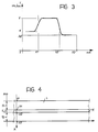
- the scale on the abscissa is given in centimetres of thickness of the product A, with the zero corresponding to the upper surface of the product, the points X 1 and X 2 corresponding to the interfaces between the various layers and the point X 3 corresponding to the plane P.
- the graph of Figure 3 relates to experiments carried out on a product for which X 1 , X 2 , and X 3 correspond to values of 5, 10 and 15 mm respectively.
- the respective values are 12, 17 and 29 mm on the other hand.
- the graph of Figure 6 however is intended to show how, for a given product structure, the optimum laws of variation of the cutting rate could change even significantly.
- EP-A-0 614 733 describes in detail how a motor, such as the motor 6 can be piloted selectively so as to vary selectively the velocity of an element driven by the motor itself through a rod and crank mechanism, for example to drive this element at a constant velocity.
Landscapes
- Life Sciences & Earth Sciences (AREA)
- Engineering & Computer Science (AREA)
- Forests & Forestry (AREA)
- Mechanical Engineering (AREA)
- Food Science & Technology (AREA)
- Confectionery (AREA)
- Formation And Processing Of Food Products (AREA)
- Perforating, Stamping-Out Or Severing By Means Other Than Cutting (AREA)
- Food-Manufacturing Devices (AREA)
- Manufacturing And Processing Devices For Dough (AREA)
- Control And Other Processes For Unpacking Of Materials (AREA)
- Preparation Of Fruits And Vegetables (AREA)
Abstract
Description
- The present invention relates to apparatus for cutting food products according to the preamble to
Claim 1. - Apparatus of this type is known, for example, from EP-A-0 614 733. This prior art document describes the presence of a pair of cutting devices (ultrasound blades) driven by a rod and crank mechanism on a member which can travel in synchronism with, and so as to follow food products which advance on a conveyor.
- This solution constitutes an example of the many conventional solutions used for cutting food products in industrial plants for the manufacture of such products. The operating criteria and types of such apparatus are in fact extremely varied.
- The automatic cutting of food products in such a context must take account of a series of factors which are becoming ever more important as conditions.
- In the first place, the productional capacities of such plants, and hence the rate at which it is necessary to carry out the cutting, tend to increase continuously.
- In the second place, the products treated are often delicate and cannot withstand very violent handling which could damage the product and/or cause the breaking away of fragments, crumbs and particles which can soil the plant itself.
- Yet again, many food products have an intrinsically non-homogeneous character in the sense that they are not constituted by a single food substance but rather by a combination of food substances which may be very different from each other: it suffices to think, for example, of filled and/or layered products.
- The object of the invention is to provide an apparatus which is able to satisfy all the requirements explained above in an excellent manner.
- According to the present invention this object is achieved by an apparatus having the characteristics claimed in
Claim 1. Advantageous developments of the invention form the subjects ofClaims 2 to 5. The invention also relates to the associated method having the characteristics claimed in Claim 6. Advantageous developments of this method constitute the subjects of subclaims 7 to 10. - The invention will now be described, purely by way of non-limitative example, with reference to the appended drawings, in which:
- Figure 1 is a schematic illustration of the structure of cutting apparatus according to the invention,
- Figure 2 illustrates the structure of a first food product which can be cut by an apparatus according to the invention,
- Figure 3 is a graph illustrating the mode of operation of the apparatus according to the invention during the cutting of the product illustrated in Figure 2,
- Figure 4 illustrates the structure of another food product which can be cut by the apparatus of the invention,
- Figure 5 is a graph illustrating the mode of operation of the apparatus of the invention during the cutting of the product illustrated in Figure 4, and
- Figure 6 illustrates a possible variant of the mode of operation referred to in Figure 5.
- Cutting apparatus according to the invention, generally indicated 1 in Figure 1, comprises essentially the following elements:
- a cutting element 2 (blade or knife) preferably having a sharp form and a structure typical of the so-calledsonotrode" of an ultrasonic welding or cutting apparatus,

- a unit 3 (of known type) for generating and conveying ultrasounds which is able to supply a wave front at ultrasonic frequency, that is so-calledultrasound", to the

blade 2 at a frequency typically of the order of 45 Khz, - a
drive mechanism 4 which imparts a reciprocating movement to the blade 2 (with a selectively regulable velocity as more fully described below) relative to a plane P on which food products A to be cut are arranged and usually advanced (in a manner substantially like that described in EP-A-0 614 733), and - a control unit 5 (for example a so-called PLC) which governs the operation of the
unit 3 and thedrive mechanism 4. - In the embodiment illustrated here, this latter mechanism includes a rotary motor 6, for example an electric motor, which rotates a wheel 7 which carries a
crank pin 8 at its periphery. One end of a connectingrod 9 is connected to thepin 8 while its opposite end acts on theblade 2 to reciprocate it along guide elements (indicated schematically at 10) arranged perpendicular to the plane P. This drive mechanism is substantially the same as the crank and connecting rod drive mechanism described in EP-A-0 614 733 to which reference may usefully be made for further constructional details. - The reference to this particular type of drive mechanism should however be considered as purely exemplary in that the solution of the invention lends itself to being carried out with drive mechanisms (drive) for the
blade 2 of very different types. To give several examples, one may consider linear drive mechanisms (including a movable member capable of imparting a reciprocating movement to theelement 2 relative to the plane P) which is operated hydraulically, electromagnetically, or piezoelectrically, etc. In each case, the constructional details of thedrive mechanism 4 for theblade 2 are not in themselves important for the purposes of carrying out the invention. - With reference to the crank and connecting rod mechanism described here by way of example, one may readily appreciate that, if the motor 6 is rotated at a constant angular velocity, the
element 2 will move with a harmonic motion relative to the plane P, that is, with a minimum velocity (in practice nil) at the end points, the so-called upper and lower dead points of its travel relative to the plane P, reaching maximum velocity at the median point of its travel. This is true in both directions of movement and, in particular, during its advancing movement, corresponding to its cutting action. It will readily be understood that, in this case, although the velocity of advance of theelement 2 varies locally, there is no possibility of varying this velocity selectively as the law governing the change of velocity with time (harmonic motion) is fixed. - The invention is based on a recognition of the fact that the basic requirements called for in the introduction to the specification may be satisfied almost ideally if recourse is made to the use, in combination, of an ultrasound cutting apparatus and a drive mechanism for the cutting element which is able to vary the speed of advance of the cutting element through the product A being cut selectively and locally (virtually point by point, whenever requirements necessitate it and, in any case, according to any law whatsoever, selected according to the applicational requirements).
- This is true particularly for the products A having non-homogeneous characteristics in the direction of cutting.
- Examples of products of this type are given in Figures 2 and 4.
- In both cases one is dealing with filled products with a layered structure.
- For example, Figure 2 shows a portion of a food product A including two layers of sponge S (possibly moistened with a sugar- or alcohol-based syrup) between which is a layer C of a creamy filling or paste constituted, for example, by a milk-flavoured cream.
- The product A illustrated in Figure 4, on the other hand, comprises an intermediate layer K of chocolate, mou (caramel) or like substance which is, on the whole, rather solid, interposed between two sponge layers S.
- Stated in other words, the two situations shown in Figures 2 and 4 are exactly complementary to each other. Indeed, in the product A of Figure 2, a generallysoft" layer C is interposed between the sponge layers S. In the case of the product A of Figure 4, however, a generallyhard" layer K is interposed between two sponge layers.
- The two examples of Figures 2 and 4 have been chosen appositely to illustrate two complementary situations. In any case, there is a practically infinite number of cases both with regard to products having fewer layers (for example, only two layers) and articles having more layers (which is the more frequent case): for example, as an illustration, a product such as that illustrated in Figure 2 having an upper coating of chocolate possibly with a granular material, such as chopped hazelnuts, shredded coconut, etc within it.
- The cutting systems most frequently used in the food sector, particularly in the confectionery sector, make use of mechanically-driven cutting elements, the automatic operation of which is designed to reproduce the cutting action that a baker or pastry chef can achieve with a kitchen knife or similar tool such as a bread knife.
- Experiments carried out by the applicant have shown, however, that these conventional solutions run the risk of being largely unsatisfactory for various reasons.
- For example, when a product A such as that illustrated in Figure 2 is cut with a purely mechanical action and it is wished to carry out the cutting extremely rapidly (one is talking of automatic cutters intended to operate in plants in which one is attempting to achieve as high an operating rate as possible), one of the more considerable risks is that of causing undesirable squashing of the soft filling layer C with the consequent possibility of the filling C spreading over the sides of the product, which is usually in the form of amat" of finite transverse dimensions (the so-calledsquish" effect).
- If one attempts to limit thissquish" effect while using conventional systems by advancing the blade slowly throughout the cutting operation, this does indeed avoid the squeezing out of the soft filling C, but the cutting operation is slowed considerably, with the consequent need to reduce the production rate.
- Then for thehard" layers, in addition to the possible squeezing of underlying softer layers, give rise to the further risk that, with too quick a movement down through this layer, it might splinter and form fragments and crumbs.
- Experiments carried out by the applicant have shown that
- in a wholly unexpected manner - the use of an ultrasound cutting element with a rate of advance that is variable selectively has shown to be beneficial both in relation to soft" layers and in relation tohard" layers. Even though the reasons for this are not entirely clear, one may hypothesise that, in the presence ofhard" layers, such as a layer of chocolate or like product, the ultrasound cutting element and the vibrational wave front propagated therefrom impinges on the layer to be cut so as to destructure it and hence separate it along the desired cutting line, slightly downstream (in the direction of advance) of the cutting element proper. In other words, the substance being cut starts to separate, and in fact separates, along the desired cutting line even before it is in fact acted on by the mechanical cutting action proper of the cutting element itself. This fact has been verified systematically by the Applicant, noting that improved cutting results occur when the ultrasound generator 3 (it is not usually activated continuously in order to avoid undesirable ultrasonic noise):
- is activated slightly before the tip of the
cutting element 2 actually touches the product A in its advance towards the product A, that is, when theelement 2 is still a certain distance away from the product A, and/or - when the
generator 3 is deactivated slightly before thecutting element 2 has terminated its advance towards the plane P on which the product A rests, that is, when theelement 2 is still a certain distance from the point P. - Even though it is difficult to provide absolute indications in this respect, the terma certain distance" should be understood, with reference to usual thicknesses of food products such as confectionary items subjected to cutting (typical thicknesses are from 1 to 3 cm approximately), as relating to magnitudes of the order of a millimetre/several millimetres.
- With regard to thesoft" layers, the fact that the
cutting element 2 is an ultrasound element has been found to be beneficial in that, with every probability of a microscopic shaking effect, the effects of adhesion of the material being cut to thecutting element 2 itself are minimised and virtually eliminated. This is true even for very adhesive or sticky materials, such as some food fillings (for example jam, icings, etc). - In a combined and synergic manner, the fact that there is virtually point control of the rate of advance of the
cutting element 2 enables this rate to be adapted to the characteristics of the layer being cut at any time, that is, in other words, the rate of advance of theultrasound cutting element 2 can be varied locally in dependence on the local characteristics (whether the layer is more or less hard or soft) of the product A in the zone (layer) cut at the moment. - A first result of this is that, in general, it is possible to advance quickly during the cutting of "soft" layers and slowly during the cutting of "hard" layers, thus without penalising the overall duration of the cutting operation as occurs in conventional systems where the rate of cutting is selected to be the minimum of those allowable for the various layers to be cut.
- Experiments carried out by the applicant have shown, however, that the criterion described above is not absolute and, in any case, the law of advance of the
cutting element 2 through the product A must be determined experimentally according to the characteristics of a product under consideration at any time. For example, the graphs of Figures 3 and 5 show, on the ordinates, the rates of advance (in cm/sec.) which have been shown to be optimum during the cutting of the products A shown in Figures 2 and 4 respectively. In both of the graphs of Figures 3 and 5, the scale on the abscissa is given in centimetres of thickness of the product A, with the zero corresponding to the upper surface of the product, the points X1 and X2 corresponding to the interfaces between the various layers and the point X3 corresponding to the plane P. - By way of example, the graph of Figure 3 relates to experiments carried out on a product for which X1, X2, and X3 correspond to values of 5, 10 and 15 mm respectively. In the graph of Figure 4, the respective values are 12, 17 and 29 mm on the other hand.
- From an examination of Figures 3 and 4 it may be noted, for example, that the law of variation of the rate of advance of the cutting
element 2 in the case of Figure 5 is not only different but in fact is quite the opposite of that achievable by operation of the motor 6 at a constant angular velocity. Another interesting fact is that (for reasons not yet fully clarified) structurally identical layers, such as the sponge layers S are cut in an optimum way at different speeds according to their positioning within the layered structure of the product. Again, it has been noted that it is advisable to avoid a sharp change in the rate of advance at the interfaces X1, X2 between the superposed layers in order to avoid any damage to the product. The changes between the various rates of advance are thus made (according to criteria known in the art of automatic control) in accordance with laws of connection, for example of the type currently definedat sine2". - The graph of Figure 6 however is intended to show how, for a given product structure, the optimum laws of variation of the cutting rate could change even significantly. For example, the graph of Figure 6 corresponds to the law of variation which has been found to be the optimum for a product such as that of Figure 4 in which X1 = 5 mm and X 3 = 28 mm. In this case it has been found that it is necessary to proceed very slowly (approximately 1 cm/s) at the beginning, when it is necessary to cut the sponge S while at the same time avoiding squashing the product. Subsequently it is possible to increase the rate of cutting gradually, recovering the delay which has accumulated from the slow cutting during the initial phase. EP-A-0 614 733 describes in detail how a motor, such as the motor 6 can be piloted selectively so as to vary selectively the velocity of an element driven by the motor itself through a rod and crank mechanism, for example to drive this element at a constant velocity.
- In more general terms, in the embodiment illustrated here, the operational link between the rate of rotation

blade 2 can be expressed by the equation
- R = radius of the path of the pin of the connecting
rod 8, - γ = crank angle (cfr. Figure 1), and
- π = connecting rod angle (cfr. Figure 1 again).
- The formula (I) given above shows, however, that, for each value of γ and β (values detectable in known manner by sensors), and hence for each instantaneous position reached by the
blade 2 relative to the plane P, it is possible to vary the angular velocity of the motor 6 selectively so as to impart a selectively determined velocity to theblade 2. All this may be achieved, according to criteria known per se, through suitable programming of thecontrol unit 5. The associated constructional and programming details are well known per se to experts in the art (particularly in the programming of PLCs) and do not need to be explained here in detail, especially since they are not relevant for the purposes of an understanding of the invention. - Naturally, the principle of the invention remaining the same, the constructional details and forms of embodiment may be varied widely with respect to that described and illustrated, without thereby departing from the scope of the invention.
Claims (10)
- Apparatus for cutting food products (A), including an ultrasound cutting element (2) with an associated drive mechanism (4 to 7) for selectively controlling the advance of the cutting element (2) through the product (A) being cut, characterised in that the drive mechanism (4) carries associated control means (5) arranged to control selectively the rate of advance of the cutting element (2) through the product (A) being cut and to vary the rate of advance locally in dependence on the local characteristics of the product (A) in the zone being cut at that moment.
- Apparatus according to Claim 1, characterised in that the ultrasound cutting element (2) operates at a frequency of around 45 Khz.
- Apparatus according to Claim 1 or Claim 2, characterised in that the cutting element (2) has an associated ultrasound source (3) that can be activated selectively so that it can be activated before the cutting element (2) comes into contact with the product (A) to be cut.
- Apparatus according to Claim 3, characterised in that the ultrasound source (3) can be deactivated before the cutting element (2) has completed its travel through the product (A) being cut.
- Apparatus according to any one of the preceding claims, characterised in that the drive mechanism comprises a connecting rod (9) driven by a crank (8) which is rotatable (7) by drive means (6) and in that control means (5) are provided for selectively controlling the rate of rotation of the drive means (6) so as to vary selectively the rate of advance of the cutting element (2) through the product (A) being cut.
- A method of cutting food products (A) by means of an ultrasound cutting element (2) with an associated drive mechanism (4 to 7) for advancing the cutting element (2) selectively through the product (A) being cut, characterised in that it includes a step of controlling the drive mechanism (4) so as to vary selectively the rate of advance of the cutting element (2) through the product (A) being cut, the rate of advance being modified locally in dependence on the local characteristics of the product (A) in the zone being cut at that moment.
- A method according to Claim 6, characterised in that it includes the step of supplying the ultrasound cutting element (2) so that it operates with ultrasound at a frequency of around 45 Khz.
- A method according to Claim 6 or Claim 7, characterised in that it includes the step of activating the ultrasound cutting element (2) selectively before the cutting element (2) comes into contact with the product (A) to be cut.
- A method according to Claim 8, characterised in that it includes the step of deactivating the ultrasound cutting element (2) before the cutting element (2) has completed its travel through the product (A) being cut.
- A method according to any one of the preceding Claims 6 to 9, characterised in that it includes the operation of associating with the ultrasound cutting element (2) a drive mechanism comprising a rod (9) driven by a crank (8) which is rotatable (7) by drive means (6) and in that it includes the step of controlling the rate of rotation of the drive means (6) selectively so as to vary selectively the rate of advance of the cutting element (2) through the product (A) being cut.
Applications Claiming Priority (3)
| Application Number | Priority Date | Filing Date | Title |
|---|---|---|---|
| CH01505/96A CH691023A5 (en) | 1996-06-17 | 1996-06-17 | Food product cutting apparatus e.g. for layered sponge cake |
| CH1505/96 | 1996-06-17 | ||
| CH150596 | 1996-06-17 |
Publications (3)
| Publication Number | Publication Date |
|---|---|
| EP0813937A2 true EP0813937A2 (en) | 1997-12-29 |
| EP0813937A3 EP0813937A3 (en) | 1998-05-06 |
| EP0813937B1 EP0813937B1 (en) | 2000-09-06 |
Family
ID=4212022
Family Applications (1)
| Application Number | Title | Priority Date | Filing Date |
|---|---|---|---|
| EP97109770A Expired - Lifetime EP0813937B1 (en) | 1996-06-17 | 1997-06-16 | Apparatus and method for cutting food products |
Country Status (17)
| Country | Link |
|---|---|
| US (1) | US5862728A (en) |
| EP (1) | EP0813937B1 (en) |
| JP (1) | JPH1052245A (en) |
| CN (1) | CN1170543A (en) |
| AT (1) | ATE196109T1 (en) |
| AU (1) | AU2481197A (en) |
| BR (1) | BR9702482A (en) |
| CA (1) | CA2207521A1 (en) |
| CH (1) | CH691023A5 (en) |
| CZ (1) | CZ186797A3 (en) |
| DE (1) | DE69703004T2 (en) |
| DK (1) | DK0813937T3 (en) |
| ES (1) | ES2151697T3 (en) |
| HU (1) | HUP9701054A3 (en) |
| PL (1) | PL320602A1 (en) |
| PT (1) | PT813937E (en) |
| SK (1) | SK76397A3 (en) |
Cited By (3)
| Publication number | Priority date | Publication date | Assignee | Title |
|---|---|---|---|---|
| EP1043939A4 (en) * | 1997-12-31 | 2004-10-06 | Mars Inc | Ultrasonically activated continuous slitter apparatus and method |
| EP2123162A2 (en) | 2008-05-09 | 2009-11-25 | Soremartec S.A. | Apparatus for filling a baked good |
| FR3107664A1 (en) * | 2020-03-02 | 2021-09-03 | Sodeva Tds | Ultrasonic cutting system |
Families Citing this family (25)
| Publication number | Priority date | Publication date | Assignee | Title |
|---|---|---|---|---|
| CH687241A5 (en) * | 1993-05-07 | 1996-10-31 | Walter Suter | Device for cutting continuous paper and a method for its operation. |
| US6145285A (en) * | 1998-09-28 | 2000-11-14 | Weiler Engineering, Inc. | Apparatus and method for molding a container and including a vibrating knife assembly |
| GB2350779B (en) * | 1999-06-09 | 2003-11-12 | Aew Eng Co Ltd | Improvements relating to the formation of uniform blocks of foodstuff |
| US6692782B1 (en) | 1999-10-19 | 2004-02-17 | The Pillsbury Company | Filled potato product |
| US6550361B1 (en) | 2000-06-14 | 2003-04-22 | Mead Westvaco Corporation | Platen die cutting monitoring system |
| US6662529B2 (en) * | 2001-09-26 | 2003-12-16 | Foodtools, Inc. | Ultrasonic method for dividing pastries and inserting dividers |
| US6684748B2 (en) * | 2001-12-31 | 2004-02-03 | George A. Mendenhall | Apparatus for cutting optimally sized fruit and vegetable pieces |
| US20040146616A1 (en) * | 2003-01-29 | 2004-07-29 | Thorson James S. | Method and system for ultrasonic surface modification of food products |
| US20050081692A1 (en) * | 2003-10-20 | 2005-04-21 | Kraft Foods Holdings, Inc. | Ultrasonic slitter |
| US20080289515A1 (en) * | 2007-04-17 | 2008-11-27 | Knorr Robert J | Pepper de-stemming |
| US8511226B2 (en) * | 2007-04-17 | 2013-08-20 | Robert J. Knorr | Pepper de-stemming methods and apparatus |
| US20100285187A1 (en) * | 2009-05-08 | 2010-11-11 | Weinstein James N | Apparatus and methods for cutting individual pieces from a food extrudate |
| WO2011130024A1 (en) * | 2010-04-12 | 2011-10-20 | Branson Ultrasonics Corporation | Ultrasonic system and method for cutting soft materials and ultrasonic horn blade therefor |
| EP2551077A1 (en) * | 2011-07-26 | 2013-01-30 | A O Schallinox GmbH | Blade for splitting goods for processing using ultrasound energy and device |
| DE102011118208A1 (en) * | 2011-11-11 | 2013-05-16 | Artech Ultrasonic Systems Ag | Ultrasonic cutter |
| CN103101073B (en) * | 2013-02-21 | 2015-09-16 | 苏州农业职业技术学院 | A kind of food masticator blocking material uniform length |
| CN103921299B (en) * | 2014-05-06 | 2015-07-22 | 安徽工程大学 | Ultrasonic wave food processing device |
| ES2830180T3 (en) * | 2015-06-08 | 2021-06-03 | Rheon Automatic Machinery Co | Forming method for dough pieces and forming apparatus for the same |
| CN106889135A (en) * | 2017-04-19 | 2017-06-27 | 常州机电职业技术学院 | Cake slicing machine |
| US11191281B1 (en) | 2018-01-05 | 2021-12-07 | Tyson Foods, Inc. | Method and apparatus for conveying a meat product and using an ultrasonic knife for automated cutting of meat |
| US11944105B1 (en) | 2018-01-05 | 2024-04-02 | Tyson Foods, Inc. | Method and apparatus for conveying a meat product and using a knife for automated cutting of meat |
| CN108308225A (en) * | 2018-05-10 | 2018-07-24 | 广州浩胜弘裕机械设备有限公司 | Ultrasonic wave cake cutting machine |
| KR102186493B1 (en) * | 2019-02-18 | 2020-12-03 | 송철규 | Ultrasonic Bread Cutter |
| US11751598B2 (en) | 2019-05-08 | 2023-09-12 | Agile Innovation, Inc. | Smart cutter for high speed produce processing |
| CN111066865A (en) * | 2019-12-17 | 2020-04-28 | 安徽恒盛实业有限责任公司 | Beef cutting device |
Family Cites Families (12)
| Publication number | Priority date | Publication date | Assignee | Title |
|---|---|---|---|---|
| GB1177064A (en) * | 1966-04-15 | 1970-01-07 | Chambon Ltd | Improvements in or relating to Knives |
| US3680616A (en) * | 1970-04-06 | 1972-08-01 | Pillsbury Co | Method and apparatus for severing food products |
| GB1354505A (en) * | 1970-09-09 | 1974-05-30 | Cadbury Ltd | Method of and apparatus for cutting a blanket of confectionery product |
| US4299150A (en) * | 1979-05-31 | 1981-11-10 | General Mills, Inc. | Method and apparatus for severing portions from a plurality of frozen columns of fish or the like |
| JPH01143211A (en) * | 1987-11-27 | 1989-06-05 | Takatori Haitetsuku:Kk | Sticking and cutting of protective tape for wafer and device therefor |
| ATE102862T1 (en) * | 1989-11-25 | 1994-04-15 | Frisco Findus Ag | CUTTING DEVICE FOR FOOD. |
| DK0504466T3 (en) * | 1991-03-22 | 1994-03-21 | Frisco Findus Ag | Apparatus and process for cutting |
| US5163865A (en) * | 1991-05-08 | 1992-11-17 | Innerspace Technologies Of Alaska, Inc. | Method and apparatus for processing fish fillets and other food items into predetermined portions |
| US5243888A (en) * | 1991-09-17 | 1993-09-14 | Bowlin William P | Pivoting carriage and saw |
| GB9124762D0 (en) * | 1991-11-21 | 1992-01-15 | Unilever Plc | Food cutting process |
| GB2270025A (en) * | 1992-08-28 | 1994-03-02 | Nestle Sa | Ultrasonic cutting |
| CH688308A5 (en) * | 1993-03-12 | 1997-07-31 | Soremartec Sa | synchronization device, particularly for installations for the manufacture and the packaging of food products. |
-
1996
- 1996-06-17 CH CH01505/96A patent/CH691023A5/en not_active IP Right Cessation
-
1997
- 1997-06-10 CA CA002207521A patent/CA2207521A1/en not_active Abandoned
- 1997-06-11 AU AU24811/97A patent/AU2481197A/en not_active Abandoned
- 1997-06-13 US US08/874,284 patent/US5862728A/en not_active Expired - Fee Related
- 1997-06-13 SK SK763-97A patent/SK76397A3/en unknown
- 1997-06-16 EP EP97109770A patent/EP0813937B1/en not_active Expired - Lifetime
- 1997-06-16 DE DE69703004T patent/DE69703004T2/en not_active Expired - Fee Related
- 1997-06-16 DK DK97109770T patent/DK0813937T3/en active
- 1997-06-16 JP JP9158425A patent/JPH1052245A/en active Pending
- 1997-06-16 PT PT97109770T patent/PT813937E/en unknown
- 1997-06-16 HU HU9701054A patent/HUP9701054A3/en unknown
- 1997-06-16 AT AT97109770T patent/ATE196109T1/en not_active IP Right Cessation
- 1997-06-16 ES ES97109770T patent/ES2151697T3/en not_active Expired - Lifetime
- 1997-06-17 CZ CZ971867A patent/CZ186797A3/en unknown
- 1997-06-17 BR BR9702482A patent/BR9702482A/en not_active Application Discontinuation
- 1997-06-17 CN CN97114820A patent/CN1170543A/en active Pending
- 1997-06-17 PL PL97320602A patent/PL320602A1/en unknown
Cited By (5)
| Publication number | Priority date | Publication date | Assignee | Title |
|---|---|---|---|---|
| EP1043939A4 (en) * | 1997-12-31 | 2004-10-06 | Mars Inc | Ultrasonically activated continuous slitter apparatus and method |
| EP2123162A2 (en) | 2008-05-09 | 2009-11-25 | Soremartec S.A. | Apparatus for filling a baked good |
| EP2123162A3 (en) * | 2008-05-09 | 2010-02-03 | Soremartec S.A. | Apparatus for filling a baked good |
| FR3107664A1 (en) * | 2020-03-02 | 2021-09-03 | Sodeva Tds | Ultrasonic cutting system |
| EP3875233A1 (en) * | 2020-03-02 | 2021-09-08 | Sodeva Tds | Ultrasound cutting system |
Also Published As
| Publication number | Publication date |
|---|---|
| AU2481197A (en) | 1998-01-08 |
| ATE196109T1 (en) | 2000-09-15 |
| CZ186797A3 (en) | 1998-01-14 |
| ES2151697T3 (en) | 2001-01-01 |
| HUP9701054A2 (en) | 1998-05-28 |
| US5862728A (en) | 1999-01-26 |
| BR9702482A (en) | 1998-09-15 |
| HU9701054D0 (en) | 1997-08-28 |
| MX9704471A (en) | 1998-06-28 |
| HUP9701054A3 (en) | 1998-06-29 |
| DE69703004D1 (en) | 2000-10-12 |
| PL320602A1 (en) | 1997-12-22 |
| DE69703004T2 (en) | 2001-06-07 |
| DK0813937T3 (en) | 2000-11-13 |
| JPH1052245A (en) | 1998-02-24 |
| CA2207521A1 (en) | 1997-12-17 |
| CH691023A5 (en) | 2001-04-12 |
| PT813937E (en) | 2000-12-29 |
| CN1170543A (en) | 1998-01-21 |
| SK76397A3 (en) | 1998-06-03 |
| EP0813937A3 (en) | 1998-05-06 |
| EP0813937B1 (en) | 2000-09-06 |
Similar Documents
| Publication | Publication Date | Title |
|---|---|---|
| EP0813937B1 (en) | Apparatus and method for cutting food products | |
| US4692109A (en) | Apparatus for cutting filled cylindrical dough body | |
| US6032561A (en) | Apparatus for ultrasonic cutting of food products | |
| US6058823A (en) | Ultrasonic cutting device | |
| EP3305077B1 (en) | Shaping method for dough pieces and shaping apparatus for same | |
| KR100448729B1 (en) | Ultrasonic full-width sheeter | |
| US5819615A (en) | Cutting process | |
| EP2996847B1 (en) | Device for cutting a process material using ultrasound and cuting method | |
| US4643904A (en) | Method of increasing the visibility of discrete morsels contained within a baked food product | |
| CA2220073A1 (en) | Method and apparatus for cutting dough products | |
| US4697505A (en) | Apparatus for increasing the visibility of discrete morsels contained within a baked food product | |
| EP0543628A1 (en) | Food processing | |
| KR100249745B1 (en) | Method and apparatus for making embossed-brim products | |
| US4344341A (en) | Slicing apparatus | |
| JPH03277497A (en) | Ultrasonic cutting device for kind of bread, processed meat product and the like | |
| JP2759302B2 (en) | Apparatus for cutting continuously supplied strip material to predetermined length | |
| JP2565393Y2 (en) | Ultrasonic cutting equipment for bread and meat storage products | |
| HK1008168A (en) | Apparatus and method for cutting food products | |
| CN214802027U (en) | DD directly drives motor numerical control meat cutting machine | |
| CN223777294U (en) | Cutting device for baked food processing | |
| MXPA97004471A (en) | Device for the cutting of foodstuffs and procedure for the cutting of mis | |
| Navaneetha et al. | A Review on Development of Automated Cutter with Multiple Blades for Baked Products | |
| JPS5826302B2 (en) | Molding method | |
| JPH09103989A (en) | Cutter of single-direction stroke | |
| US20020050066A1 (en) | Cutting blade |
Legal Events
| Date | Code | Title | Description |
|---|---|---|---|
| PUAI | Public reference made under article 153(3) epc to a published international application that has entered the european phase |
Free format text: ORIGINAL CODE: 0009012 |
|
| AK | Designated contracting states |
Kind code of ref document: A2 Designated state(s): AT BE CH DE DK ES FI FR GB IE IT LI LU MC NL PT SE |
|
| AX | Request for extension of the european patent |
Free format text: AL;LT;LV;SI |
|
| PUAL | Search report despatched |
Free format text: ORIGINAL CODE: 0009013 |
|
| AK | Designated contracting states |
Kind code of ref document: A3 Designated state(s): AT BE CH DE DK ES FI FR GB GR IE IT LI LU MC NL PT SE |
|
| AX | Request for extension of the european patent |
Free format text: AL;LT;LV;SI |
|
| 17P | Request for examination filed |
Effective date: 19981022 |
|
| AKX | Designation fees paid |
Free format text: AT BE CH DE DK ES FI FR GB GR IE IT LI LU MC NL PT |
|
| RBV | Designated contracting states (corrected) |
Designated state(s): AT BE CH DE DK ES FI FR GB GR IE IT LI LU MC NL PT |
|
| GRAG | Despatch of communication of intention to grant |
Free format text: ORIGINAL CODE: EPIDOS AGRA |
|
| 17Q | First examination report despatched |
Effective date: 19990427 |
|
| RBV | Designated contracting states (corrected) |
Designated state(s): AT BE CH DE DK ES FI FR GB IE IT LI LU MC NL PT SE |
|
| GRAG | Despatch of communication of intention to grant |
Free format text: ORIGINAL CODE: EPIDOS AGRA |
|
| GRAH | Despatch of communication of intention to grant a patent |
Free format text: ORIGINAL CODE: EPIDOS IGRA |
|
| GRAH | Despatch of communication of intention to grant a patent |
Free format text: ORIGINAL CODE: EPIDOS IGRA |
|
| GRAA | (expected) grant |
Free format text: ORIGINAL CODE: 0009210 |
|
| RAP1 | Party data changed (applicant data changed or rights of an application transferred) |
Owner name: FERRERO OFFENE HANDELSGESELLSCHAFT M.B.H. Owner name: FERRERO S.P.A. Owner name: SOREMARTEC S.A. |
|
| AK | Designated contracting states |
Kind code of ref document: B1 Designated state(s): AT BE CH DE DK ES FI FR GB IE IT LI LU MC NL PT SE |
|
| PG25 | Lapsed in a contracting state [announced via postgrant information from national office to epo] |
Ref country code: SE Free format text: LAPSE BECAUSE OF FAILURE TO SUBMIT A TRANSLATION OF THE DESCRIPTION OR TO PAY THE FEE WITHIN THE PRESCRIBED TIME-LIMIT Effective date: 20000906 |
|
| REF | Corresponds to: |
Ref document number: 196109 Country of ref document: AT Date of ref document: 20000915 Kind code of ref document: T |
|
| ITF | It: translation for a ep patent filed | ||
| REG | Reference to a national code |
Ref country code: CH Ref legal event code: EP |
|
| REG | Reference to a national code |
Ref country code: CH Ref legal event code: NV Representative=s name: JACOBACCI & PERANI S.A. |
|
| REF | Corresponds to: |
Ref document number: 69703004 Country of ref document: DE Date of ref document: 20001012 |
|
| ET | Fr: translation filed | ||
| REG | Reference to a national code |
Ref country code: IE Ref legal event code: FG4D |
|
| REG | Reference to a national code |
Ref country code: DK Ref legal event code: T3 |
|
| REG | Reference to a national code |
Ref country code: PT Ref legal event code: SC4A Free format text: AVAILABILITY OF NATIONAL TRANSLATION Effective date: 20000908 |
|
| REG | Reference to a national code |
Ref country code: ES Ref legal event code: FG2A Ref document number: 2151697 Country of ref document: ES Kind code of ref document: T3 |
|
| PGFP | Annual fee paid to national office [announced via postgrant information from national office to epo] |
Ref country code: AT Payment date: 20010510 Year of fee payment: 5 |
|
| PGFP | Annual fee paid to national office [announced via postgrant information from national office to epo] |
Ref country code: IE Payment date: 20010521 Year of fee payment: 5 |
|
| PG25 | Lapsed in a contracting state [announced via postgrant information from national office to epo] |
Ref country code: LU Free format text: LAPSE BECAUSE OF NON-PAYMENT OF DUE FEES Effective date: 20010616 Ref country code: FI Free format text: LAPSE BECAUSE OF NON-PAYMENT OF DUE FEES Effective date: 20010616 Ref country code: DK Free format text: LAPSE BECAUSE OF NON-PAYMENT OF DUE FEES Effective date: 20010616 |
|
| PG25 | Lapsed in a contracting state [announced via postgrant information from national office to epo] |
Ref country code: ES Free format text: LAPSE BECAUSE OF NON-PAYMENT OF DUE FEES Effective date: 20010617 |
|
| PG25 | Lapsed in a contracting state [announced via postgrant information from national office to epo] |
Ref country code: MC Free format text: LAPSE BECAUSE OF NON-PAYMENT OF DUE FEES Effective date: 20010630 Ref country code: LI Free format text: LAPSE BECAUSE OF NON-PAYMENT OF DUE FEES Effective date: 20010630 Ref country code: CH Free format text: LAPSE BECAUSE OF NON-PAYMENT OF DUE FEES Effective date: 20010630 |
|
| PLBE | No opposition filed within time limit |
Free format text: ORIGINAL CODE: 0009261 |
|
| STAA | Information on the status of an ep patent application or granted ep patent |
Free format text: STATUS: NO OPPOSITION FILED WITHIN TIME LIMIT |
|
| 26N | No opposition filed | ||
| PG25 | Lapsed in a contracting state [announced via postgrant information from national office to epo] |
Ref country code: PT Free format text: LAPSE BECAUSE OF NON-PAYMENT OF DUE FEES Effective date: 20011231 |
|
| PG25 | Lapsed in a contracting state [announced via postgrant information from national office to epo] |
Ref country code: NL Free format text: LAPSE BECAUSE OF NON-PAYMENT OF DUE FEES Effective date: 20020101 |
|
| REG | Reference to a national code |
Ref country code: GB Ref legal event code: IF02 |
|
| EUG | Se: european patent has lapsed |
Ref document number: 97109770.4 |
|
| REG | Reference to a national code |
Ref country code: CH Ref legal event code: PL |
|
| REG | Reference to a national code |
Ref country code: DK Ref legal event code: EBP |
|
| NLV4 | Nl: lapsed or anulled due to non-payment of the annual fee |
Effective date: 20020101 |
|
| REG | Reference to a national code |
Ref country code: PT Ref legal event code: MM4A Free format text: LAPSE DUE TO NON-PAYMENT OF FEES Effective date: 20011231 |
|
| PG25 | Lapsed in a contracting state [announced via postgrant information from national office to epo] |
Ref country code: AT Free format text: LAPSE BECAUSE OF NON-PAYMENT OF DUE FEES Effective date: 20020616 |
|
| PG25 | Lapsed in a contracting state [announced via postgrant information from national office to epo] |
Ref country code: IE Free format text: LAPSE BECAUSE OF NON-PAYMENT OF DUE FEES Effective date: 20020617 |
|
| REG | Reference to a national code |
Ref country code: IE Ref legal event code: MM4A |
|
| REG | Reference to a national code |
Ref country code: ES Ref legal event code: FD2A Effective date: 20020711 |
|
| PGFP | Annual fee paid to national office [announced via postgrant information from national office to epo] |
Ref country code: BE Payment date: 20080606 Year of fee payment: 12 Ref country code: IT Payment date: 20080625 Year of fee payment: 12 |
|
| PGFP | Annual fee paid to national office [announced via postgrant information from national office to epo] |
Ref country code: DE Payment date: 20080626 Year of fee payment: 12 |
|
| PGFP | Annual fee paid to national office [announced via postgrant information from national office to epo] |
Ref country code: FR Payment date: 20080630 Year of fee payment: 12 |
|
| PGFP | Annual fee paid to national office [announced via postgrant information from national office to epo] |
Ref country code: GB Payment date: 20080521 Year of fee payment: 12 |
|
| BERE | Be: lapsed |
Owner name: S.A. *SOREMARTEC Effective date: 20090630 |
|
| GBPC | Gb: european patent ceased through non-payment of renewal fee |
Effective date: 20090616 |
|
| REG | Reference to a national code |
Ref country code: FR Ref legal event code: ST Effective date: 20100226 |
|
| PG25 | Lapsed in a contracting state [announced via postgrant information from national office to epo] |
Ref country code: FR Free format text: LAPSE BECAUSE OF NON-PAYMENT OF DUE FEES Effective date: 20090630 |
|
| PG25 | Lapsed in a contracting state [announced via postgrant information from national office to epo] |
Ref country code: GB Free format text: LAPSE BECAUSE OF NON-PAYMENT OF DUE FEES Effective date: 20090616 |
|
| PG25 | Lapsed in a contracting state [announced via postgrant information from national office to epo] |
Ref country code: DE Free format text: LAPSE BECAUSE OF NON-PAYMENT OF DUE FEES Effective date: 20100101 Ref country code: BE Free format text: LAPSE BECAUSE OF NON-PAYMENT OF DUE FEES Effective date: 20090630 |
|
| PG25 | Lapsed in a contracting state [announced via postgrant information from national office to epo] |
Ref country code: IT Free format text: LAPSE BECAUSE OF NON-PAYMENT OF DUE FEES Effective date: 20090616 |