EP0812059A1 - Control process for a rotary machine, servosystem for carrying out this process and rotary machine with such a system - Google Patents
Control process for a rotary machine, servosystem for carrying out this process and rotary machine with such a system Download PDFInfo
- Publication number
- EP0812059A1 EP0812059A1 EP97401181A EP97401181A EP0812059A1 EP 0812059 A1 EP0812059 A1 EP 0812059A1 EP 97401181 A EP97401181 A EP 97401181A EP 97401181 A EP97401181 A EP 97401181A EP 0812059 A1 EP0812059 A1 EP 0812059A1
- Authority
- EP
- European Patent Office
- Prior art keywords
- computer
- ref
- stator
- vector
- phase voltage
- Prior art date
- Legal status (The legal status is an assumption and is not a legal conclusion. Google has not performed a legal analysis and makes no representation as to the accuracy of the status listed.)
- Granted
Links
Images


Classifications
-
- H—ELECTRICITY
- H02—GENERATION; CONVERSION OR DISTRIBUTION OF ELECTRIC POWER
- H02P—CONTROL OR REGULATION OF ELECTRIC MOTORS, ELECTRIC GENERATORS OR DYNAMO-ELECTRIC CONVERTERS; CONTROLLING TRANSFORMERS, REACTORS OR CHOKE COILS
- H02P23/00—Arrangements or methods for the control of AC motors characterised by a control method other than vector control
- H02P23/30—Direct torque control [DTC] or field acceleration method [FAM]
-
- H—ELECTRICITY
- H02—GENERATION; CONVERSION OR DISTRIBUTION OF ELECTRIC POWER
- H02P—CONTROL OR REGULATION OF ELECTRIC MOTORS, ELECTRIC GENERATORS OR DYNAMO-ELECTRIC CONVERTERS; CONTROLLING TRANSFORMERS, REACTORS OR CHOKE COILS
- H02P21/00—Arrangements or methods for the control of electric machines by vector control, e.g. by control of field orientation
- H02P21/24—Vector control not involving the use of rotor position or rotor speed sensors
- H02P21/28—Stator flux based control
- H02P21/30—Direct torque control [DTC] or field acceleration method [FAM]
Definitions
- the invention relates to a process for controlling and controlling a rotating machine, a control system for implementing said method, and a rotating machine provided with such a system. More specifically, the present invention relates to a torque and stator flow control method for a rotating machine.
- PWM pulse width modulator
- control quantities are the electromagnetic couple and the stator flux. This method no longer requires PWM.
- This method involves vector modeling of the machine and the voltage inverter.
- the electromagnetic torque is a function of the angle existing between the rotating rotor flux vector and the stator flux rotating vector and the modules of these flux vectors.
- the stator voltage vector V s is delivered by a three-phase voltage inverter each phase comprising a two-state switch (SP2LL: Single Pole 2 Logic Levels / single pole with 2 logical levels). Therefore, the stator voltage vector V s can take 8 states V 1 ... V 8 (2 3 ), including two V 1 , V 8 of zero amplitude (zero states) in the fixed stator frame ( ⁇ , ⁇ ), depending on the combination of the three SP2LLs of the inverter.
- SP2LL Single Pole 2 Logic Levels / single pole with 2 logical levels
- Fig. 1 a system called DTC (Direct Torque Control) based, in the stator frame ( ⁇ , ⁇ ), on the maintenance of the module
- DTC Direct Torque Control
- the control of the stator flux vector ⁇ s is ensured by means of a finite table.
- the finished table below and figure 1 illustrates this method.
- ⁇ s is in the area N 6 and its end follows the state V 2 of the stator phase voltage vector V s .
- the state V 2 is a state which makes grow
- the process will switch to V 3 as soon as
- One of the aims of the present invention is to propose a method where, the control quantities also being the electromagnetic torque and the stator flux, whatever the situation of the rotating machine at a given time, the state of the optimal stator phase voltage vector V s , among all possible states, to best respond to the desired control strategy.
- the invention has the other advantage that when one of the SPmLLs is accidentally blocked in a position which is not optimal for a given configuration, the method will continue to choose the best possible state among the remaining possible states to reconcile instructions. The dynamic performance of control are affected, but the risk of discrepancies or peak torque is minimized.
- Controlling the average switching frequency of the inverter is an advantage which makes it possible to significantly limit the switching losses in SPmLLs and therefore extend their service life.
- the invention also relates to a servo system implementing the method described above.
- the invention finally relates to a rotary machine comprising such a servo system.
- Figure 1 is a schematic representation in the fixed stator plane of the method of the prior art.
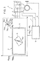
- Figure 2 is a schematic representation of the method according to the invention for a transient regime.
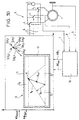
- Figures 3 to 3E are schematic representations of the method according to the invention for an established regime, from a given example cycle.
- the invention relates to a method for regulating a rotating machine 1 to n Phases supplied with alternating current by means of a voltage inverter 3 comprising n switches with m positions 4 (hereinafter SPmLL: Single Pole m Logic Levels / single pole with m logic levels) defining m n states V i (i ⁇ ⁇ 1, .., m n ⁇ ) of the stator phase voltage vector V s , said machine 1 being controlled by an electromagnetic torque T em ref and to a stator flux ⁇ S ref setpoint.
- SPmLL Single Pole m Logic Levels / single pole with m logic levels
- the control system of the machine comprises a set of sensors whose sensed values 7, 8, 9 are transmitted to an observer 10.
- the outputs of the observer 10 are values representative of the electromechanical couple T em and of the stator flux ⁇ S of the rotating machine. There are many more or less sophisticated sensors and observers 10.
- the values representative of the electromagnetic torque T em and of the stator flux ⁇ s are injected into the computer 13 implementing the method according to the invention.
- This computer 13 also receives as inputs the values representative of the setpoints T em ref , ⁇ S ref electromechanical torque and stator flow.
- the computer 13 outputs the control signals 6 intended to control the SPmLLs 4 of the voltage inverter 3.
- the invention relates more precisely to the process steps taking place in the computer 13.
- an output plane P is constructed in the computer 13, one of the axes of which is representative of the electromagnetic torque and the other x axis is representative of the stator flux, it defines a point a ref representing instructions torque and stator flux in said plane and a point a representing the instantaneous configuration of the machine, is defined around the point a ref part of plane 5 ⁇ ⁇ x, ⁇ ⁇ y inside which one is in steady state, and outside which one is in transient state. Therefore plan P is divided into two parts, each representing one of the plans.
- the method chooses from the set of possible states V i (i ⁇ ⁇ 1, .., m n ⁇ ) of the stator phase voltage vector V s that which offers the greatest speed of variation from point A in a direction close to the ideal direction (AA ref ) of approach.
- FIG. 2 represents the operation of the process in transient regime.
- the dotted line 15 represents the ideal path for A to join A ref as quickly as possible.
- the vector (AA ref ) is recalculated as well as the optimal state. This can result, for example, in a trajectory as represented by curve 14.
- FIGS. 3A to 3E as well as the switching table below represent an example of implementation of the steady state process Figure 3 shows the cycle 15 chosen.
- FIGS. 3A to 3E as well as the table above shows an example of circulation of point A according to the cycle 15 chosen.
- the positioning and dimensioning of the zones Z i have an influence on the average switching frequency of the inverter and vice versa.
- the average frequency of switching of the inverter is taken into consideration during the construction of the zones Z i .
- Controlling the average switching frequency of the inverter is an advantage which considerably limits the risks of damage to the SPmLLs and extends their service life.
- point A is either in zone Z 2 or in zone Z 4 , the current state is V 3 , the past state is V 2 .
- Point A may, in the future, pass into zone Z 5 , Z 1 , or Z 3 .
- the future state will remain the current state V 3 , if point A passes through one of the zones Z 5 , Z 1 , or Z 3 , the future state is V 1 .
- FIGS 3B to 3E can be explained in the same way using the switch table.
- the y-axis directly represents the electromagnetic torque
- the x-axis represents the square of the stator flux.
- the points of the plane P have the coordinates: ( ⁇ s 2 / ⁇ o 2 , ( ⁇ -1) T em / T o ) where ⁇ is a weighting coefficient whose value is set by the user of the rotating machine. This weighting coefficient makes it possible to give a more or less significant weight to one of the outputs compared to the other.
- the invention also relates to a servo system implementing the method described above.
- the invention finally relates to a rotary machine comprising such a servo system.
- the invention is not limited to the embodiment described and shown, but it is capable of numerous variants accessible to a person skilled in the art without that we depart from the invention.
- the three SP2LL can be replaced by n SPmLL without departing from the scope of the invention.
Abstract
Description
L'invention concerne un procédé de contrôle commande d'une machine tournante, un système d'asservissement pour mettre en oeuvre ledit procédé, et une machine tournante pourvue d'un tel système. Plus précisément la présente invention concerne un procédé de contrôle en couple et en flux statorique d'une machine tournante.The invention relates to a process for controlling and controlling a rotating machine, a control system for implementing said method, and a rotating machine provided with such a system. More specifically, the present invention relates to a torque and stator flow control method for a rotating machine.
On connaît des dispositifs de contrôle vectoriel du flux rotorique. Ce contrôle se base sur un contrôle effectif de l'état magnétique du rotor et du couple de la machine. Cependant ce type de dispositif nécessite la mise en place de capteur sur les parties tournantes de la machine afin de capter une grandeur mécanique nécessaire au calcul. En outre, ces dispositifs restent très sensibles aux variations de paramètres de la machine. Enfin ces dispositifs nécessitent l'utilisation de modulateur du type à largeur d'impulsions (MLI) qui entraîne un retard au niveau du temps de réponse de la machine lors d'un échelon en couple ou en vitesse.Devices for vector control of the rotor flow are known. This control is based on an effective control of the magnetic state of the rotor and the torque of the machine. However, this type of device requires the installation of a sensor on the rotating parts of the machine in order to capture a mechanical quantity necessary for the calculation. In addition, these devices remain very sensitive to variations in machine parameters. Finally, these devices require the use of a pulse width modulator (PWM) which causes a delay in the response time of the machine during a torque or speed step.
On connaît une méthode alternative où les grandeurs de contrôle sont le couple électromagnétique et le flux statorique. Cette méthode ne nécessite plus de MLI.An alternative method is known where the control quantities are the electromagnetic couple and the stator flux. This method no longer requires PWM.
Cette méthode passe par la modélisation vectorielle de la machine et de l'onduleur de tension.This method involves vector modeling of the machine and the voltage inverter.
Pour la machine on sait que le couple électromagnétique est fonction de l'angle existant entre le vecteur tournant flux rotorique et le vecteur tournant flux statorique et les modules de ces vecteurs flux. Autrement dit le couple électromagnétique est fonction du produit vectoriel des vecteurs flux tournant :![]()
![]()
Le vecteur tension stator Vs est délivré par un onduleur de tension triphasée chaque phase comprenant un interrupteur à deux états (SP2LL : Single Pole 2 Logic Levels / pôle unique à 2 niveaux logiques). De ce fait, le vecteur tension stator Vs peut prendre 8 états V1...V8 (23), dont deux V1, V8 d'amplitude nulles (états nuls) dans le repère fixe statorique (α, β), en fonction de la combinaison des trois SP2LL de l'onduleur.The stator voltage vector V s is delivered by a three-phase voltage inverter each phase comprising a two-state switch (SP2LL: Single Pole 2 Logic Levels / single pole with 2 logical levels). Therefore, the stator voltage vector V s can take 8 states V 1 ... V 8 (2 3 ), including two V 1 , V 8 of zero amplitude (zero states) in the fixed stator frame (α, β ), depending on the combination of the three SP2LLs of the inverter.
On connaît (Fig. 1) un système dit DTC (Direct Torque Control) reposant, dans le repère statorique (α, β), sur le maintien du module |φs| du vecteur tournant de flux statorique φs dans une bande d'hystérésis H, et sur le contrôle du couple Tem en accélérant le vecteur tournant de flux statorique φs par rapport au vecteur de flux rotorique φR pour une augmentation du couple Tem (augmentation de l'angle entre les deux vecteurs de flux) et en arrêtant le vecteur de flux statorique φs pour que le vecteur de flux rotorique φR le rattrape pour diminuer le couple (diminution de l'angle entre les deux vecteurs de flux).We know (Fig. 1) a system called DTC (Direct Torque Control) based, in the stator frame (α, β), on the maintenance of the module | φ s | of the rotating stator flux vector φ s in a hysteresis band H, and on the control of the torque T em by accelerating the rotating stator flux vector φ s relative to the rotor flux vector φ R for an increase in the torque T em (increase of the angle between the two flux vectors) and by stopping the stator flux vector φ s so that the rotor flux vector φ R catches it to decrease the torque (decrease of the angle between the two flux vectors ).
Le contrôle du vecteur de flux statorique φs est assuré par l'intermédiaire d'une table finie. Cette table contient, pour une localisation Ni (i = 1...6) donnée du vecteur de flux statorique φs tournant dans le plan du stator (α, β), les états V1...V8 du vecteur tension de phase stator Vs qui permettent d'arrêter le vecteur flux statorique (états nuls V1, V8), et ceux qui permettent d'ouvrir l'angle entre les vecteurs de flux φs, φR, tout en maintenant le vecteur de flux statorique φs dans la bande d'hystérésis H. la table finie ci-dessous et la figure 1 illustre cette méthode.

Par exemple dans la figure 1, φs est dans la zone N6 et son extrémité suit l'état V2 du vecteur tension de phase stator Vs. L'état V2 est un état qui fait croître |φs| le procédé commutera sur V3 dès que |φs| aura atteint la limite supérieure de la bande d'hystérésis H.For example in FIG. 1, φ s is in the area N 6 and its end follows the state V 2 of the stator phase voltage vector V s . The state V 2 is a state which makes grow | φ s | the process will switch to V 3 as soon as | φ s | will have reached the upper limit of the hysteresis band H.
Cette technique a plusieurs inconvénients à savoir :
- * La table finie n'est pas exhaustive des situations dynamiques possibles de la machine tournante. Concevoir une table en vu d'une prise en compte exhaustive des situations de la machine est inconcevable (dans le cas simple d'un onduleur à trois SP2LL on obtient déjà six domaines dans chacun desquels 4 états peuvent être utilisés). En outre, un défaut de fonctionnement de l'un des SP2LL supprime trois des états possibles du vecteur de phase statorique Vs ce qui réduit sensiblement la table finie de commande et peut amener la machine tournante dans une situation incontrôlable (pointe de couple).
- * La technique proposée dédie le contrôle du flux statorique φs (maintien du module du flux statorique dans la bande d'hystérésis H) au Contrôle du couple Tem. Les configurations dans lesquelles on souhaite un contrôle du Flux statorique φs concomitant au contrôle du couple Tem ne sont pas prévues.
- * Dans le cas d'un échelon de couple négatif (réduction du couple en échelon) à faible vitesse de rotation du rotor, la dynamique de réponse de la solution ci-dessus est très mauvaise. Notamment, le temps de réponse à de l'échelon négatif est de l'ordre de quatre fois le temps de réponse d'un échelon positif de même amplitude.
En effet, dans une configuration de réduction du couple, le dispositif arrête la rotation du flux statorique (état nul) et le flux rotorique rattrape le flux statorique réduisant de ce fait l'angle et donc le couple. Lorsque l'on est à faible vitesse de rotation du moteur, le flux rotorique tourne, lui aussi, à faible vitesse, ce qui affecte sensiblement la dynamique de réponse en couple.
Cette configuration à faible vitesse de rotation peut être illustrée par le démarrage d'une motrice, la mauvaise dynamique par un patinage des roues de la motrice (réduction de couple trop lente). - * La stratégie de commutation de l'onduleur de tension est la même que l'on soit en régime transitoire (les valeurs instantanées du flux et du couple sont éloignées des valeurs de consigne) ou en régime établi (les valeurs instantanées du flux et du couple oscillent autour des valeurs de consigne). De ce fait la fréquence moyenne de découpage de l'onduleur de tension, en régime établi, n'est pas contrôlable et chaotique. Pour des tensions et des courants maximaux élevés cela peut amener rapidement à une détérioration irréversible de certains SP2LL et donc, pour les raisons précédemment cités, amener la machine tournante dans une situation incontrôlable.
- * The finished table is not exhaustive of the possible dynamic situations of the rotating machine. Designing a table with a view to taking full account of machine situations is inconceivable (in the simple case of an inverter with three SP2LLs, six fields are already obtained in each of which 4 states can be used). In addition, a malfunction of one of the SP2LL eliminates three of the possible states of the stator phase vector V s , which significantly reduces the finished control table and can bring the rotating machine into an uncontrollable situation (peak torque).
- * The proposed technique dedicates the control of the stator flow φ s (maintenance of the module of the stator flow in the hysteresis band H) to the control of the torque T em . The configurations in which control of the stator flux φ s is concomitant with control of the torque T em are not provided.
- * In the case of a negative torque step (reduction of the step step torque) at low rotor speed, the response dynamics of the above solution is very poor. In particular, the response time at the negative level is of the order of four times the response time at a positive level of the same amplitude.
Indeed, in a torque reduction configuration, the device stops the rotation of the stator flow (zero state) and the rotor flow catches up with the stator flow thereby reducing the angle and therefore the torque. When the engine speed is low, the rotor flow also turns at low speed, which significantly affects the torque response dynamics.
This configuration at low rotational speed can be illustrated by the start of a drive, the poor dynamics by a slip of the wheels of the drive (too slow torque reduction). - * The switching strategy of the voltage inverter is the same whether in transient mode (instantaneous values of flux and torque are far from setpoints) or in steady state (instantaneous values of flux and torque oscillate around the set values). Therefore the average switching frequency of the voltage inverter, in steady state, is not controllable and chaotic. For high maximum voltages and currents this can quickly lead to an irreversible deterioration of certain SP2LL and therefore, for the reasons mentioned above, bring the rotating machine into an uncontrollable situation.
L'un des buts de la présente invention est de proposer une méthode où, les grandeurs de contrôle étant aussi le couple électromagnétique et le flux statorique, quelle que soit la situation de la machine tournante à un temps donné, on fournit l'état du vecteur tension de phase stator Vs optimal, parmi tous les états possibles, pour répondre au mieux à la stratégie de contrôle voulue.One of the aims of the present invention is to propose a method where, the control quantities also being the electromagnetic torque and the stator flux, whatever the situation of the rotating machine at a given time, the state of the optimal stator phase voltage vector V s , among all possible states, to best respond to the desired control strategy.
A cet effet l'invention concerne un procédé de régulation d'une machine tournante à n Phases alimentée en courant alternatif par l'intermédiaire d'un onduleur de tension, comprenant n SPmLL définissant mn états Vi (i∈{l,..,mn}) du vecteur tension de phase stator Vs, ladite machine étant asservie en couple électromagnétique Tem et en flux statorique φs à un couple électromagnétique Tem
- selon l'invention, dans une stratégie de contrôle pour un régime transitoire dans lequel le couple électromagnétique Tem et/ou le flux statorique φs sont éloignés respectivement du couple électromagnétique Tem
ref et/ou du flux statorique φSref de consigne, - le calculateur choisit parmi tous les états Vi possibles du vecteur tension de phase stator Vs celui qui est optimal pour amener le couple Tem et le flux statorique φS vers le couple Tem
ref et le flux statorique φSref de consigne; et - le calculateur restitue des signaux de commandes pour commander les SPmLL selon l'état choisi du vecteur tension de phase Vs.
- according to the invention, in a control strategy for a transient regime in which the electromagnetic couple T em and / or the stator flux φ s are respectively distant from the electromagnetic couple T em
ref and / or stator flow φ Sref deposit, - the computer chooses from all the possible states V i of the stator phase voltage vector V s that which is optimal for bringing the torque T em and the stator flux φ S to the torque T em
ref and the stator flux φ Sref deposit; and - the computer restores control signals to control the SPmLLs according to the chosen state of the phase voltage vector V s .
De ce fait, la dynamique de réponse à un différentiel de couple négatif est meilleure que dans l'art antérieur.Therefore, the response dynamics to a negative torque differential is better than in the prior art.
Lorsque n et/ou m ont des valeurs élevées cela génère de nombreux états possibles. l'invention a alors pour autre avantage que lorsque l'un des SPmLL est accidentellement bloqué dans une position qui n'est pas optimale pour une configuration donnée, le procédé continuera à choisir l'état le meilleur possible parmi les états possibles restants pour se rapprocher des consignes. Les performances dynamiques du contrôle en sont affecté, mais les risques de divergences ou de pointe de couple sont minimisés.When n and / or m have high values this generates many possible states. The invention then has the other advantage that when one of the SPmLLs is accidentally blocked in a position which is not optimal for a given configuration, the method will continue to choose the best possible state among the remaining possible states to reconcile instructions. The dynamic performance of control are affected, but the risk of discrepancies or peak torque is minimized.
Dans une stratégie de contrôle pour un régime établi dans lequel le couple Tem et le flux statorique φs sont compris respectivement dans un intervalle ±ΔTem autour de Tem
Le calculateur choisit parmi tous les états Vi possibles du vecteur tension de phase stator Vs celui qui, pour une fréquence moyenne de découpage de l'onduleur préétablie, est optimal
- pour minimiser les amplitudes des oscillations du couple Tem et du flux statorique φS autour respectivement du couple Tem
ref et du flux statorique φSref de consigne, et/ou - pour respecter un gabarit fréquenciel pour le couple Tem ;
- le calculateur restitue des signaux de commandes pour commander les SPmLL selon l'état choisi du vecteur tension de phase Vs.
- to minimize the amplitudes of the oscillations of the torque T em and of the stator flux φ S around the torque T em respectively
ref and stator flow φ Sref deposit, and / or - to respect a frequency template for the couple T em ;
- the computer restores control signals to control the SPmLLs according to the chosen state of the phase voltage vector V s .
Dans une forme de réalisation du procédé, pour déterminer l'état optimal, dans une étape d'initialisation du procédé
- on construit dans le calculateur un plan virtuel de sortie P dont l'un y des axes est représentatif du couple électromagnétique et l'autre x axe est représentatif du flux stator, les consignes de couple et de flux statorique étant représentées par un point Aref et le couple et le flux statorique instantanés par un point A, un élément de plan (±Δ x, ±Δ y) étant défini autour du point Aref, le calculateur utilisant la stratégie de contrôle en régime établi lorsque le point A est à l'intérieur de l'élément de plan et la stratégie de contrôle en régime transitoire lorsque le point A est à l'extérieur de l'élément de plan,
- on introduit dans le calculateur un modèle d'état de la machine tournante dans lequel le vecteur de sortie S est un vecteur du plan de sortie P et le vecteur de commande C est le vecteur de tension de phase Vs; et
- en régime transitoire, à chaque échantillonnage,
- le calculateur calcule le vecteur (A-Aref),
- le calculateur calcule la dérivée directionnelle Ṡ du vecteur de sortie S pour chacun des états Vi possibles du vecteur tension de phase Vs,
- le calculateur calcule le produit scalaire de chacune des dérivées directionnelles Ṡ(Vi) du vecteur de sortie S avec le vecteur (A-Aref),
- le calculateur choisit comme vecteur de commande C l'état Vi du vecteur tension de phase Vs associé au plus grand des produits scalaires calculés.
- a virtual output plane P is constructed in the computer, one of the axes of which is representative of the electromagnetic torque and the other x axis of which is representative of the stator flux, the torque and stator flux instructions being represented by a point A ref and the torque and the stator flux instantaneous by a point A, a plane element (± Δ x, ± Δ y) being defined around the point A ref , the computer using the control strategy in steady state when the point A is at inside the plan element and the transient control strategy when point A is outside the plan element,
- a state model of the rotating machine is introduced into the computer in which the output vector S is a vector of the output plane P and the control vector C is the phase voltage vector V s ; and
- under transient conditions, at each sampling,
- the calculator calculates the vector (AA ref ),
- the computer calculates the directional derivative Ṡ of the output vector S for each of the possible states V i of the phase voltage vector V s ,
- the calculator calculates the scalar product of each of the directional derivatives Ṡ (V i ) of the output vector S with the vector (AA ref ),
- the computer chooses as control vector C the state V i of the phase voltage vector V s associated with the largest of the scalar products calculated.
En outre, dans l'étape d'initialisation du procédé
- on construit, dans le calculateur un chemin cyclique de circulation du point A autour du point Aref dans l'élément de plan,
- on rentre dans le calculateur une fréquence moyenne de découpage pour l'onduleur,
- le calculateur divise l'élément de plan en zones Zi de commutation adaptées au chemin cyclique,
- le calculateur construit une table de commutation dans laquelle pour chaque zone Zi il fait correspondre l'état Vf optimal futur du vecteur tension de phase stator Vs en fonction des états actuel Va et passé Vp du vecteur tension de phase stator Vs pour suivre le chemin cyclique de circulation dans ladite zone Zi; et en ce que,
- en régime établi, et à chaque échantillonnage,
- le calculateur calcule les tailles des zones Zi de commutation en fonction de la configuration instantanée de la machine, de manière à respecter la fréquence moyenne de découpage choisie,
- le calculateur choisit comme vecteur de commande C l'état Vf optimal futur du vecteur tension de phase stator Vs, à partir de la table de commutation, en fonction de la zone Zi où se trouve le point A, et des états actuel Va et passé Vp du vecteur tension de phase stator Vs.
- we construct, in the computer, a cyclic path of circulation from point A around point A ref in the plan element,
- an average switching frequency for the inverter is entered in the computer,
- the computer divides the plane element into switching zones Z i adapted to the cyclic path,
- the computer builds a switching table in which for each zone Z i it matches the future optimal state V f of the stator phase voltage vector V s as a function of the current states V a and past V p of the stator phase voltage vector V s to follow the cyclic traffic path in said zone Z i ; and in that,
- under established conditions, and at each sampling,
- the computer calculates the sizes of the switching zones Z i as a function of the instantaneous configuration of the machine, so as to respect the chosen average cutting frequency,
- the computer chooses as control vector C the optimal future state V f of the stator phase voltage vector V s , from the switching table, as a function of the zone Z i where point A is located, and current states Va and past V p of the stator phase voltage vector V s .
Dans un exemple de réalisation le modèle d'état de la machine tournante est un modèle d'état non linéaire, affine en la commande du type :![]()
![]()
la dérivée directionnelle S du vecteur de sortie S est :![]()
![]()
![]()
the directional derivative S of the output vector S is: ![]()
Bien que basée sur un système à table de commutation le procédé, en régime établi, est relativement sûr. En effet, le point A peut être amené à diverger et à sortir de l'élément de plan. Le système balance alors vers le régime transitoire où l'état Vi disponible optimal est choisi selon la stratégie de contrôle en régime transitoire.Although based on a switch table system the process, in steady state, is relatively safe. Indeed, point A can be caused to diverge and to leave the plane element. The system then swings towards the transient regime where the optimal available state V i is chosen according to the transient control strategy.
Avantageusement l'élément de plan comprend une bande d'hystérésis ayant une borne intérieure et une borne extérieure telles que :
- le basculement de la stratégie de contrôle en régime transitoire vers la stratégie de contrôle en régime établi se fait lorsque le point A a franchi la borne intérieure de la bande d'hystérésis; et
- le basculement de la stratégie de contrôle en régime établi vers la stratégie de contrôle en régime transitoire se fait lorsque le point A a franchi la borne extérieure de la bande d'hystérésis.
- the changeover from the transient control strategy to the established control strategy is done when point A has crossed the inner boundary of the hysteresis band; and
- the changeover from the established steady state control strategy to the transient steady state control strategy takes place when point A has crossed the outer limit of the hysteresis band.
Le contrôle de la fréquence moyenne de découpage de l'onduleur est un avantage permettant de limiter sensiblement les pertes par commutation dans les SPmLL et donc de prolonger leur durée de vie.Controlling the average switching frequency of the inverter is an advantage which makes it possible to significantly limit the switching losses in SPmLLs and therefore extend their service life.
L'invention concerne aussi un système d'asservissement mettant en oeuvre le procédé ci-dessus décrit.The invention also relates to a servo system implementing the method described above.
L'invention concerne enfin une machine tournante comprenant un tel système d'asservissement.The invention finally relates to a rotary machine comprising such a servo system.
D'autres avantages et caractéristiques de la présente invention résulteront de la description qui va suivre en référence aux dessins annexés dans lesquels :Other advantages and characteristics of the present invention will result from the description which follows with reference to the appended drawings in which:
La figure 1 est une représentation schématique dans le plan statorique fixe du procédé de l'art antérieur.Figure 1 is a schematic representation in the fixed stator plane of the method of the prior art.
La figure 2 est une représentation schématique du procédé selon l'invention pour un régime transitoire.Figure 2 is a schematic representation of the method according to the invention for a transient regime.
Les figures 3 à 3E sont des représentations schématiques du procédé selon l'invention pour un régime établi, à partir d'un cycle exemple donné.Figures 3 to 3E are schematic representations of the method according to the invention for an established regime, from a given example cycle.
L'invention concerne un procédé de régulation d'une machine tournante 1 à n Phases alimentée en courant alternatif par l'intermédiaire d'un onduleur de tension 3 comprenant n interrupteurs à m positions 4 (dans la suite SPmLL : Single Pole m Logic Levels / pôle unique à m niveaux logiques) définissant mn états Vi (i∈{1,..,mn}) du vecteur tension de phase stator Vs, ladite machine 1 étant asservie à un couple électromagnétique Tem
Le système d'asservissement de la machine comprend un ensemble de capteurs dont les valeurs captées 7, 8, 9 sont transmises à un observateur 10. Les sorties de l'observateur 10 sont des valeurs représentatives du couple électromécanique Tem et du flux statorique φS instantanés de la machine tournante. Il existe de nombreux capteurs et observateur 10 plus ou moins sophistiqués.The control system of the machine comprises a set of sensors whose sensed
Les valeurs représentatives du couple électromagnétique Tem et du flux statorique φs sont injectées dans le calculateur 13 mettant en oeuvre le procédé selon l'invention. Ce calculateur 13 reçoit aussi en entrées les valeurs représentatives des consignes Tem
L'invention concerne plus exactement les étapes de procédé se déroulant dans le calculateur 13.The invention relates more precisely to the process steps taking place in the
Le procédé selon l'invention propose deux stratégies de contrôle selon la configuration dans laquelle la machine se trouve. Il s'agit :
- * du régime transitoire dans lequel le couple électromagnétique Tem et/ou le flux statorique φS sont éloignés respectivement du couple électromagnétique Tem
ref et/ou du flux statorique φSref de consigne, et - * du régime établi dans lequel le couple Tem et le flux statorique φS sont compris respectivement dans un intervalle ±ΔTem autour de Tem
ref et dans un intervalle ±ΔφS autour de φSref .
- * of the transient regime in which the electromagnetic couple T em and / or the stator flux φ S are respectively distant from the electromagnetic couple T em
ref and / or stator flow φ Sref deposit, and - * of the established regime in which the torque T em and the stator flux φ S are respectively included in an interval ± ΔTem around T em
ref and in an interval ± Δφ S around φ Sref .
Dans le régime transitoire le procédé selon l'invention comprend des étapes selon lesquelles :
- on choisit parmi tous les états Vi (i∈{1,..,mn}) possibles du vecteur tension de phase stator Vs celui qui est optimal pour amener le couple Tem et le flux statorique φS vers le couple Tem
ref et le flux statorique φSref de consigne; et - on commande la commutation des SPmLL correspondant à l'état choisi Vi du vecteur tension de phase Vs.
- one chooses among all the possible states V i (i∈ {1, .., m n }) of the vector of phase voltage stator V s which is optimal for bringing the couple T em and the stator flux φ S towards the couple T em
ref and the stator flux φ Sref deposit; and - the switching of the SPmLLs corresponding to the selected state V i of the phase voltage vector V s is controlled.
Dans le régime établi, pour une fréquence moyenne de découpage de l'onduleur prédéterminée, on choisit, parmi tous les états Vi (i∈{1,..,mn}) possibles du vecteur tension de phase stator Vs celui qui est optimal
- pour minimiser les amplitudes des oscillations du couple Tem et le flux statorique φS autour respectivement du couple Tem
ref et du flux statorique φSref de consigne, et/ ou - pour respecter un gabarit fréquenciel pour le couple Tem
- on commande la commutation des SPmLL correspondant à l'état choisi Vi du vecteur tension de phase Vs.
- to minimize the amplitudes of the oscillations of the torque T em and the stator flux φ S around the torque T em respectively
ref and stator flow φ Sref deposit, and / or - to respect a frequency template for the T em couple
- the switching of the SPmLLs corresponding to the selected state V i of the phase voltage vector V s is controlled.
On entend par respecter un gabarit fréquenciel, le fait d'interdire certaines fréquences ou certains intervalles de fréquences au couple électromagnétique Tem.By "respecting a frequency template" is meant the prohibition of certain frequencies or certain frequency intervals to the electromagnetic couple T em .
Dans une forme de réalisation du procédé représentée sur les figures 2 à 3E, pour déterminer l'état optimal, on construit, dans le calculateur 13, un plan de sortie P dont l'un y des axes est représentatif du couple électromagnétique et l'autre x axe est représentatif du flux stator, on définit un point Aref représentant les consignes de couple et de flux statorique dans le dit plan et un point A représentant la configuration instantanée de la machine, on définit autour du point Aref un élément de plan 5 ±Δ x, ±Δ y à l'intérieur duquel on est en régime établi, et à l'extérieur duquel on est en régime transitoire. De ce fait le plan P est divisé en deux parties, chacune représentant un des régimes.In one embodiment of the method shown in FIGS. 2 to 3E, in order to determine the optimal state, an output plane P is constructed in the
En régime transitoire, il est nécessaire de se rapprocher au plus vite des valeurs de consignes de manière à diminuer les temps de réponse. Pour cela, dans le plan P, le procédé choisit parmi l'ensemble des états Vi (i∈{1,..,mn}) possibles du vecteur tension de phase stator Vs celui qui propose la plus grande vitesse de variation du point A dans une direction proche de la direction idéale (A-Aref) de rapprochement.In transient conditions, it is necessary to approach the setpoint values as quickly as possible so as to reduce the response times. For this, in the plane P, the method chooses from the set of possible states V i (i∈ {1, .., m n }) of the stator phase voltage vector V s that which offers the greatest speed of variation from point A in a direction close to the ideal direction (AA ref ) of approach.
A cet effet, dans une étape d'initialisation, on introduit dans le calculateur 13 un modèle d'état de la machine tournante dans lequel le vecteur de sortie S est un vecteur du plan de sortie P et le vecteur de commande C est le vecteur de tension de phase Vs; et
- en régime transitoire, à chaque échantillonnage,
- le calculateur 13 calcule le vecteur (A-Aref),
- le calculateur 13 calcule la dérivée directionnelle S du vecteur de sortie S pour chacun des états Vi possibles du vecteur tension de phase Vs,
- le calculateur 13 calcule le produit scalaire de chacune des dérivées directionnelles Ṡ(Vi) du vecteur de sortie S avec le vecteur (A-Aref),
- le calculateur choisit comme vecteur de commande C l'état Vi du vecteur tension de phase Vs associé au plus grand des produits scalaires calculés.
- under transient conditions, at each sampling,
- the
computer 13 calculates the vector (AA ref ), - the
computer 13 calculates the directional derivative S of the output vector S for each of the possible states V i of the phase voltage vector V s , - the
computer 13 calculates the scalar product of each of the directional derivatives Ṡ (V i ) of the output vector S with the vector (AA ref ), - the computer chooses as control vector C the state V i of the phase voltage vector V s associated with the largest of the scalar products calculated.
La figure 2 représente le fonctionnement du procédé en régime transitoire. La ligne 15 en pointillée représente le chemin idéal pour que A rejoigne Aref au plus vite. A chaque période d'échantillonnage, le vecteur (A-Aref) est recalculé ainsi que l'état optimal. Il peut en résulter, par exemple, une trajectoire telle que représentée par la courbe 14.FIG. 2 represents the operation of the process in transient regime. The dotted
La dynamique de réponse à un différentiel de couple négatif est meilleure que dans l'art antérieur.The dynamics of response to a negative torque differential is better than in the prior art.
Pour des valeurs élevées de n et/ou m (nombreux états possibles) cela à pour autre avantage que lorsque l'un des SPmLL est accidentellement bloqué dans une position qui n'est pas optimale pour une configuration donnée, le procédé continuera à choisir l'état le meilleur possible parmi les états possibles restants pour se rapprocher des consignes. Les performances dynamiques du contrôle en sont affecté, mais les risques de divergences où de pic de couple sont supprimés.For high values of n and / or m (many possible states) this has the other advantage that when one of the SPmLL is accidentally blocked in a position which is not optimal for a given configuration, the method will continue to choose l 'best possible state among the remaining possible states to get closer to the instructions. The dynamic performance of the control is affected, but the risks of discrepancies or peak torque are eliminated.
En outre ( Cf fig 3 à 3E), toujours durant l'étape d'initialisation, on construit, dans le calculateur 13 un chemin 15 cyclique de circulation du point A autour du point Aref dans l'élément de plan 5,
- on rentre dans le calculateur une fréquence moyenne de découpage pour l'onduleur 3,
- le calculateur divise l'élément de
plan 5 en zones Zi de commutation adaptées au chemin cyclique 15, - le calculateur construit une table de commutation dans laquelle pour chaque zone Zi il fait correspondre l'état Vf optimal futur du vecteur tension de phase stator Vs en fonction des états actuel Va et passé Vp du vecteur tension de phase stator Vs pour suivre le chemin cyclique 15 de circulation dans ladite zone Zi; et en ce que,
- en régime établi, et à chaque échantillonnage,
- le calculateur 13 calcule les tailles des zones Zi de commutation en fonction de la configuration instantanée de la machine, de manière à respecter la fréquence moyenne de découpage choisie
- le calculateur choisit comme vecteur de commande C l'état Vf optimal futur du vecteur tension de phase stator Vs, à partir de la table de commutation, en fonction de la zone Zi où se trouve le point A, et des états actuel Va et passé Vp du vecteur tension de phase stator Vs. L'état passé Vp du vecteur tension de phase stator Vs doit être compris comme étant l'état de la commutation précédente.
- an average switching frequency is entered into the computer for the
inverter 3, - the computer divides the
plane element 5 into switching zones Z i adapted to thecyclic path 15, - the computer constructs a switching table in which for each zone Z i it matches the future optimal state V f of the stator phase voltage vector V s as a function of the current Va and past states V p of the voltage vector stator phase V s to follow the
cyclic path 15 of circulation in said zone Z i ; and in that, - under established conditions, and at each sampling,
- the
computer 13 calculates the sizes of the switching zones Z i as a function of the instantaneous configuration of the machine, so as to respect the chosen average cutting frequency - the computer chooses as control vector C the optimal future state V f of the stator phase voltage vector V s , from the switching table, as a function of the zone Z i where point A is located, and of the current states Go and past V p of the stator phase voltage vector V s . The past state V p of the stator phase voltage vector V s must be understood as being the state of the previous switching.
Les figures 3 à 3E ainsi que la table de commutation ci dessous représentent un exemple de réalisation du procédé en régime établi


On comprend aisément que le positionnement et le dimensionnement des zones Zi ont une influence sur la fréquence moyenne de découpage de l'onduleur et vice versa. Ainsi, la fréquence moyenne de découpage de l'onduleur est prise en considération lors de la construction des zones Zi.It is easy to understand that the positioning and dimensioning of the zones Z i have an influence on the average switching frequency of the inverter and vice versa. Thus, the average frequency of switching of the inverter is taken into consideration during the construction of the zones Z i .
Le contrôle de la fréquence moyenne de découpage de l'onduleur est un avantage permettant de limiter sensiblement les risques de détériorations des SPmLL et de prolonger leur durée de vie.Controlling the average switching frequency of the inverter is an advantage which considerably limits the risks of damage to the SPmLLs and extends their service life.
Sur la figure 3A, le point A est soit en zone Z2 soit en zone Z4, l'état actuel est V3, l'état passé est V2. Le point A peut, dans le futur, passer en zone Z5, Z1, ou Z3. A travers la table de commutation, on constate que tant que A reste dans Z2 ou Z4, l'état futur restera l'état actuel V3, si le point A passe dans l'une des zones Z5, Z1, ou Z3, l'état futur est V1.In FIG. 3A, point A is either in zone Z 2 or in zone Z 4 , the current state is V 3 , the past state is V 2 . Point A may, in the future, pass into zone Z 5 , Z 1 , or Z 3 . Through the switching table, we see that as long as A remains in Z 2 or Z 4 , the future state will remain the current state V 3 , if point A passes through one of the zones Z 5 , Z 1 , or Z 3 , the future state is V 1 .
Les figures 3B à 3E peuvent être expliquées de la même façon en utilisant la table de commutation.Figures 3B to 3E can be explained in the same way using the switch table.
Bien que basé sur un système à table de commutation le procédé, en régime établi, est relativement sûr. En effet, le point A peut être amené à diverger et à sortir de l'élément de plan. Le système balance alors vers le régime transitoire où l'état Vi disponible optimal est choisi selon le procédé en régime transitoire.Although based on a switch table system the process, in steady state, is relatively safe. Indeed, point A can be caused to diverge and to leave the plane element. The system then swings towards the transient regime where the optimal available state Vi is chosen according to the transient regime method.
Avantageusement, l'élément de plan 5 comprend une bande d'hystérésis ayant une borne intérieure 12 et une borne extérieure 11 telles que :
- le basculement du régime transitoire vers le régime établi se fait lorsque le point A a franchi la borne intérieure 12 de la bande d'hystérésis; et
- le basculement du régime établi vers le régime transitoire se fait lorsque le point A a franchi la borne extérieure 11 de la bande d'hystérésis.
- the changeover from the transient regime to the established regime takes place when the point A has crossed the
internal terminal 12 of the hysteresis band; and - the changeover from the established regime to the transient regime takes place when point A has crossed the
external terminal 11 of the hysteresis band.
Un modèle d'état de la machine tournante est, par exemple, un modèle non linéaire, affine en la commande du type :![]()
![]()
la dérivée directionnelle S du vecteur de sortie S est :![]()
![]()
![]()
the directional derivative S of the output vector S is: ![]()
Dans un mode de réalisation, l'axe des y représente directement le couple électromagnétique, et l'axe des x représente le carré du flux statorique. Avantageusement les points du plan P ont pour coordonnées:![]()
![]()
L'invention concerne aussi un système d'asservissement mettant en oeuvre le procédé ci-dessus décrit.The invention also relates to a servo system implementing the method described above.
L'invention concerne enfin une machine tournante comprenant un tel système d'asservissement.The invention finally relates to a rotary machine comprising such a servo system.
Bien entendu, l'invention n'est pas limitée au mode de réalisation décrit et représenté, mais elle est susceptible de nombreuses variantes accessibles à l'homme du métier sans que l'on s'écarte de l'invention. En particulier, on pourra, sans sortir du cadre de l'invention, remplacer le cycle proposé par tout autre cycle induisant ses propres zones de commutation et sa propre table de commutation. En outre, les trois SP2LL peuvent être remplacé par n SPmLL sans que l'on sorte du cadre de l'invention.Of course, the invention is not limited to the embodiment described and shown, but it is capable of numerous variants accessible to a person skilled in the art without that we depart from the invention. In particular, it is possible, without departing from the scope of the invention, to replace the proposed cycle with any other cycle inducing its own switching zones and its own switching table. In addition, the three SP2LL can be replaced by n SPmLL without departing from the scope of the invention.
Claims (8)
caractérisé en ce que, la stratégie de contrôle pour un régime transitoire dans lequel le couple électromagnétique Tem et/ou le flux statorique φS sont éloignés respectivement du couple électromagnétique Tem
characterized in that, the control strategy for a transient regime in which the electromagnetic couple T em and / or the stator flux φ S are respectively distant from the electromagnetic couple T em
Le calculateur (13) choisit parmi tous les états Vi possibles du vecteur tension de phase stator Vs celui qui, pour une fréquence moyenne de découpage de l'onduleur (3) préétablie, est optimal
The computer (13) chooses from among all the possible states V i of the stator phase voltage vector V s which, for a preset switching frequency of the inverter (3), is optimal
la dérivée directionnelle S du vecteur de sortie S est :
the directional derivative S of the output vector S is:
Applications Claiming Priority (2)
| Application Number | Priority Date | Filing Date | Title |
|---|---|---|---|
| FR9607015 | 1996-06-06 | ||
| FR9607015A FR2749717B1 (en) | 1996-06-06 | 1996-06-06 | CONTROL METHOD OF A ROTATING MACHINE, SERVO SYSTEM FOR IMPLEMENTING SAID METHOD, ROTATING MACHINE PROVIDED WITH SUCH A SYSTEM |
Publications (3)
| Publication Number | Publication Date |
|---|---|
| EP0812059A1 true EP0812059A1 (en) | 1997-12-10 |
| EP0812059B1 EP0812059B1 (en) | 2003-02-26 |
| EP0812059B8 EP0812059B8 (en) | 2003-05-21 |
Family
ID=9492782
Family Applications (1)
| Application Number | Title | Priority Date | Filing Date |
|---|---|---|---|
| EP97401181A Expired - Lifetime EP0812059B8 (en) | 1996-06-06 | 1997-05-29 | Control process for a rotary machine, device for carrying out this process and application of the system at a rotary machine |
Country Status (15)
| Country | Link |
|---|---|
| US (1) | US5907228A (en) |
| EP (1) | EP0812059B8 (en) |
| JP (1) | JPH1066400A (en) |
| KR (1) | KR980006793A (en) |
| CN (1) | CN1097756C (en) |
| AT (1) | ATE233448T1 (en) |
| AU (1) | AU714400B2 (en) |
| BR (1) | BR9703478A (en) |
| CA (1) | CA2208008A1 (en) |
| CZ (1) | CZ172897A3 (en) |
| DE (1) | DE69719240T2 (en) |
| FR (1) | FR2749717B1 (en) |
| HU (1) | HUP9701008A3 (en) |
| PL (1) | PL320397A1 (en) |
| SK (1) | SK71597A3 (en) |
Cited By (3)
| Publication number | Priority date | Publication date | Assignee | Title |
|---|---|---|---|---|
| FR2791488A1 (en) * | 1999-03-25 | 2000-09-29 | Schneider Electric Sa | Control system for inverter, comprises estimating module which sends estimates of motor stator flux and torque to comparators and sector calculator to generate first and second control vectors |
| EP1670135A1 (en) * | 2004-12-10 | 2006-06-14 | Abb Research Ltd. | Method of operating a rotary electrical machine |
| EP2034606A1 (en) * | 2007-09-10 | 2009-03-11 | ABB Research Ltd. | Method for operating an electric rotary machine |
Families Citing this family (11)
| Publication number | Priority date | Publication date | Assignee | Title |
|---|---|---|---|---|
| FI112299B (en) | 2000-12-22 | 2003-11-14 | Abb Industry Oy | Method in connection with the drive |
| WO2003073185A2 (en) * | 2002-02-28 | 2003-09-04 | Zetacon Corporation | Predictive control system and method |
| US7121269B2 (en) * | 2003-04-16 | 2006-10-17 | Michael North | Hot-start solenoid valve |
| US7274865B2 (en) * | 2003-09-04 | 2007-09-25 | Patricio Lagos Lehuede | General purpose 100% solid state drive for direct current rotary machines |
| EP1711998B1 (en) * | 2004-02-05 | 2007-08-29 | Honeywell International, Inc. | Motor control and driver for electric boosting application |
| KR100933393B1 (en) * | 2007-10-31 | 2009-12-22 | 울산대학교 산학협력단 | Direct torque control device and method of induction motor |
| DE102008002505A1 (en) * | 2008-06-18 | 2009-12-24 | Robert Bosch Gmbh | Method for operating an electric drive device and control device |
| JP5391696B2 (en) * | 2009-01-16 | 2014-01-15 | 株式会社デンソー | Rotating machine control device and control system |
| JP5391697B2 (en) * | 2009-01-16 | 2014-01-15 | 株式会社デンソー | Rotating machine control device and control system |
| EP2528225B1 (en) * | 2010-01-22 | 2014-01-15 | ABB Research Ltd. | Control of a rotating electric machine |
| WO2023147088A1 (en) * | 2022-01-28 | 2023-08-03 | Tau Motors, Inc. | Motor control using piecewise affine model |
Family Cites Families (4)
| Publication number | Priority date | Publication date | Assignee | Title |
|---|---|---|---|---|
| US4707651A (en) * | 1986-07-22 | 1987-11-17 | Westinghouse Electric Corp. | Voltage-controlled field-oriented induction motor control system |
| US5585709A (en) * | 1993-12-22 | 1996-12-17 | Wisconsin Alumni Research Foundation | Method and apparatus for transducerless position and velocity estimation in drives for AC machines |
| US5708346A (en) * | 1994-01-10 | 1998-01-13 | Sulzer Electronics Ag | Method and control apparatus for controlling an AC-machine |
| US5502360A (en) * | 1995-03-10 | 1996-03-26 | Allen-Bradley Company, Inc. | Stator resistance detector for use in electric motor controllers |
-
1996
- 1996-06-06 FR FR9607015A patent/FR2749717B1/en not_active Expired - Fee Related
-
1997
- 1997-05-29 DE DE69719240T patent/DE69719240T2/en not_active Expired - Fee Related
- 1997-05-29 EP EP97401181A patent/EP0812059B8/en not_active Expired - Lifetime
- 1997-05-29 AT AT97401181T patent/ATE233448T1/en not_active IP Right Cessation
- 1997-06-04 CZ CZ971728A patent/CZ172897A3/en unknown
- 1997-06-05 AU AU24703/97A patent/AU714400B2/en not_active Ceased
- 1997-06-05 SK SK715-97A patent/SK71597A3/en unknown
- 1997-06-05 HU HU9701008A patent/HUP9701008A3/en unknown
- 1997-06-05 PL PL97320397A patent/PL320397A1/en unknown
- 1997-06-05 US US08/870,413 patent/US5907228A/en not_active Expired - Fee Related
- 1997-06-05 CA CA002208008A patent/CA2208008A1/en not_active Abandoned
- 1997-06-06 BR BR9703478A patent/BR9703478A/en active Search and Examination
- 1997-06-06 JP JP9149099A patent/JPH1066400A/en active Pending
- 1997-06-06 CN CN97114854A patent/CN1097756C/en not_active Expired - Fee Related
- 1997-06-07 KR KR1019970023530A patent/KR980006793A/en not_active Application Discontinuation
Non-Patent Citations (4)
| Title |
|---|
| BRANDSTETTER P ET AL: "CONTROL METHODS FOR PERMANENT MAGNET SYNCHRONOUS MOTOR DRIVES WITH HIGH DYNAMIC PERFORMANCE", EPE '95: 6TH. EUROPEAN CONFERENCE ON POWER ELECTRONICS AND APPLICATIONS, SEVILLA, SEPT. 19 - 21, 1995, vol. 3, 19 September 1995 (1995-09-19), EUROPEAN POWER ELECTRONICS AND DRIVES ASSOCIATION, pages 3.805 - 3.810, XP000538409 * |
| CHAPUIS Y A ET AL: "COMMANDE DIRECTE DU COUPLE D'UNE MACHINE ASYNCHRONE PAR LE CONTROLE DIRECT DE SON FLUX STATORIQUE DIRECT TORQUE CONTROL", JOURNAL DE PHYSIQUE III, vol. 5, no. 6, 1 June 1995 (1995-06-01), pages 863 - 880, XP000533453 * |
| HABETLER T G ET AL: "CONTROL STRATEGIES FOR DIRECT TORQUE CONTROL USING DISCRETE PULSE MODULATION", IEEE TRANSACTIONS ON INDUSTRY APPLICATIONS, vol. 27, no. 5, 1 September 1991 (1991-09-01), pages 893 - 901, XP000264056 * |
| MAZMIERKOWSKI M P ET AL: "IMPROVED DIRECT TORQUE AND FLUX VECTOR CONTROL OF PWM INVERTER-FED INDUCTION MOTOR DRIVES", IEEE TRANSACTIONS ON INDUSTRIAL ELECTRONICS, vol. 42, no. 4, 1 August 1995 (1995-08-01), pages 344 - 350, XP000530893 * |
Cited By (5)
| Publication number | Priority date | Publication date | Assignee | Title |
|---|---|---|---|---|
| FR2791488A1 (en) * | 1999-03-25 | 2000-09-29 | Schneider Electric Sa | Control system for inverter, comprises estimating module which sends estimates of motor stator flux and torque to comparators and sector calculator to generate first and second control vectors |
| EP1670135A1 (en) * | 2004-12-10 | 2006-06-14 | Abb Research Ltd. | Method of operating a rotary electrical machine |
| US7256561B2 (en) | 2004-12-10 | 2007-08-14 | Abb Research Ltd | Method for operating a rotating electrical machine |
| EP2034606A1 (en) * | 2007-09-10 | 2009-03-11 | ABB Research Ltd. | Method for operating an electric rotary machine |
| US8004227B2 (en) | 2007-09-10 | 2011-08-23 | Abb Research Ltd | Method for operating a rotating electrical machine |
Also Published As
| Publication number | Publication date |
|---|---|
| HU9701008D0 (en) | 1997-07-28 |
| CN1177758A (en) | 1998-04-01 |
| PL320397A1 (en) | 1997-12-08 |
| EP0812059B8 (en) | 2003-05-21 |
| CN1097756C (en) | 2003-01-01 |
| AU714400B2 (en) | 2000-01-06 |
| HUP9701008A2 (en) | 1998-01-28 |
| CA2208008A1 (en) | 1997-12-06 |
| FR2749717A1 (en) | 1997-12-12 |
| KR980006793A (en) | 1998-03-30 |
| US5907228A (en) | 1999-05-25 |
| FR2749717B1 (en) | 1998-07-31 |
| EP0812059B1 (en) | 2003-02-26 |
| JPH1066400A (en) | 1998-03-06 |
| BR9703478A (en) | 1998-08-04 |
| AU2470397A (en) | 1997-12-11 |
| SK71597A3 (en) | 1998-01-14 |
| DE69719240D1 (en) | 2003-04-03 |
| ATE233448T1 (en) | 2003-03-15 |
| DE69719240T2 (en) | 2003-12-04 |
| CZ172897A3 (en) | 1997-12-17 |
| HUP9701008A3 (en) | 2000-03-28 |
Similar Documents
| Publication | Publication Date | Title |
|---|---|---|
| EP0812059B1 (en) | Control process for a rotary machine, device for carrying out this process and application of the system at a rotary machine | |
| EP0579948B1 (en) | Control system for an asynchronous motor | |
| EP2246973A2 (en) | Method for determining the position of the flux vector of a motor | |
| EP3436779B1 (en) | Device for measuring rotation, associated method and inertial navigation unit | |
| FR2867324A1 (en) | DEVICE FOR CONTROLLING SYNCHRONOUS MACHINE WITH ROLLING FIELDS | |
| EP2790957A1 (en) | Method for the contactless charging of the battery of an electric automobile | |
| FR2486328A1 (en) | IMPROVED ENERGY SAVING DEVICE FOR INDUCTION MOTORS | |
| EP1786090B1 (en) | Control method for poliphase inverter | |
| EP0738036B1 (en) | Speed control process for an electric motor | |
| WO2004057270A1 (en) | Vibrating rate gyro with slaving of detection frequency to excitation frequency | |
| FR2844403A1 (en) | System for calculating and determining angular stop position of a rotating electrical machine such as a synchronous polyphase electrical motor, includes reading response signal of stator windings on application of voltage vectors | |
| EP0858155A1 (en) | Method for the regulation of a rotating machine, regulation system to implement said method and rotating machine equipped with such a system | |
| EP1484835B1 (en) | Method and system for regulating the instantaneous electromagnetic torque, and memory support for carrying out the method | |
| FR2620243A1 (en) | PROCESS FOR REACQUIRING THE POSITION OF TANGING A LAND SATELLITE | |
| EP1233506A1 (en) | Control method and device for a rotating electric ac machine, especially synchronous machine | |
| EP3322084A1 (en) | Method for monitoring the starting of a three-phase synchronous electric motor with no commutator | |
| EP0388845A1 (en) | Vector control system for electrical asynchronous motor with cage-rotor | |
| EP0469509B1 (en) | Method and device for controlling an asynchronous motor by regulating the magnetic induction flux | |
| EP0702451A1 (en) | Synchronous motor control device | |
| EP1586858B1 (en) | Method for push-pull drive of a laser gyrometer | |
| FR2684504A1 (en) | TORQUE CONTROL DEVICE OF AN ASYNCHRONOUS ELECTRIC MOTOR. | |
| EP3824540B1 (en) | Position and speed determination of a synchron electric machine wounded rotor method | |
| EP4128521A2 (en) | Method for controlling a rectifier connected to a permanent-magnet synchronous electric generator to provide a direct voltage, corresponding device and computer program | |
| WO2023062167A1 (en) | Method for estimating the position and speed of the rotor of a permanent-magnet synchronous electric motor | |
| EP3128667B1 (en) | Control method for starting a synchronous electric motor |
Legal Events
| Date | Code | Title | Description |
|---|---|---|---|
| PUAI | Public reference made under article 153(3) epc to a published international application that has entered the european phase |
Free format text: ORIGINAL CODE: 0009012 |
|
| AK | Designated contracting states |
Kind code of ref document: A1 Designated state(s): AT BE CH DE DK ES FI GB GR IE IT LI LU MC NL PT SE |
|
| AX | Request for extension of the european patent |
Free format text: AL PAYMENT 970630;LT PAYMENT 970630;LV PAYMENT 970630;RO PAYMENT 970630;SI PAYMENT 970630 |
|
| 17P | Request for examination filed |
Effective date: 19980610 |
|
| RAP3 | Party data changed (applicant data changed or rights of an application transferred) |
Owner name: ALCATEL |
|
| RAP3 | Party data changed (applicant data changed or rights of an application transferred) |
Owner name: ALCATEL |
|
| 17Q | First examination report despatched |
Effective date: 19991221 |
|
| RTI1 | Title (correction) |
Free format text: CONTROL PROCESS FOR A ROTARY MACHINE, DEVICE FOR CARRYING OUT THIS PROCESS AND APPLICATION OF THE SYSTEM AT A ROTARY MACHINE |
|
| RTI1 | Title (correction) |
Free format text: CONTROL PROCESS FOR A ROTARY MACHINE, DEVICE FOR CARRYING OUT THIS PROCESS AND APPLICATION OF THE SYSTEM AT A ROTARY MACHINE |
|
| GRAG | Despatch of communication of intention to grant |
Free format text: ORIGINAL CODE: EPIDOS AGRA |
|
| GRAG | Despatch of communication of intention to grant |
Free format text: ORIGINAL CODE: EPIDOS AGRA |
|
| GRAH | Despatch of communication of intention to grant a patent |
Free format text: ORIGINAL CODE: EPIDOS IGRA |
|
| GRAH | Despatch of communication of intention to grant a patent |
Free format text: ORIGINAL CODE: EPIDOS IGRA |
|
| GRAA | (expected) grant |
Free format text: ORIGINAL CODE: 0009210 |
|
| AK | Designated contracting states |
Designated state(s): AT BE CH DE DK ES FI GB GR IE IT LI LU MC NL PT SE |
|
| AX | Request for extension of the european patent |
Extension state: AL LT LV RO SI |
|
| PG25 | Lapsed in a contracting state [announced via postgrant information from national office to epo] |
Ref country code: NL Free format text: LAPSE BECAUSE OF FAILURE TO SUBMIT A TRANSLATION OF THE DESCRIPTION OR TO PAY THE FEE WITHIN THE PRESCRIBED TIME-LIMIT Effective date: 20030226 Ref country code: IT Free format text: LAPSE BECAUSE OF FAILURE TO SUBMIT A TRANSLATION OF THE DESCRIPTION OR TO PAY THE FEE WITHIN THE PRESCRIBED TIME-LIMIT;WARNING: LAPSES OF ITALIAN PATENTS WITH EFFECTIVE DATE BEFORE 2007 MAY HAVE OCCURRED AT ANY TIME BEFORE 2007. THE CORRECT EFFECTIVE DATE MAY BE DIFFERENT FROM THE ONE RECORDED. Effective date: 20030226 Ref country code: IE Free format text: LAPSE BECAUSE OF FAILURE TO SUBMIT A TRANSLATION OF THE DESCRIPTION OR TO PAY THE FEE WITHIN THE PRESCRIBED TIME-LIMIT Effective date: 20030226 Ref country code: GR Free format text: LAPSE BECAUSE OF FAILURE TO SUBMIT A TRANSLATION OF THE DESCRIPTION OR TO PAY THE FEE WITHIN THE PRESCRIBED TIME-LIMIT Effective date: 20030226 Ref country code: FI Free format text: LAPSE BECAUSE OF FAILURE TO SUBMIT A TRANSLATION OF THE DESCRIPTION OR TO PAY THE FEE WITHIN THE PRESCRIBED TIME-LIMIT Effective date: 20030226 Ref country code: AT Free format text: LAPSE BECAUSE OF FAILURE TO SUBMIT A TRANSLATION OF THE DESCRIPTION OR TO PAY THE FEE WITHIN THE PRESCRIBED TIME-LIMIT Effective date: 20030226 |
|
| REG | Reference to a national code |
Ref country code: GB Ref legal event code: FG4D Free format text: NOT ENGLISH |
|
| REG | Reference to a national code |
Ref country code: CH Ref legal event code: EP |
|
| REG | Reference to a national code |
Ref country code: IE Ref legal event code: FG4D Free format text: FRENCH |
|
| REF | Corresponds to: |
Ref document number: 69719240 Country of ref document: DE Date of ref document: 20030403 Kind code of ref document: P |
|
| RIN2 | Information on inventor provided after grant (corrected) |
Inventor name: BETHOUX, OLIVIER Inventor name: POULLAIN, SERGE Inventor name: THOMAS, JEAN-LUC Inventor name: BORNARD, GUY,C/O LAB. D'AUTOMATIQUE DE GRENOBLE |
|
| REG | Reference to a national code |
Ref country code: CH Ref legal event code: NV Representative=s name: CABINET ROLAND NITHARDT CONSEILS EN PROPRIETE INDU |
|
| PG25 | Lapsed in a contracting state [announced via postgrant information from national office to epo] |
Ref country code: PT Free format text: LAPSE BECAUSE OF FAILURE TO SUBMIT A TRANSLATION OF THE DESCRIPTION OR TO PAY THE FEE WITHIN THE PRESCRIBED TIME-LIMIT Effective date: 20030526 Ref country code: DK Free format text: LAPSE BECAUSE OF FAILURE TO SUBMIT A TRANSLATION OF THE DESCRIPTION OR TO PAY THE FEE WITHIN THE PRESCRIBED TIME-LIMIT Effective date: 20030526 |
|
| PG25 | Lapsed in a contracting state [announced via postgrant information from national office to epo] |
Ref country code: LU Free format text: LAPSE BECAUSE OF NON-PAYMENT OF DUE FEES Effective date: 20030529 |
|
| PG25 | Lapsed in a contracting state [announced via postgrant information from national office to epo] |
Ref country code: MC Free format text: LAPSE BECAUSE OF NON-PAYMENT OF DUE FEES Effective date: 20030531 |
|
| GBT | Gb: translation of ep patent filed (gb section 77(6)(a)/1977) |
Effective date: 20030520 |
|
| REG | Reference to a national code |
Ref country code: SE Ref legal event code: TRGR |
|
| NLV1 | Nl: lapsed or annulled due to failure to fulfill the requirements of art. 29p and 29m of the patents act | ||
| LTIE | Lt: invalidation of european patent or patent extension |
Effective date: 20030226 |
|
| PG25 | Lapsed in a contracting state [announced via postgrant information from national office to epo] |
Ref country code: ES Free format text: LAPSE BECAUSE OF FAILURE TO SUBMIT A TRANSLATION OF THE DESCRIPTION OR TO PAY THE FEE WITHIN THE PRESCRIBED TIME-LIMIT Effective date: 20030828 |
|
| REG | Reference to a national code |
Ref country code: IE Ref legal event code: FD4D Ref document number: 0812059E Country of ref document: IE |
|
| PLBE | No opposition filed within time limit |
Free format text: ORIGINAL CODE: 0009261 |
|
| STAA | Information on the status of an ep patent application or granted ep patent |
Free format text: STATUS: NO OPPOSITION FILED WITHIN TIME LIMIT |
|
| 26N | No opposition filed |
Effective date: 20031127 |
|
| PGFP | Annual fee paid to national office [announced via postgrant information from national office to epo] |
Ref country code: DE Payment date: 20050510 Year of fee payment: 9 |
|
| PGFP | Annual fee paid to national office [announced via postgrant information from national office to epo] |
Ref country code: SE Payment date: 20050512 Year of fee payment: 9 Ref country code: CH Payment date: 20050512 Year of fee payment: 9 |
|
| PGFP | Annual fee paid to national office [announced via postgrant information from national office to epo] |
Ref country code: GB Payment date: 20050517 Year of fee payment: 9 |
|
| PGFP | Annual fee paid to national office [announced via postgrant information from national office to epo] |
Ref country code: BE Payment date: 20050606 Year of fee payment: 9 |
|
| PG25 | Lapsed in a contracting state [announced via postgrant information from national office to epo] |
Ref country code: GB Free format text: LAPSE BECAUSE OF NON-PAYMENT OF DUE FEES Effective date: 20060529 |
|
| PG25 | Lapsed in a contracting state [announced via postgrant information from national office to epo] |
Ref country code: SE Free format text: LAPSE BECAUSE OF NON-PAYMENT OF DUE FEES Effective date: 20060530 |
|
| PG25 | Lapsed in a contracting state [announced via postgrant information from national office to epo] |
Ref country code: LI Free format text: LAPSE BECAUSE OF NON-PAYMENT OF DUE FEES Effective date: 20060531 Ref country code: CH Free format text: LAPSE BECAUSE OF NON-PAYMENT OF DUE FEES Effective date: 20060531 Ref country code: BE Free format text: LAPSE BECAUSE OF NON-PAYMENT OF DUE FEES Effective date: 20060531 |
|
| PG25 | Lapsed in a contracting state [announced via postgrant information from national office to epo] |
Ref country code: DE Free format text: LAPSE BECAUSE OF NON-PAYMENT OF DUE FEES Effective date: 20061201 |
|
| REG | Reference to a national code |
Ref country code: CH Ref legal event code: PL |
|
| EUG | Se: european patent has lapsed | ||
| GBPC | Gb: european patent ceased through non-payment of renewal fee |
Effective date: 20060529 |
|
| BERE | Be: lapsed |
Owner name: *ALCATEL Effective date: 20060531 |