EP0811112B1 - Method of cutting and cutting rotative bit - Google Patents
Method of cutting and cutting rotative bit Download PDFInfo
- Publication number
- EP0811112B1 EP0811112B1 EP96908560A EP96908560A EP0811112B1 EP 0811112 B1 EP0811112 B1 EP 0811112B1 EP 96908560 A EP96908560 A EP 96908560A EP 96908560 A EP96908560 A EP 96908560A EP 0811112 B1 EP0811112 B1 EP 0811112B1
- Authority
- EP
- European Patent Office
- Prior art keywords
- cutting
- cutting element
- angle
- bit
- tool
- Prior art date
- Legal status (The legal status is an assumption and is not a legal conclusion. Google has not performed a legal analysis and makes no representation as to the accuracy of the status listed.)
- Expired - Lifetime
Links
- 238000005520 cutting process Methods 0.000 title claims abstract description 137
- 238000000034 method Methods 0.000 title claims description 13
- 238000012937 correction Methods 0.000 claims description 4
- 241000723353 Chrysanthemum Species 0.000 claims description 2
- 235000005633 Chrysanthemum balsamita Nutrition 0.000 claims description 2
- 239000011435 rock Substances 0.000 description 35
- 239000000463 material Substances 0.000 description 11
- 230000035882 stress Effects 0.000 description 10
- 230000006378 damage Effects 0.000 description 7
- 230000009471 action Effects 0.000 description 5
- 230000001066 destructive effect Effects 0.000 description 5
- 238000005219 brazing Methods 0.000 description 4
- 239000000956 alloy Substances 0.000 description 2
- 229910045601 alloy Inorganic materials 0.000 description 2
- 239000002131 composite material Substances 0.000 description 2
- 238000013461 design Methods 0.000 description 2
- 238000012423 maintenance Methods 0.000 description 2
- 230000007246 mechanism Effects 0.000 description 2
- 239000007787 solid Substances 0.000 description 2
- 229910000831 Steel Inorganic materials 0.000 description 1
- 239000003082 abrasive agent Substances 0.000 description 1
- 238000009412 basement excavation Methods 0.000 description 1
- 230000005540 biological transmission Effects 0.000 description 1
- 238000010276 construction Methods 0.000 description 1
- 239000004035 construction material Substances 0.000 description 1
- 230000007423 decrease Effects 0.000 description 1
- 230000001419 dependent effect Effects 0.000 description 1
- 238000011161 development Methods 0.000 description 1
- 230000018109 developmental process Effects 0.000 description 1
- 238000005553 drilling Methods 0.000 description 1
- 230000000694 effects Effects 0.000 description 1
- 238000004880 explosion Methods 0.000 description 1
- 239000002360 explosive Substances 0.000 description 1
- 230000002349 favourable effect Effects 0.000 description 1
- 239000000945 filler Substances 0.000 description 1
- 230000002452 interceptive effect Effects 0.000 description 1
- 238000005304 joining Methods 0.000 description 1
- 238000004519 manufacturing process Methods 0.000 description 1
- 229910052751 metal Inorganic materials 0.000 description 1
- 239000002184 metal Substances 0.000 description 1
- 238000012986 modification Methods 0.000 description 1
- 230000004048 modification Effects 0.000 description 1
- 238000005457 optimization Methods 0.000 description 1
- 230000035515 penetration Effects 0.000 description 1
- 230000007903 penetration ability Effects 0.000 description 1
- 230000036316 preload Effects 0.000 description 1
- 238000004321 preservation Methods 0.000 description 1
- 230000001737 promoting effect Effects 0.000 description 1
- 238000010791 quenching Methods 0.000 description 1
- 230000000171 quenching effect Effects 0.000 description 1
- 230000000717 retained effect Effects 0.000 description 1
- 238000005096 rolling process Methods 0.000 description 1
- 239000002689 soil Substances 0.000 description 1
- 239000010959 steel Substances 0.000 description 1
- 230000008646 thermal stress Effects 0.000 description 1
- 238000007669 thermal treatment Methods 0.000 description 1
- UONOETXJSWQNOL-UHFFFAOYSA-N tungsten carbide Chemical group [W+]#[C-] UONOETXJSWQNOL-UHFFFAOYSA-N 0.000 description 1
- 239000008207 working material Substances 0.000 description 1
Images


Classifications
-
- E—FIXED CONSTRUCTIONS
- E21—EARTH OR ROCK DRILLING; MINING
- E21C—MINING OR QUARRYING
- E21C35/00—Details of, or accessories for, machines for slitting or completely freeing the mineral from the seam, not provided for in groups E21C25/00 - E21C33/00, E21C37/00 or E21C39/00
- E21C35/18—Mining picks; Holders therefor
- E21C35/183—Mining picks; Holders therefor with inserts or layers of wear-resisting material
- E21C35/1837—Mining picks; Holders therefor with inserts or layers of wear-resisting material characterised by the shape
Definitions
- the present invention generally relates to a method and design of cutting and cutting rotative bits, which can be used for excavation, planing and drilling of rock and soil and other non-metallic brittle materials, for destruction, production and treatment of construction materials, and which can be mounted on corresponding equipment, intended for cutting and crushing of the above mentioned materials.
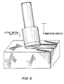
- the cutting process mechanism is as shown in FIG. 1. Cutting of a material, like rock, is carried out due to thrust force T and normal component C n of the cutting force, generated by an equipment drive. Under the action of these forces, the tool simultaneously moves in horizontal and vertical directions generating complicated stresses that overwhelm rock resistance.
- both forces C n and T generate a confined zone of superpressurized rock, located next to the bit cutting edge.
- This so-called kernal is an accumulator of energy which can discharge in an explosive way when accumulated energy exceeds ultimate rock resistance.
- the effective cutting bit must have an optimal combination of high cutting ability and high durability of the cutting element, reliable protection from overloading, preservation of the bit positive relief angle, and maintenance of other initial parameters throughout the lifetime of the cutting bit.
- the first group of rock-destructing tools is comprised of cutting bits with non-rotatable cutting elements.
- U.S. Patent 1,174,433 discloses a non-rotating cutter which has a convex front face. But it has a positive rake angle; the angle between its longitudinal axis and the cut (treated) surface behind a bit (defined as attack angle) is less than 90°. It has a short cutting edge, positive rake angle and small included angle. Compared to the present invention, this bit has low durability and wear resistance and it only can be used for destruction of the soft and not abrasive rock.
- U.S. Patents 4,538,691 and 4,678,237 disclose non-rotating cutting tools having rock-destructing elements with a flat front face and substantial negative rake angle, providing protection of the bit from overloading due to operation of a lifting force.
- the described bit has a low cutting ability and requires significant thrust force for penetration into rock. Its attack angle does not exceed 90°.
- U.S. Patent 4,538,690; 4,558,753 and 4,593,777 disclose non-rotating cutting bits, having a rock-destructing element with a concave front face, oriented at a large negative rake angle, which is used to increase bit durability (including protection against overload). However, this bit also has low cutting and penetration ability. The bit is oriented at an attack angle that is less than 90°.
- the second group of patented rock-destructing tools is comprised of round bits with symmetrical cutting elements, which can rotate around its own longitudinal axes.
- the bits' rock-destructing elements have a conical shape (direct cone) and destroy rock by their convex-shaped back faces, as disclosed, for example, in U.S. Patent 3,650,656; 3,807,804 and 4,804,231.
- Russian Patent 1,671,850-A1 discloses the same so-called conical bit type, which has limited contact area, dependent on attack angle, that can be changed from 0 to 90°. Described bits are of a crushing type that operate without generation of long destructive cracks. The bits are oriented at an attack angle which does not exceed 90°. They have convex front and back faces; zero or negative relief angle and positive rake angle. Their self-rotation is not reliable. Therefore they cannot self-sharpen. These bits have significantly higher specific energy requirements for rock destruction compared to the present invention.
- the second sub-group of the rotatable tools includes bits, which destroy rock by their front faces, as disclosed, for example, in U.S. Patent 5,078,219.
- This bit has a convex back face, positive relief angle and an attack angle close to zero.
- the bit is a cutting tool when its cutting edge is a sharp one.
- the bit design does not protect it against fast dulling. Bit self-sharpening is impossible since there is no correction of the bit's worn area. As discussed previously, a sizeable width of this contact area for normal force, T, greatly reduces cutting ability.
- the third sub-group of the rotatable tools is represented by chisel bits, as disclosed, for example, in German patents 3,336,154-A1 and 3,234,521-A1. These bits have a replaceable cutting sleeve of a tubular chisel shape with a sharpened front end.
- the bits have a rather small included angle, a sizeable positive rake angle and a small relief angle. Therefore, these bits have low durability and wear resistance and they can only be applied for destruction of soft, not abrasive rock.
- the bits have an attack angle much less than 90°, a front face which is concave, a back face which is convex, and the bit cannot self-sharpen.
- one feature of the present invention resides, briefly stated, in a method of cutting in accordance with which a cutting rotative bit is used with a body and a generally circular cutting element or multiple elements, connected with the body wherein the cutting element has a convex front face, and in the inventive method the cutting rotative bit is oriented so that an attack angle of the bit's cutting element exceeds 90°.
- Attack angle is the angle between the longitudinal axis of the bit and the cut surface behind the bit).
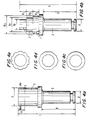
- a cutting tool in accordance with the present invention has a body which is identified with reference numeral 1 and a cutting element or an insert which is identified with reference numeral 2.
- the body is further provided with a tail part 3 which contributes to rotation of the bit about its longitudinal axis and can be used to hold the cutting tool.
- the tail part of the bit is arranged in a tool holder 4 and retained by a retainer 5.
- the tool holder or a plurality of tool holders are aligned with respect to each other and attached to a cutter support 6.
- the main angles, providing the spatial orientation of each cutting rotative bit, are determined by mounting of the tool holder to the cutter support as will be discussed hereinbelow.
- the tail portion 3 of the bit and therefore the cutting rotative bit are held in the tool holder rotatably around its longitudinal axis and fixed in the axial direction.
- the cylindrical or conical body is made, as a rule, from alloyed steel, which has a substantial elasticity and strength.
- the insert 2 (FIG. 3) is ring-shaped and can be formed as a solid ring or a composite ring, composed of individual segments.
- the inner opening of the ring can be cylindrical or conical while its surface, which is in contact with the body, may be flat or curved. In other embodiments of this invention, the entire bit can be exclusively made of one material.
- the upper surface of the insert can be flat, as shown in FIGS. 3a, 3b, 3c. It can also be concave, as shown in FIG. 3d or convex,, as shown in FIG. 3e.
- the outer surface of the ring which is the front face of the bit always has a convex shape formed by a generatrix of a cylinder, as shown in FIGS. 3a, 3d, and 3e, or direct cone, as shown in FIG. 3c or inverse cone, as shown in FIG. 3b.
- Outer contour of the cutting element can be straight one, as shown in FIG. 4a, or stepped one, as shown in FIG. 4b.
- Shape of the cutting element in cross-section can be round, as shown, in FIG. 4c, or polygonal, as shown in FIG. 4d, or daisy-shaped, as shown in FIG. 4e.
- the insert is made of hard wear resistant materials, preferably sintered hard alloys of the tungsten carbide group.
- the convex shape of the front face ofthe insert is preferable, since the cutting forces are directed toward the center of the ring and are resolved into mainly safe compressive stresses, instead of tensile stresses which are very dangerous for brittle materials like the hard alloys the insert is composed of.
- the convex shape of the front face of the bit also contributes to more efficient removal of the destroyed rock from the cutting zone due to dispersing of cuttings to both sides of the bit.
- connection of the insert to the body can be performed by brazing, in particular for the composite ring, with use of high temperature brazing filler metal, or performed with interference for press fit.
- the ring-shaped insert provides semi-closed containment of brazing materials to ensure durable and reliable joining of the body and insert which is particularly important in condition of dynamic loads.
- the press fitting on the other hand, eliminates residual thermal stresses which are characteristic of high temperature brazing due to different expansion coefficients of the joined elements.
- the solid bits which are not subdivided into the body and insert are recommended for cutting of non-abrasive materials. It must be subjected to a special thermal treatment, for example, isothermic quenching to provide different hardness of the body portion and cutting element portion of the bit.
- the main new feature of the present invention is that the inventive method is performed so that the cutting rotative bit is oriented to the surface of the rock to be cut at an attack angle ⁇ which exceeds 90°, a shown in FIGS. 2 and 5b.
- Skew angle ⁇ shown in FIGS. 5a and 5c is measured in the plane of the cut rock surface and is the angle between the projection of the bit longitudinal axis and the direction of bit motion.
- the tool attack angle ⁇ in combination with tool skew angle ⁇ provides favorable conditions for optimization of the main parameters of the tool (including a rake angle ⁇ and a relief angle ⁇ of the bit cutting edge).
- the rake angle ⁇ b has its maximum negative value. Moving from point B to the right or to the left increases this angle so as to assume its zero value at the point D and its positive value at the point E. Therefore, at the point E the thrust force per unit length will be maximal, when compared with remaining points of the cutting edge of the tool over the arc AE in FIG. 5c. Therefore, the intensity of friction and wear is maximum at E and, in combination with the zero value of the relief angle, provides conditions which are close to machine tool sharpening. With the introduction of the positive angle of correction ⁇ , FIG. 5b, the effect of self-sharpening is further increased.
- the negative rake angle of the tool which is maximal in central part of the cutting edge, contributes to the self-protection against overloading.
- a negative rake angle generates a lifting force which lifts the tool from the rock.
- Such overloading is usually caused by the increase of the hardness of the rock to be broken.
- the attack angle in accordance with the present invention can be within the range of 90° to 120°.
- the skew angle can be within the range of 5° to 40°.
- the rake angle can be within the range of plus 15° to minus 15°.
- the relief angle can be within the range from 0 to 20°.
- the included angle can be within the range of 50° to 100°.
Landscapes
- Engineering & Computer Science (AREA)
- Mining & Mineral Resources (AREA)
- Mechanical Engineering (AREA)
- Life Sciences & Earth Sciences (AREA)
- General Life Sciences & Earth Sciences (AREA)
- Geochemistry & Mineralogy (AREA)
- Geology (AREA)
- Earth Drilling (AREA)
- Processing Of Stones Or Stones Resemblance Materials (AREA)
- Milling Processes (AREA)
- Joining Of Corner Units Of Frames Or Wings (AREA)
- Crushing And Pulverization Processes (AREA)
- Excavating Of Shafts Or Tunnels (AREA)
- Cutting Tools, Boring Holders, And Turrets (AREA)
- Pressure Welding/Diffusion-Bonding (AREA)
- Sewing Machines And Sewing (AREA)
- Treatment Of Fiber Materials (AREA)
Abstract
Description
- Significant cutting ability of the bit, which provides highly efficient destruction of the rock and other similar material;
- Continuous, forced self-rotation of the bit around its own longitudinal axis, which provides increased bit cutting edge length and uniform wear along its back face;
- Continuous, forced self-sharpening of the bit, that maintains the initial positive relief angle, of the bit along its whole cutting edge by grinding away interfering cutting element material along its back face;
- Increased durability of the bit resulting in high bit reliability and longevity and increased range of working material that may be engaged because of highly rational force transmission through the cutting element of the bit. Stress in the brittle cutting element is almost entirely compressive;
- Effective operation of the bit until a large proportion of the cutting element is consumed by normal wear providing long bit service life.
- The front face of the bit is the convex surface of the insert, while the back face of the tool is the end surface of the insert;
- The rotation of the tool around its longitudinal axis (FIGS. 5b and 5c) occurs due to rolling of the bit cutting edge along the corresponding surface of the rock under the action of the rotary moment Mrot. Mrot is the couple of the frictional force generated by force Qrot (and thrust force) and tangential force Q.
- The direction of the rectilinear motion of the tool does not coincide with the direction of cutting (breaking) of the rock, which is different for each point of the cutting edge of the tool, as shown in FIG. 5c.
- Instantaneous values of rake angle ψi and a relief angle δi vary contiously from point to point along bit cutting edge (arc AE, FIG. 5c).
- Absence of substantial resistance to the rotation along the back face of the tool due to the positive relief angle; and
- Use of substantial cutting force C (as compared with the thrust force), which is produced by the drive of the cutting equipment to form the significant Qrot.
Claims (15)
- A cutting self-rotating and self-sharpening tool comprising a cutting element (2) rotatable about a longitudinal axis of the cutting element (2) and mounting means (4) for mounting said cutting element so that in use of the tool, when the latter is moved in a cutting direction over a surface to be cut to produce a cut surface, the cutting element is held at an attack angle which is defined as the angle between its longitudinal axis and the cut surface behind the tool, characterised in that said attack angle is at least 90° and in that the cutting element has a skew angle of at least 5°.
- A tool according to claim 1, characterised in that said cutting element (2) has a convex front face.
- A tool according to claim 2, characterised in that said convex front face has a cylindrical shape, a direct conical shape or an inverse conical shape.
- A tool according to any one of the preceding claims, characterised in that said cutting element has a back face with a convex shape, a concave shape, a flat shape or a combination of these shapes.
- A tool according to any one of the preceding claims, characterised in that said cutting element (2) has a longitudinal section with an outer shape which is straight or stepped.
- A tool according to claim 1, characterised in that said cutting element has a transverse section with an outer shape which is a round shape, a polygonal shape or a daisy shape.
- A tool according to any one of the preceding claims, characterised in that said attack angle is no more than 120°.
- A tool according to any one of the preceding claims, characterised in that the said skew angle is no more than 40°.
- A tool according to any one of the preceding claims, characterised in that said cutting element has a rake angle of between -15° and +15°.
- A tool according to any one of the preceding claims, characterised in that said cutting element has a relief angle of between 0° and 20°.
- A tool according to any one of the preceding claims, characterised in that said cutting element has an included angle of between 50° and 100°.
- A tool according to claim 11, characterised in that said relief angle has a positive angular correction, providing cutting element self-sharpening, determined from formula Δδ ≤ arc sin (sinα cosβ), where α is the skew angle, β is the attack angle.
- A method of cutting comprising mounting a cutting element (2) in mounting means (4) so that the cutting element is rotatable about a longitudinal axis of the latter and moving the tool in a cutting direction over a surface to be cut to produce a cut surface behind the tool, the cutting element during cutting having an attack angle defined as the angle between its longitudinal axis and the cut surface, characterised in that said attack angle is at least 90°, preferably no more than 120°, and in that the cutting element has a skew angle of at least 5°, most preferably between 10° and 40°.
- A method according to claim 13, characterised in that said mounting includes mounting the cutting element (2) so as to provide a rake angle of the latter of between -15° and +15°.
- A method according to claim 13 or 14, characterised in that said mounting includes mounting the cutting element (2) so as to provide a relief angle of the latter of between 0° and 20°.
Applications Claiming Priority (3)
| Application Number | Priority Date | Filing Date | Title |
|---|---|---|---|
| US394908 | 1995-02-27 | ||
| US08/394,908 US5520444A (en) | 1995-02-27 | 1995-02-27 | Method of cutting and cutting rotative bit |
| PCT/US1996/002707 WO1996027072A1 (en) | 1995-02-27 | 1996-02-26 | Method of cutting and cutting rotative bit |
Publications (3)
| Publication Number | Publication Date |
|---|---|
| EP0811112A1 EP0811112A1 (en) | 1997-12-10 |
| EP0811112A4 EP0811112A4 (en) | 1998-08-26 |
| EP0811112B1 true EP0811112B1 (en) | 2001-05-23 |
Family
ID=23560891
Family Applications (1)
| Application Number | Title | Priority Date | Filing Date |
|---|---|---|---|
| EP96908560A Expired - Lifetime EP0811112B1 (en) | 1995-02-27 | 1996-02-26 | Method of cutting and cutting rotative bit |
Country Status (12)
| Country | Link |
|---|---|
| US (1) | US5520444A (en) |
| EP (1) | EP0811112B1 (en) |
| JP (1) | JP3588362B2 (en) |
| KR (1) | KR100486312B1 (en) |
| CN (1) | CN1070986C (en) |
| AT (1) | ATE201480T1 (en) |
| AU (1) | AU714347B2 (en) |
| CA (1) | CA2214047C (en) |
| DE (1) | DE69612965T2 (en) |
| EA (1) | EA000101B1 (en) |
| ES (1) | ES2161353T3 (en) |
| WO (1) | WO1996027072A1 (en) |
Cited By (2)
| Publication number | Priority date | Publication date | Assignee | Title |
|---|---|---|---|---|
| US9303461B2 (en) | 2012-10-26 | 2016-04-05 | Baker Hughes Incorporated | Cutting elements having curved or annular configurations for earth-boring tools, earth-boring tools including such cutting elements, and related methods |
| US9388639B2 (en) | 2012-10-26 | 2016-07-12 | Baker Hughes Incorporated | Rotatable cutting elements and related earth-boring tools and methods |
Families Citing this family (14)
| Publication number | Priority date | Publication date | Assignee | Title |
|---|---|---|---|---|
| FR2735522B1 (en) * | 1995-06-16 | 1997-09-05 | Total Sa | MONOBLOCK DRILLING TOOL SIZE |
| US5823782A (en) * | 1995-12-29 | 1998-10-20 | Tinkers & Chance | Character recognition educational system |
| US5799741A (en) * | 1996-02-26 | 1998-09-01 | Champion Equipment Corp. | Method of cutting and a cutting rotative bit |
| US6375272B1 (en) * | 2000-03-24 | 2002-04-23 | Kennametal Inc. | Rotatable cutting tool insert |
| AU750553B2 (en) * | 2000-08-07 | 2002-07-18 | Albert Daniel Dawood | A coal and rock cutting picks |
| US7156006B2 (en) * | 2003-09-02 | 2007-01-02 | Kennametal Inc. | Method and assembly for rotating a cutting insert during a turning operation and inserts used therein |
| AU2007209768B2 (en) * | 2006-01-25 | 2012-08-23 | Rock Saw Holdings Pty Ltd | A holder for holding a tooth on a body of a cutting blade or grinding drum for cutting or grinding rock or hard earth formations |
| AU2007359121B2 (en) * | 2007-09-18 | 2015-05-07 | Caterpillar Global Mining Europe Gmbh | Roller drill or roller bit |
| SE534651C2 (en) * | 2010-02-12 | 2011-11-08 | Sandvik Intellectual Property | Cutting, tool part, procedure and machine tool for chip cutting metal machining |
| JP6710902B2 (en) * | 2015-06-18 | 2020-06-17 | 株式会社ジェイテクト | Cutting device, cutting method and annular tool |
| JP6565380B2 (en) * | 2015-06-30 | 2019-08-28 | 株式会社ジェイテクト | Cutting device, cutting method and annular tool |
| US11473273B2 (en) * | 2018-04-13 | 2022-10-18 | Caterpillar Inc. | Tool bit having a cylindrical profile and blade assembly |
| KR102117844B1 (en) * | 2018-09-06 | 2020-06-02 | 한국생산기술연구원 | Methods for continuous abrasion test of rock cutting tool, apparatus thereof and, storage media for storing a computer program therefor |
| KR102150328B1 (en) | 2019-11-18 | 2020-09-01 | 배연구 | Scent emission sock |
Family Cites Families (4)
| Publication number | Priority date | Publication date | Assignee | Title |
|---|---|---|---|---|
| DE3336154A1 (en) * | 1982-09-17 | 1985-04-25 | Ruhrkohle Ag, 4300 Essen | Round-shank pick |
| DE3234521C2 (en) * | 1982-09-17 | 1986-11-06 | Ruhrkohle Ag, 4300 Essen | Picks |
| SU1671850A1 (en) * | 1989-09-25 | 1991-08-23 | Институт горного дела им.А.А.Скочинского | Mining machine actuator |
| US5078219A (en) * | 1990-07-16 | 1992-01-07 | The United States Of America As Represented By The Secretary Of The Interior | Concave drag bit cutter device and method |
-
1995
- 1995-02-27 US US08/394,908 patent/US5520444A/en not_active Expired - Fee Related
-
1996
- 1996-02-26 CA CA002214047A patent/CA2214047C/en not_active Expired - Lifetime
- 1996-02-26 WO PCT/US1996/002707 patent/WO1996027072A1/en not_active Ceased
- 1996-02-26 KR KR1019970705943A patent/KR100486312B1/en not_active Expired - Lifetime
- 1996-02-26 DE DE69612965T patent/DE69612965T2/en not_active Expired - Lifetime
- 1996-02-26 JP JP52639496A patent/JP3588362B2/en not_active Expired - Lifetime
- 1996-02-26 EA EA199700128A patent/EA000101B1/en not_active IP Right Cessation
- 1996-02-26 AT AT96908560T patent/ATE201480T1/en active
- 1996-02-26 EP EP96908560A patent/EP0811112B1/en not_active Expired - Lifetime
- 1996-02-26 ES ES96908560T patent/ES2161353T3/en not_active Expired - Lifetime
- 1996-02-26 CN CN96192189A patent/CN1070986C/en not_active Expired - Fee Related
- 1996-02-26 AU AU51766/96A patent/AU714347B2/en not_active Expired
Cited By (4)
| Publication number | Priority date | Publication date | Assignee | Title |
|---|---|---|---|---|
| US9303461B2 (en) | 2012-10-26 | 2016-04-05 | Baker Hughes Incorporated | Cutting elements having curved or annular configurations for earth-boring tools, earth-boring tools including such cutting elements, and related methods |
| US9388639B2 (en) | 2012-10-26 | 2016-07-12 | Baker Hughes Incorporated | Rotatable cutting elements and related earth-boring tools and methods |
| US9828811B2 (en) | 2012-10-26 | 2017-11-28 | Baker Hughes, A Ge Company, Llc | Rotatable cutting elements and related earth-boring tools and methods |
| US10053917B2 (en) | 2012-10-26 | 2018-08-21 | Baker Hughes Incorporated | Rotatable cutting elements and related earth-boring tools and methods |
Also Published As
| Publication number | Publication date |
|---|---|
| AU5176696A (en) | 1996-09-18 |
| EA199700128A1 (en) | 1997-12-30 |
| EP0811112A4 (en) | 1998-08-26 |
| ATE201480T1 (en) | 2001-06-15 |
| US5520444A (en) | 1996-05-28 |
| CA2214047C (en) | 2006-03-28 |
| KR100486312B1 (en) | 2005-08-18 |
| EP0811112A1 (en) | 1997-12-10 |
| EA000101B1 (en) | 1998-08-27 |
| JP3588362B2 (en) | 2004-11-10 |
| CN1070986C (en) | 2001-09-12 |
| DE69612965D1 (en) | 2001-06-28 |
| KR19980702540A (en) | 1998-07-15 |
| ES2161353T3 (en) | 2001-12-01 |
| AU714347B2 (en) | 1999-12-23 |
| CN1176677A (en) | 1998-03-18 |
| CA2214047A1 (en) | 1996-09-06 |
| DE69612965T2 (en) | 2002-06-20 |
| WO1996027072A1 (en) | 1996-09-06 |
Similar Documents
| Publication | Publication Date | Title |
|---|---|---|
| EP0811112B1 (en) | Method of cutting and cutting rotative bit | |
| US7523794B2 (en) | Wear resistant assembly | |
| US9316061B2 (en) | High impact resistant degradation element | |
| US4339009A (en) | Button assembly for rotary rock cutters | |
| US5161627A (en) | Attack tool insert with polycrystalline diamond layer | |
| EP2049769B1 (en) | Thick pointed superhard material | |
| US20030230926A1 (en) | Rotating cutter bit assembly having hardfaced block and wear washer | |
| EP1330950B1 (en) | Stump grinding apparatus | |
| US20040026983A1 (en) | Monolithic point-attack bit | |
| JP4050985B2 (en) | Pick for cutting coal and bedrock | |
| US20040065484A1 (en) | Diamond tip point-attack bit | |
| US5799741A (en) | Method of cutting and a cutting rotative bit | |
| US9458607B2 (en) | Rotatable cutting tool with head portion having elongated projections | |
| GB2274129A (en) | Rotary cone rock bit with ultra hard heel row inserts | |
| JPH11509899A (en) | Rotating bit for cutting and its cutting method | |
| NZ206863A (en) | Mineral breaker | |
| US6607249B2 (en) | Conical bit penetrator pocket protector for earth displacement equipment | |
| US9476299B2 (en) | Mining and demolition tool | |
| AU2016312916A1 (en) | Asymmetric pick tool with an aspect ratio between leading and trailing edges | |
| AU2008271918A1 (en) | Cutting tip and tool | |
| CN106522940A (en) | Abrasion-resistant tool bit | |
| US12247486B2 (en) | Bolsters for degradation picks | |
| EP1230465A1 (en) | Multiple cutter rotary hammer bit | |
| CN110145239B (en) | Drilling inserts, roller cone bits and processing methods for drilling inserts | |
| US4783123A (en) | Tool bit for impact ripping of a mine face |
Legal Events
| Date | Code | Title | Description |
|---|---|---|---|
| PUAI | Public reference made under article 153(3) epc to a published international application that has entered the european phase |
Free format text: ORIGINAL CODE: 0009012 |
|
| 17P | Request for examination filed |
Effective date: 19970818 |
|
| AK | Designated contracting states |
Kind code of ref document: A1 Designated state(s): AT BE CH DE DK ES FR GB GR IE IT LI NL PT SE |
|
| A4 | Supplementary search report drawn up and despatched |
Effective date: 19980709 |
|
| AK | Designated contracting states |
Kind code of ref document: A4 Designated state(s): AT BE CH DE DK ES FR GB GR IE IT LI NL PT SE |
|
| 17Q | First examination report despatched |
Effective date: 19990503 |
|
| GRAG | Despatch of communication of intention to grant |
Free format text: ORIGINAL CODE: EPIDOS AGRA |
|
| GRAG | Despatch of communication of intention to grant |
Free format text: ORIGINAL CODE: EPIDOS AGRA |
|
| GRAH | Despatch of communication of intention to grant a patent |
Free format text: ORIGINAL CODE: EPIDOS IGRA |
|
| GRAH | Despatch of communication of intention to grant a patent |
Free format text: ORIGINAL CODE: EPIDOS IGRA |
|
| GRAA | (expected) grant |
Free format text: ORIGINAL CODE: 0009210 |
|
| AK | Designated contracting states |
Kind code of ref document: B1 Designated state(s): AT BE CH DE DK ES FR GB GR IE IT LI NL PT SE |
|
| PG25 | Lapsed in a contracting state [announced via postgrant information from national office to epo] |
Ref country code: NL Free format text: LAPSE BECAUSE OF FAILURE TO SUBMIT A TRANSLATION OF THE DESCRIPTION OR TO PAY THE FEE WITHIN THE PRESCRIBED TIME-LIMIT Effective date: 20010523 Ref country code: LI Free format text: LAPSE BECAUSE OF FAILURE TO SUBMIT A TRANSLATION OF THE DESCRIPTION OR TO PAY THE FEE WITHIN THE PRESCRIBED TIME-LIMIT Effective date: 20010523 Ref country code: CH Free format text: LAPSE BECAUSE OF FAILURE TO SUBMIT A TRANSLATION OF THE DESCRIPTION OR TO PAY THE FEE WITHIN THE PRESCRIBED TIME-LIMIT Effective date: 20010523 Ref country code: BE Free format text: LAPSE BECAUSE OF FAILURE TO SUBMIT A TRANSLATION OF THE DESCRIPTION OR TO PAY THE FEE WITHIN THE PRESCRIBED TIME-LIMIT Effective date: 20010523 |
|
| REF | Corresponds to: |
Ref document number: 201480 Country of ref document: AT Date of ref document: 20010615 Kind code of ref document: T |
|
| REG | Reference to a national code |
Ref country code: CH Ref legal event code: EP |
|
| REF | Corresponds to: |
Ref document number: 69612965 Country of ref document: DE Date of ref document: 20010628 |
|
| REG | Reference to a national code |
Ref country code: IE Ref legal event code: FG4D |
|
| ITF | It: translation for a ep patent filed | ||
| PG25 | Lapsed in a contracting state [announced via postgrant information from national office to epo] |
Ref country code: PT Free format text: LAPSE BECAUSE OF FAILURE TO SUBMIT A TRANSLATION OF THE DESCRIPTION OR TO PAY THE FEE WITHIN THE PRESCRIBED TIME-LIMIT Effective date: 20010823 Ref country code: DK Free format text: LAPSE BECAUSE OF FAILURE TO SUBMIT A TRANSLATION OF THE DESCRIPTION OR TO PAY THE FEE WITHIN THE PRESCRIBED TIME-LIMIT Effective date: 20010823 |
|
| PG25 | Lapsed in a contracting state [announced via postgrant information from national office to epo] |
Ref country code: GR Free format text: LAPSE BECAUSE OF FAILURE TO SUBMIT A TRANSLATION OF THE DESCRIPTION OR TO PAY THE FEE WITHIN THE PRESCRIBED TIME-LIMIT Effective date: 20010824 |
|
| NLV1 | Nl: lapsed or annulled due to failure to fulfill the requirements of art. 29p and 29m of the patents act | ||
| ET | Fr: translation filed | ||
| REG | Reference to a national code |
Ref country code: CH Ref legal event code: PL |
|
| REG | Reference to a national code |
Ref country code: ES Ref legal event code: FG2A Ref document number: 2161353 Country of ref document: ES Kind code of ref document: T3 |
|
| REG | Reference to a national code |
Ref country code: GB Ref legal event code: IF02 |
|
| PG25 | Lapsed in a contracting state [announced via postgrant information from national office to epo] |
Ref country code: IE Free format text: LAPSE BECAUSE OF NON-PAYMENT OF DUE FEES Effective date: 20020226 |
|
| PLBE | No opposition filed within time limit |
Free format text: ORIGINAL CODE: 0009261 |
|
| STAA | Information on the status of an ep patent application or granted ep patent |
Free format text: STATUS: NO OPPOSITION FILED WITHIN TIME LIMIT |
|
| 26N | No opposition filed | ||
| REG | Reference to a national code |
Ref country code: IE Ref legal event code: MM4A |
|
| PG25 | Lapsed in a contracting state [announced via postgrant information from national office to epo] |
Ref country code: IT Free format text: LAPSE BECAUSE OF NON-PAYMENT OF DUE FEES Effective date: 20100226 |
|
| PGRI | Patent reinstated in contracting state [announced from national office to epo] |
Ref country code: IT Effective date: 20110616 |
|
| REG | Reference to a national code |
Ref country code: FR Ref legal event code: PLFP Year of fee payment: 20 |
|
| PGFP | Annual fee paid to national office [announced via postgrant information from national office to epo] |
Ref country code: IT Payment date: 20150220 Year of fee payment: 20 Ref country code: ES Payment date: 20150326 Year of fee payment: 20 |
|
| PGFP | Annual fee paid to national office [announced via postgrant information from national office to epo] |
Ref country code: FR Payment date: 20150227 Year of fee payment: 20 Ref country code: SE Payment date: 20150227 Year of fee payment: 20 Ref country code: AT Payment date: 20150225 Year of fee payment: 20 Ref country code: GB Payment date: 20150226 Year of fee payment: 20 |
|
| PGFP | Annual fee paid to national office [announced via postgrant information from national office to epo] |
Ref country code: DE Payment date: 20150429 Year of fee payment: 20 |
|
| REG | Reference to a national code |
Ref country code: DE Ref legal event code: R071 Ref document number: 69612965 Country of ref document: DE |
|
| REG | Reference to a national code |
Ref country code: GB Ref legal event code: PE20 Expiry date: 20160225 |
|
| REG | Reference to a national code |
Ref country code: SE Ref legal event code: EUG |
|
| REG | Reference to a national code |
Ref country code: AT Ref legal event code: MK07 Ref document number: 201480 Country of ref document: AT Kind code of ref document: T Effective date: 20160226 |
|
| PG25 | Lapsed in a contracting state [announced via postgrant information from national office to epo] |
Ref country code: GB Free format text: LAPSE BECAUSE OF EXPIRATION OF PROTECTION Effective date: 20160225 |
|
| REG | Reference to a national code |
Ref country code: ES Ref legal event code: FD2A Effective date: 20160602 |
|
| PG25 | Lapsed in a contracting state [announced via postgrant information from national office to epo] |
Ref country code: ES Free format text: LAPSE BECAUSE OF EXPIRATION OF PROTECTION Effective date: 20160227 |