EP0810369A2 - Preignition detecting method - Google Patents
Preignition detecting method Download PDFInfo
- Publication number
- EP0810369A2 EP0810369A2 EP97108620A EP97108620A EP0810369A2 EP 0810369 A2 EP0810369 A2 EP 0810369A2 EP 97108620 A EP97108620 A EP 97108620A EP 97108620 A EP97108620 A EP 97108620A EP 0810369 A2 EP0810369 A2 EP 0810369A2
- Authority
- EP
- European Patent Office
- Prior art keywords
- preignition
- detecting
- fouling
- ignition
- command signal
- Prior art date
- Legal status (The legal status is an assumption and is not a legal conclusion. Google has not performed a legal analysis and makes no representation as to the accuracy of the status listed.)
- Granted
Links
- 238000000034 method Methods 0.000 title claims abstract description 21
- 230000002401 inhibitory effect Effects 0.000 claims description 21
- 230000007704 transition Effects 0.000 claims description 13
- 150000002500 ions Chemical class 0.000 description 16
- 238000002485 combustion reaction Methods 0.000 description 9
- 238000001514 detection method Methods 0.000 description 8
- 238000010586 diagram Methods 0.000 description 6
- 230000004044 response Effects 0.000 description 6
- 239000003990 capacitor Substances 0.000 description 5
- 239000000446 fuel Substances 0.000 description 5
- 239000000203 mixture Substances 0.000 description 5
- 239000000498 cooling water Substances 0.000 description 3
- 238000004804 winding Methods 0.000 description 3
- 239000003795 chemical substances by application Substances 0.000 description 1
- 230000006835 compression Effects 0.000 description 1
- 238000007906 compression Methods 0.000 description 1
- 230000006866 deterioration Effects 0.000 description 1
- 238000007599 discharging Methods 0.000 description 1
- 230000005764 inhibitory process Effects 0.000 description 1
- 238000009413 insulation Methods 0.000 description 1
- 239000000314 lubricant Substances 0.000 description 1
- 230000004048 modification Effects 0.000 description 1
- 238000012986 modification Methods 0.000 description 1
- 230000001105 regulatory effect Effects 0.000 description 1
Images


Classifications
-
- F—MECHANICAL ENGINEERING; LIGHTING; HEATING; WEAPONS; BLASTING
- F02—COMBUSTION ENGINES; HOT-GAS OR COMBUSTION-PRODUCT ENGINE PLANTS
- F02P—IGNITION, OTHER THAN COMPRESSION IGNITION, FOR INTERNAL-COMBUSTION ENGINES; TESTING OF IGNITION TIMING IN COMPRESSION-IGNITION ENGINES
- F02P17/00—Testing of ignition installations, e.g. in combination with adjusting; Testing of ignition timing in compression-ignition engines
- F02P17/12—Testing characteristics of the spark, ignition voltage or current
Definitions
- the present invention generally relates to a preignition detecting method, and, more particularly, to a preignition detecting method enabled to reliably detect preignition even when an ignition plug fouls.
- Preignition is defined as the phenomenon that an air-fuel mixture is spontaneously ignited during the compression stroke by residual heat contained in deposits which adhere to the ignition plug and/or an inner wall of an engine cylinder.
- Preignition causes not only a sharp decrease of the output of an engine and/or a fluctuation of the engine speed, but can also damage the engine at the worst.
- One such preignition detecting device is an ion current detecting device.
- the ion current detecting device detects a misfire based on the electric current generated when the electrical charge charged in a capacitor discharges through ions generated in air-fuel mixture if the mixture is normally ignited by sparking of the ignition plug.
- a preignition occurs, if an ion current is detected prior to ignition caused in response to an ignition command signal because ions are generated in an air-fuel mixture even when the preignition occurs (see the Japanese Unexamined Patent Publication (Kokai) No. 63-68774).
- Misjudgment that a preignition has occurred may be caused when an ignition plug fouls due to adhesion of a carbide of an additional agent contained in the fuel or lubricant, because a leakage current is generated when the ignition command signal is on due to deterioration of the insulation of the ignition plug.
- Figure 2(A) to 2(D) are diagrams for illustrating a problem to be solved by the present invention.
- the upper part of each of these four graphs represents the waveform of an ignition command signal.
- the lower part of each of these four graphs represents the waveform of a signal flowing through a secondary circuit.
- Figure 2(A) illustrates the case that an air-fuel mixture is normally ignited by discharging an ignition plug.
- impulses are generated in the secondary circuit in response to the leading edge and the falling edge of the ignition command signal, respectively. Thereafter, noises due to the discharge of the ignition plug are produced. Subsequently, an ion current is generated.
- Figure 2(B) illustrates a case where preignition occurs. As compared with FIG. 2(A), the width of a pulse generated in response to the falling edge of the ignition command signal becomes larger.
- Figure 2(C) illustrates a case where the ignition plug fouls.
- a leakage current flows through the secondary circuit in response to the leading edge of the ignition command signal.
- a leakage current flows therethrough.
- Figure 2(D) illustrates a case where the ignition plug fouls and preignition occurs.
- a pulse generated in response to the leading edge of the ignition command signal merges into another pulse generated in response to the falling edge of the ignition command signal. Consequently, a pulse caused by the preignition cannot be distinguished from the other pulse.
- the present invention is accomplished in view of the aforementioned problem of the prior art.
- an object of the present invention is to provide a preignition detecting method which can prevent preignition from being misjudged when an ignition plug fouls.
- a preignition detecting method which comprises the steps of: an ignition command signal output step for outputting an ignition command signal from an ignition device; a fouling detecting step for detecting fouling of an ignition plug in accordance with an ion current flowing between an ignition plug and the ground during a fouling detecting period in which an ignition command signal is being outputted at said ignition command signal output step; a preignition detecting step for detecting a preignition in accordance with the ion current flowing between the ignition plug and the ground during a preignition detecting period in which the ignition command signal is being outputted at said ignition command signal output step, later than said fouling detecting period; and a preignition detection inhibiting step for inhibiting said preignition detecting step from being performed, when it is determined that the ignition plug is fouling at said fouling detecting step.
- a preignition detecting method which further comprises a step of an inhibiting step for inhibiting said fouling detecting step from being performed until the preignition is not detected, at said preignition detecting step, once a preignition has been detected at said preignition detecting step.
- the detection of an ion current for detecting fouling is inhibited to prevent a misjudgment that the ignition plug fouls from being caused due to an advance of ignition timing once preignition has been detected.
- a preignition detecting method which comprises: an ignition command signal output step for outputting an ignition command signal from an ignition device; an integrating step for integrating an ion current, which flows between an ignition plug and the ground during a predetermined period in which an ignition command signal is being outputted at said ignition command signal output step; and the judgment step for judging that preignition has occurred, if an integrated value is not more than a predetermined fouling detecting threshold and is not less than a predetermined preignition detecting threshold smaller than the fouling detecting threshold.
- a preignition detecting method which further comprises: an operating-condition transition detecting step for detecting that a transition of the operating condition of an internal combustion engine to a specific operating condition, where preignitions often occur, from an operating condition other than the specific operating condition where preignitions rarely occur, has occurred; and a changing step for inhibiting said preignition detecting step from being performed, when it is determined that the ignition plug is fouling at said fouling detecting step after the transition of the operating condition is detected at said operating-condition transition detecting step, and for inhibiting said fouling detecting step from being performed, but removing the inhibition of said preignition detecting step after fouling has not once been detected.
- either one of said fouling detecting step and said preignition detecting step is performed after the transition of the operating condition of the internal combustion engine to the specific operating condition where preignitions often occur has been caused.
- FIG. 1 is a circuit diagram illustrating the configuration of an ion current detecting device for performing a preignition detecting method of the present invention.
- An ignition command signal is applied to an ignition coil 11 from an ignition device 10.
- the secondary winding of the ignition coil 11 has two terminals, one terminal is connected to an ignition plug 12 and the other is connected to the ground through the series of first and second Zener diodes 13, 14, cathode electrodes thereof being directly connected.
- a capacitor 15 is connected in parallel with the first Zener diode 13.
- a detecting resistor 16 is connected in parallel with the second Zener diode 14.
- a voltage developed across the detecting resistor 16 is supplied to a microcomputer 18 through an inverting amplifier 17.
- the ion current detecting circuit is driven by using the capacitor 15 as a power supply.
- FIG. 3 is a diagram of illustrating a preignition detecting method according to the present invention.
- Two voltages across the detecting resistor 16 are fetched into the microcomputer, one is a fouling detecting voltage V(t s ) fetched when a first fixed interval ts has elapsed after the pulse-like ignition command signal has been outputted, and the other is a preignition detecting voltage V(t p ) fetched when a second fixed interval tp longer than the first interval ts has elapsed.
- the fouling detecting voltage V(t s ) is higher than a predetermined fixed threshold voltage, the determination whether or not a preignition occurs is inhibited because a misjudgment may occur due to fouling.
- the fouling detecting voltage V(t s ) is lower than the predetermined threshold voltage, it is determined whether or not preignition occurs according to the preignition detection time voltage V(t p ) because a misjudgment never occurs due to fouling.
- the first predetermined time namely, a fouling detecting interval t s is set as a relatively short interval for the ignition command signal is outputted, for example, about 1 milliseconds (ms) after the ignition command signal rises.
- the second predetermined time namely, a preignition detecting period t p is set as a relatively long interval for the ignition command signal is outputted, for example, an interval until a time elapses to a moment corresponding to 5 degrees crank angle before the (pulse-like) ignition command signal falls.
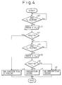
- FIG. 4 is a flowchart of a first preignition detecting routine executed by the microcomputer 18. This routine is executed every time an ignition command signal is outputted from the ignition device 10.
- the control waits until the fouling detecting interval t s has elapsed.
- step 42 it is determined whether the fouling detection voltage V(t s ) is higher than a predetermined fouling detecting threshold voltage V s .
- this routine is terminated after it is determined that the ignition plug fouls at step 43 without determining whether or not the preignition occurs to prevent the misjudgment from being caused.
- the control waits until the preignition detecting period has elapsed because a misjudgment never occurs if the ignition plug does not foul.
- the determination at step 44 is affirmative and data representing the preignition detecting voltage (t p ) is fetched into the microcomputer 18 at step 45.
- preignition detecting voltage V(t p ) is higher than a predetermined preignition detecting threshold voltage V p .
- the voltages are fetched twice while one ignition command signal is outputted.
- a preignition may not be detected, because an ignition timing gradually advances to a fouling detecting timing if an operation to avoid a preignition is not performed and the fouling detecting voltage V(t s ) becomes higher than the predetermined fouling detecting threshold voltage V s so that it is determined the ignition plug fouls though it does not actually foul.
- the fouling detecting timing becomes near to the ignition detecting time, a load for fetching voltages may become excessive high.
- a second preignition detecting routine shown in Figure 5 is to solve the problem described hereinabove and is executed every time an ignition command signal is outputted from the ignition control system 10.
- step 500 When the determination at step 500 is negative, namely, when it is not determined that preignition occurs, the control waits until the fouling detecting interval t s has elapsed.
- the determination at 503 is affirmative. Then, the fouling detecting voltage V(t s ) is fetched into the microcomputer 18 at step 503.
- step 503 it is determined whether the fouling detecting voltage V(t s ) is higher than a predetermined fouling detecting threshold voltage V s .
- this routine is terminated without determining whether or not preignition occurs, order to prevent a misjudgment from being caused.
- control waits at step 505 until the preignition detecting internal t p has elapsed.
- step 500 determines whether preignition occurs. If the determination at step 500 is affirmative, namely, when it is determined that preignition occurs, the control proceeds to step 505 without fetching fouling detecting voltage V s to reduce loads imposed on the microcomputer 18.
- the determination at step 505 is affirmative, and the preignition detecting voltage (t p ) is fetched into the microcomputer 18.
- the fouling detection voltage V(t s ) is higher than the predetermined fouling detecting threshold voltage V s , it is determined that the ignition plug fouls. Moreover, if the preignition detecting voltage V(t p ) is more than the predetermined preignition detecting threshold voltage V p , it is determined that preignition occurs. However, when noises are superposed on the voltage when fetching it, misjudgment may be caused.
- Third preignition detecting routine has been developed to solve the problem described hereinabove. This routine can eliminate the influence of noises by detecting a fouling and preignition according to the integrated value of a voltage developed across the detecting resistor 16, which is obtained by integrating the voltage when the ignition command signal is being outputted.
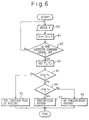
- the third preignition detecting routine shown in Figure 6 is executed every time an ignition command signal is outputted from the ignition device 10.
- the voltage developed across the detecting resistor 16 is fetched at step 60.
- step 62 it is determined whether or not the ignition command signal is off. When the determination is negative, namely, when the ignition command signal is on, the control returns to step 60.
- step 62 When the ignition command signal is off, the determination at step 62 is affirmative, and the control proceeds to step 63 where a fouling detecting value T s and a preignition detecting value T p are set.
- the fouling detecting value T s and the preignition detecting value T p may be determined as fixed values, or as functions of the engine speed or the temperature of cooling water.
- threshold values are defined as functions of the engine speed, the higher the engine speed becomes, the smaller these threshold values are set, because the higher the engine speed becomes, the smaller the integrated voltage becomes.
- threshold values are defined as functions of the temperature of cooling water, the lower the temperature of the cooling water becomes, the smaller the fouling detecting value T s is set, because the lower the temperature becomes, the more often the ignition plug fouls. Conversely the higher the temperature becomes, the smaller the preignition detecting value T p is set, because the higher the temperature becomes, the more often preignition occurs.
- step 64 it is determined whether or not the integrated value IS is larger than the fouling detecting value T s .
- the determination is affirmative , namely, when the integrated value IS is larger than the fouling detecting value T s , after it is determined that the ignition plug fouls at step 65, this routine is terminated.
- step 64 determines whether or not the integrated value IS is bigger than the fouling detecting value T s .
- step 66 When the determination at step 66 is affirmative, namely, when the integrated value IS is smaller than the fouling detecting value T s and is not smaller than the preignition detecting value T p , it is determined that preignition has occurred at step 67. Then, this routine is terminated.
- the voltages are twice read when the ignition command signal is being outputted, regardless of the operating condition of the internal combustion engine.
- the intervals between the times when the voltages are read become shorter, and the load required to the microcomputer 18 cannot be prevented from becoming high.
- a fourth preignition detecting routine has been developed to solve the problem described hereinabove.
- An object of the fourth preignition detecting routine is to reduce the load required to the microcomputer 18 by inhibiting the determination whether or not the ignition plug fouls when the operating condition of the internal combustion engine is transferred to the specific operating condition in which preignitions often occur.
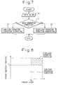
- Figure 7 is a flowchart of a fourth preignition detecting routine executed every time an ignition command signal is outputted.
- step 70 the engine speed N e of the engine and the intake manifold pressure PM are fetched into the microcomputer 18.
- Figure 8 is a graph for determining the operating condition of the internal combustion engine.
- the abscissa denotes the engine speed N e
- the ordinate denotes the intake manifold pressure PM when the engine speed N e is higher than a predetermined engine speed N H and the intake manifold pressure PM is higher than a predetermined pressure P H , the operating condition of the engine is determined as the high-load operating condition. Otherwise, the operating condition of the engine is determined as the low-load operating condition.
- step 71 If the determination at step 71 is negative, that is, if the internal combustion engine is in the low-load operating condition, this routine is terminated after the low-load operating condition subroutine is executed at step 72. Conversely, if the determination at step 71 is affirmative, that is, if the internal combustion engine is in the high-load operating condition, this routine is terminated after the high-load operating condition subroutine is executed at step 73.
- FIG. 9 is a flowchart of the low-load operating condition subroutine executed at step 72.
- the control waits until the fouling detecting time t s has elapsed.
- step 720 When the fouling detecting time t s has elapsed, the determination at step 720 is affirmative, and the control proceeds to step 721 where the fouling detecting voltage V(t s ) is fetched.
- step 722 it is determined whether the fouling detecting voltage V(t s ) is higher than the predetermined fouling detecting threshold voltage V s .
- step 722 When the determination at step 722 is affirmative, it is determined that the ignition plug is fouling and the fouling flag F s is set to "1" at step 723. Then, this routine is terminated after a counter CKUSU is reset at step 724.
- the preignition detecting voltage is not fetched because no preignition occurs in the low-load operating condition.
- FIG 10 is a flowchart of the high-load operating condition subroutine executed in step 73.
- step 730 it is determined whether or not the fouling flag F s is "1".
- FIG 11 is a flowchart of the non-fouling condition auxiliary routine executed in step 731.
- the control waits until the preignition detecting interval t p has elapsed.
- the determination at step 1a is affirmative, and the preignition detecting voltage V(t p ) is read at step 1b.
- step 1c it is determined whether or not the preignition detecting voltage V(t p ) is higher than the predetermined preignition detecting threshold voltage V p .
- step 1c When the determination at step 1c is negative, it is determined that no preignition occurs and execution of this auxiliary routine is terminated after a preignition flag is reset to "0".
- step 1c determines that preignition has occurred, and this auxiliary routine is terminated after the preignition flag F p is set to "1". Namely, when the ignition plug does not foul, the fouling detecting voltage is not fetched.
- FIG 12 is a flowchart of the non-fouling condition time auxiliary routine executed at step 732.
- the control waits until the fouling detecting interval t s has elapsed.
- the determination at step 2a is affirmative, and the control proceeds to step 2b where the fouling detecting voltage V(t s ) is fetched.
- step 2c it is determined whether or not the fouling detecting voltage V(t s ) is higher than the predetermined fouling detecting threshold voltage V s .
- step 2c When the determination at step 2c is affirmative, it is determined that the ignition plug is fouling. Then, this auxiliary routine is terminated after the counter CKUSU is reset to "0" at step 2d, and the fouling flag F s is set to "1" at step 2e.
- step 2c determines whether or not the ignition plug is not fouling.
- the counter CKUSU is incremented at step 2f, and it is determined whether or not the counter CKUSU is bigger than a predetermined value, for example, "3" at step 2g.
- step 2g When the determination at step 2g is affirmative, namely, when it is determined that the ignition plug has not been fouling while the counter CKUSU is incremented to "3" after the operating condition had been transferred to the high-load condition though the ignition plug fouled at the low-load condition, this auxiliary routine is terminated after the counter is reset at step 2h, and the fouling flag F s is reset to "0" at step 2j.
- step 2g When the determination at step 2g is negative, it is determined that the ignition plug is fouling even in the high-load operating condition and this auxiliary routine is terminated after the fouling flag F s is set to "1".
- the preignition detecting voltage is not fetched so as to avoid a misjudgment.
- a preignition detecting method which prevents preignition (PI) from being misjudged as having occurred when an ignition plug is fouling. It is determined whether or not the ignition plug fouls in accordance with a voltage, developed across a detecting resistor which is fetched into a microcomputer 18 at a relatively early timing after an ignition command signal is outputted from an ignition device. Further it is determined whether or not preignition occurs in accordance with another voltage fetched at a relatively late timing after the ignition command signal is outputted. When it is determined that the ignition plug is fouling, it is inhibited to fetch the another voltage at a relatively late timing to prevent a misjudgment that preignition occurs due to a leakage current from being caused though preignition does not actually occur.
Landscapes
- Engineering & Computer Science (AREA)
- Chemical & Material Sciences (AREA)
- Combustion & Propulsion (AREA)
- Mechanical Engineering (AREA)
- General Engineering & Computer Science (AREA)
- Ignition Installations For Internal Combustion Engines (AREA)
- Combined Controls Of Internal Combustion Engines (AREA)
- Other Investigation Or Analysis Of Materials By Electrical Means (AREA)
Abstract
Description
- The present invention generally relates to a preignition detecting method, and, more particularly, to a preignition detecting method enabled to reliably detect preignition even when an ignition plug fouls.
- Preignition is defined as the phenomenon that an air-fuel mixture is spontaneously ignited during the compression stroke by residual heat contained in deposits which adhere to the ignition plug and/or an inner wall of an engine cylinder.
- Preignition causes not only a sharp decrease of the output of an engine and/or a fluctuation of the engine speed, but can also damage the engine at the worst.
- Thus, hitherto, there have been proposed various kinds of preignition detecting devices. One such preignition detecting device is an ion current detecting device.
- Namely, the ion current detecting device detects a misfire based on the electric current generated when the electrical charge charged in a capacitor discharges through ions generated in air-fuel mixture if the mixture is normally ignited by sparking of the ignition plug. However, it has already been disclosed that it can be determined that a preignition occurs, if an ion current is detected prior to ignition caused in response to an ignition command signal because ions are generated in an air-fuel mixture even when the preignition occurs (see the Japanese Unexamined Patent Publication (Kokai) No. 63-68774).
- Misjudgment that a preignition has occurred may be caused when an ignition plug fouls due to adhesion of a carbide of an additional agent contained in the fuel or lubricant, because a leakage current is generated when the ignition command signal is on due to deterioration of the insulation of the ignition plug.
- Figure 2(A) to 2(D) are diagrams for illustrating a problem to be solved by the present invention. The upper part of each of these four graphs represents the waveform of an ignition command signal. The lower part of each of these four graphs represents the waveform of a signal flowing through a secondary circuit.
- Figure 2(A) illustrates the case that an air-fuel mixture is normally ignited by discharging an ignition plug. First, impulses are generated in the secondary circuit in response to the leading edge and the falling edge of the ignition command signal, respectively. Thereafter, noises due to the discharge of the ignition plug are produced. Subsequently, an ion current is generated.
- Figure 2(B) illustrates a case where preignition occurs. As compared with FIG. 2(A), the width of a pulse generated in response to the falling edge of the ignition command signal becomes larger.
- Figure 2(C) illustrates a case where the ignition plug fouls. A leakage current flows through the secondary circuit in response to the leading edge of the ignition command signal. In addition, even after the discharge of the ignition plug, a leakage current flows therethrough.
- Figure 2(D) illustrates a case where the ignition plug fouls and preignition occurs. A pulse generated in response to the leading edge of the ignition command signal merges into another pulse generated in response to the falling edge of the ignition command signal. Consequently, a pulse caused by the preignition cannot be distinguished from the other pulse.
- The present invention is accomplished in view of the aforementioned problem of the prior art.
- Accordingly, an object of the present invention is to provide a preignition detecting method which can prevent preignition from being misjudged when an ignition plug fouls.
- To achieve the foregoing object, according to one aspect of the present invention, there is provided a preignition detecting method which comprises the steps of: an ignition command signal output step for outputting an ignition command signal from an ignition device; a fouling detecting step for detecting fouling of an ignition plug in accordance with an ion current flowing between an ignition plug and the ground during a fouling detecting period in which an ignition command signal is being outputted at said ignition command signal output step; a preignition detecting step for detecting a preignition in accordance with the ion current flowing between the ignition plug and the ground during a preignition detecting period in which the ignition command signal is being outputted at said ignition command signal output step, later than said fouling detecting period; and a preignition detection inhibiting step for inhibiting said preignition detecting step from being performed, when it is determined that the ignition plug is fouling at said fouling detecting step.
- According to this method, when the ion current is detected at a relatively earlier time after the ignition command signal has been outputted, it is determined that the ignition plug is fouling and misjudgment that a preignition occur may be caused. Consequently, the detection of ion current for detecting preignition, which is performed at a relatively later time after the ignition command signal has been outputted, is inhibited.
- According to another aspect of the present invention, there is provided a preignition detecting method, which further comprises a step of an inhibiting step for inhibiting said fouling detecting step from being performed until the preignition is not detected, at said preignition detecting step, once a preignition has been detected at said preignition detecting step.
- According to the second method of the present invention, the detection of an ion current for detecting fouling is inhibited to prevent a misjudgment that the ignition plug fouls from being caused due to an advance of ignition timing once preignition has been detected.
- According to another aspect of the present invention, there is provided a preignition detecting method which comprises: an ignition command signal output step for outputting an ignition command signal from an ignition device; an integrating step for integrating an ion current, which flows between an ignition plug and the ground during a predetermined period in which an ignition command signal is being outputted at said ignition command signal output step; and the judgment step for judging that preignition has occurred, if an integrated value is not more than a predetermined fouling detecting threshold and is not less than a predetermined preignition detecting threshold smaller than the fouling detecting threshold.
- In the case of this method it is determined whether or not fouling and preignition have occurred according to the integrated value of the ion current detected when the ignition command signal is being outputted.
- According to a further aspect of the present invention, there is provided a preignition detecting method which further comprises: an operating-condition transition detecting step for detecting that a transition of the operating condition of an internal combustion engine to a specific operating condition, where preignitions often occur, from an operating condition other than the specific operating condition where preignitions rarely occur, has occurred; and a changing step for inhibiting said preignition detecting step from being performed, when it is determined that the ignition plug is fouling at said fouling detecting step after the transition of the operating condition is detected at said operating-condition transition detecting step, and for inhibiting said fouling detecting step from being performed, but removing the inhibition of said preignition detecting step after fouling has not once been detected.
- Thus, according to this method either one of said fouling detecting step and said preignition detecting step is performed after the transition of the operating condition of the internal combustion engine to the specific operating condition where preignitions often occur has been caused.
- Other features, objects and advantages of the present invention will become apparent from the following description of preferred embodiments with reference to the drawings in which like reference characters designate like or corresponding parts throughout several views, and in which:
- Figure 1 is a circuit diagram illustrating the configuration of an ion current detecting device;
- Figures 2(A) to 2(D) are diagrams for illustrating the problem to be solved by the present invention;
- Figure 3 is a diagram for illustrating a preignition detecting method;
- Figure 4 is a flowchart of a first preignition detecting routine;
- Figure 5 is a flowchart of a second preignition detecting routine;
- Figure 6 is a flowchart of a third preignition detecting routine;
- Figure 7 is a flowchart of a fourth preignition detecting routine;
- Figure 8 is a graph for determining an operating condition of an internal combustion engine;
- Figure 9 is a flowchart of a low-load operating condition subroutine;
- Figure 10 is a flowchart of a high-load operating condition subroutine;
- Figure 11 is a flowchart of an auxiliary routine for a non-fouling period; and
- Figure 12 is a flowchart of an auxiliary routine for a fouling period.
- Hereinafter, the preferred embodiments of the present invention will be described in detail by referring to the accompanying drawings.
- Figure 1 is a circuit diagram illustrating the configuration of an ion current detecting device for performing a preignition detecting method of the present invention. An ignition command signal is applied to an
ignition coil 11 from anignition device 10. - The secondary winding of the
ignition coil 11 has two terminals, one terminal is connected to anignition plug 12 and the other is connected to the ground through the series of first and second Zenerdiodes - Further, a
capacitor 15 is connected in parallel with the first Zenerdiode 13. A detectingresistor 16 is connected in parallel with the second Zenerdiode 14. - Furthermore, a voltage developed across the detecting
resistor 16 is supplied to amicrocomputer 18 through an invertingamplifier 17. - In this circuit, when a pulse-like ignition command signal is outputted from the
ignition device 10 to the primary winding of theignition coil 11, a high voltage induced in the secondary winding of theignition coil 11 at the falling edge of the ignition command signal causes theignition plug 12 to discharge. Simultaneously, thecapacitor 15 is charged with the voltage regulated by the first Zenerdiode 13. - Namely, after charging the
capacitor 15, the ion current detecting circuit is driven by using thecapacitor 15 as a power supply. - Figure 3 is a diagram of illustrating a preignition detecting method according to the present invention. Two voltages across the detecting
resistor 16 are fetched into the microcomputer, one is a fouling detecting voltage V(t s ) fetched when a first fixed interval ts has elapsed after the pulse-like ignition command signal has been outputted, and the other is a preignition detecting voltage V(tp) fetched when a second fixed interval tp longer than the first interval ts has elapsed. - If the fouling detecting voltage V(t s ) is higher than a predetermined fixed threshold voltage, the determination whether or not a preignition occurs is inhibited because a misjudgment may occur due to fouling.
- Conversely, if the fouling detecting voltage V(t s ) is lower than the predetermined threshold voltage, it is determined whether or not preignition occurs according to the preignition detection time voltage V(tp) because a misjudgment never occurs due to fouling.
- Note, the first predetermined time, namely, a fouling detecting interval t s is set as a relatively short interval for the ignition command signal is outputted, for example, about 1 milliseconds (ms) after the ignition command signal rises. And, the second predetermined time, namely, a preignition detecting period tp is set as a relatively long interval for the ignition command signal is outputted, for example, an interval until a time elapses to a moment corresponding to 5 degrees crank angle before the (pulse-like) ignition command signal falls.
- Figure 4 is a flowchart of a first preignition detecting routine executed by the
microcomputer 18. This routine is executed every time an ignition command signal is outputted from theignition device 10. - At
step 40, the control waits until the fouling detecting interval t s has elapsed. - When the fouling detecting interval t s has elapsed, the determination at step 41 is affirmative, and the fouling detecting voltage V(t s ) is fetched into the
microcomputer 18. - At step 42, it is determined whether the fouling detection voltage V(t s ) is higher than a predetermined fouling detecting threshold voltage V s . When the determination at step 42 is affirmative, this routine is terminated after it is determined that the ignition plug fouls at
step 43 without determining whether or not the preignition occurs to prevent the misjudgment from being caused. - When the determination at step 42 is negative, the control waits until the preignition detecting period has elapsed because a misjudgment never occurs if the ignition plug does not foul.
- When the preignition detecting interval tp has elapsed, the determination at step 44 is affirmative and data representing the preignition detecting voltage (tp) is fetched into the
microcomputer 18 atstep 45. - It is determined whether the preignition detecting voltage V(tp) is higher than a predetermined preignition detecting threshold voltage Vp. When the determination at
step 46 is affirmative, that is, when the preignition detecting voltage V(tp) is higher than the predetermined preignition detecting threshold voltage Vp, it is determined that preignition has occurred atstep 47. Then, this routine is terminated. - Conversely, when the determination at
step 46 is negative, that is, when the preignition detecting voltage V(tp) is lower than the predetermined preignition detecting threshold voltage Vp, this routine is terminated after it is determined that preignition has occurred atstep 47. - In the first preignition detecting routine, the voltages are fetched twice while one ignition command signal is outputted. However, if a preignition has once occurred, a preignition may not be detected, because an ignition timing gradually advances to a fouling detecting timing if an operation to avoid a preignition is not performed and the fouling detecting voltage V(t s ) becomes higher than the predetermined fouling detecting threshold voltage V s so that it is determined the ignition plug fouls though it does not actually foul. Further, when the fouling detecting timing becomes near to the ignition detecting time, a load for fetching voltages may become excessive high.
- A second preignition detecting routine shown in Figure 5 is to solve the problem described hereinabove and is executed every time an ignition command signal is outputted from the
ignition control system 10. - It is determined whether or not a preignition flag Fp is set to "1".
- When the determination at
step 500 is negative, namely, when it is not determined that preignition occurs, the control waits until the fouling detecting interval t s has elapsed. - When the fouling detecting interval t s has elapsed, the determination at 503 is affirmative. Then, the fouling detecting voltage V(t s ) is fetched into the
microcomputer 18 atstep 503. - At
step 503, it is determined whether the fouling detecting voltage V(t s ) is higher than a predetermined fouling detecting threshold voltage V s . When the determination atstep 503 is affirmative, it is determined that the ignition plug 12 fouls atstep 504. Then, this routine is terminated without determining whether or not preignition occurs, order to prevent a misjudgment from being caused. - Conversely, when the determination at
step 503 is negative, the control waits atstep 505 until the preignition detecting internal tp has elapsed. - Note, when the determination at
step 500 is affirmative, namely, when it is determined that preignition occurs, the control proceeds to step 505 without fetching fouling detecting voltage V s to reduce loads imposed on themicrocomputer 18. - When the preignition detecting interval tp has elapsed, the determination at
step 505 is affirmative, and the preignition detecting voltage (tp) is fetched into themicrocomputer 18. - It is determined whether the preignition detecting voltage V(tp) is higher than the predetermined preignition detecting threshold voltage Vp. When the determination at
step 507 is affirmative, that is, when the preignition detecting voltage V(tp) is higher than the predetermined preignition detecting threshold voltage Vp, after it is determined that preignition has occurred atstep 508 and the preignition occurrence flag is set to "1" atstep 509, this routine is terminated. - Conversely, when the determination at
step 507 is negative, that is, when the preignition detecting voltage V(tp) is lower than the predetermined preignition detecting threshold voltage Vp, after it is determined that no preignition occurs atstep 510, and the preignition flag is reset to "0", this routine is terminated. - In the first preignition detecting routine, if the fouling detection voltage V(t s ) is higher than the predetermined fouling detecting threshold voltage V s , it is determined that the ignition plug fouls. Moreover, if the preignition detecting voltage V(tp) is more than the predetermined preignition detecting threshold voltage Vp, it is determined that preignition occurs. However, when noises are superposed on the voltage when fetching it, misjudgment may be caused.
- Third preignition detecting routine has been developed to solve the problem described hereinabove. This routine can eliminate the influence of noises by detecting a fouling and preignition according to the integrated value of a voltage developed across the detecting
resistor 16, which is obtained by integrating the voltage when the ignition command signal is being outputted. - The third preignition detecting routine shown in Figure 6 is executed every time an ignition command signal is outputted from the
ignition device 10. The voltage developed across the detectingresistor 16 is fetched atstep 60. - Then, the integrated value IS of the voltage V is obtained by using the following equation at
step 61.
- At
step 62, it is determined whether or not the ignition command signal is off. When the determination is negative, namely, when the ignition command signal is on, the control returns to step 60. - When the ignition command signal is off, the determination at
step 62 is affirmative, and the control proceeds to step 63 where a fouling detecting value T s and a preignition detecting value Tp are set. - Note, when the ignition plug fouls, a leakage current flows throughout a period when an ignition command signal is outputted, whereas when preignition occurs, a current flows only for a latter half of the period when an ignition command signal is outputted. Thus, the fouling detection value T s becomes larger than the preignition detection value Tp.
- Note, the fouling detecting value T s and the preignition detecting value Tp may be determined as fixed values, or as functions of the engine speed or the temperature of cooling water.
- When threshold values are defined as functions of the engine speed, the higher the engine speed becomes, the smaller these threshold values are set, because the higher the engine speed becomes, the smaller the integrated voltage becomes.
- When threshold values are defined as functions of the temperature of cooling water, the lower the temperature of the cooling water becomes, the smaller the fouling detecting value T s is set, because the lower the temperature becomes, the more often the ignition plug fouls. Conversely the higher the temperature becomes, the smaller the preignition detecting value Tp is set, because the higher the temperature becomes, the more often preignition occurs.
- At
step 64, it is determined whether or not the integrated value IS is larger than the fouling detecting value T s . When the determination is affirmative , namely, when the integrated value IS is larger than the fouling detecting value T s , after it is determined that the ignition plug fouls atstep 65, this routine is terminated. - Conversely, when the determination at
step 64 is negative, namely, when the integrated value IS is smaller than the fouling detecting value T s , the control proceeds to step 66 where it is determined whether or not the integrated value IS is bigger than the preignition detecting value Tp. - When the determination at
step 66 is affirmative, namely, when the integrated value IS is smaller than the fouling detecting value T s and is not smaller than the preignition detecting value Tp, it is determined that preignition has occurred atstep 67. Then, this routine is terminated. - When the determination at
step 66 is negative namely, when the integrated value IS is smaller than the preignition detecting value Tp, it is determined that the condition is normal atstep 68. Then, this routine is terminated. - In the first preignition detecting routine, the voltages are twice read when the ignition command signal is being outputted, regardless of the operating condition of the internal combustion engine. Thus, when the engine speed becomes high, the intervals between the times when the voltages are read, become shorter, and the load required to the
microcomputer 18 cannot be prevented from becoming high. - A fourth preignition detecting routine has been developed to solve the problem described hereinabove. An object of the fourth preignition detecting routine is to reduce the load required to the
microcomputer 18 by inhibiting the determination whether or not the ignition plug fouls when the operating condition of the internal combustion engine is transferred to the specific operating condition in which preignitions often occur. - Figure 7 is a flowchart of a fourth preignition detecting routine executed every time an ignition command signal is outputted.
- At
step 70, the engine speed Ne of the engine and the intake manifold pressure PM are fetched into themicrocomputer 18. Atstep 71, it is determined whether or not the operating condition of the internal combustion engine is a high-load operating condition. - Figure 8 is a graph for determining the operating condition of the internal combustion engine. In this graph, the abscissa denotes the engine speed Ne, and the ordinate denotes the intake manifold pressure PM when the engine speed Ne is higher than a predetermined engine speed NH and the intake manifold pressure PM is higher than a predetermined pressure PH, the operating condition of the engine is determined as the high-load operating condition. Otherwise, the operating condition of the engine is determined as the low-load operating condition.
- If the determination at
step 71 is negative, that is, if the internal combustion engine is in the low-load operating condition, this routine is terminated after the low-load operating condition subroutine is executed atstep 72. Conversely, if the determination atstep 71 is affirmative, that is, if the internal combustion engine is in the high-load operating condition, this routine is terminated after the high-load operating condition subroutine is executed atstep 73. - Figure 9 is a flowchart of the low-load operating condition subroutine executed at
step 72. Atstep 720, the control waits until the fouling detecting time t s has elapsed. - When the fouling detecting time t s has elapsed, the determination at
step 720 is affirmative, and the control proceeds to step 721 where the fouling detecting voltage V(t s ) is fetched. - At
step 722, it is determined whether the fouling detecting voltage V(t s ) is higher than the predetermined fouling detecting threshold voltage V s . - When the determination at
step 722 is affirmative, it is determined that the ignition plug is fouling and the fouling flag F s is set to "1" atstep 723. Then, this routine is terminated after a counter CKUSU is reset atstep 724. - Conversely, when the determination at
step 722 is negative, it is determined that the ignition plug is not fouling. Then, this routine is terminated after the fouling flag F s is reset to "0" atstep 725. - Note, in the low-load operating condition subroutine, the preignition detecting voltage is not fetched because no preignition occurs in the low-load operating condition.
- Figure 10 is a flowchart of the high-load operating condition subroutine executed in
step 73. Atstep 730, it is determined whether or not the fouling flag F s is "1". - When the determination at
step 730 is negative, that is, when the fouling flag F s is not "1", the execution of this program is terminated after a non-fouling condition auxiliary routine is executed atstep 731. - When the determination at
step 730 is affirmative, that is, if the fouling flag F s is "1", this program is terminated after a fouling condition auxiliary routine is executed instep 732. - Figure 11 is a flowchart of the non-fouling condition auxiliary routine executed in
step 731. Atstep 1a, the control waits until the preignition detecting interval tp has elapsed. When the preignition detecting interval tp has elapsed, the determination atstep 1a is affirmative, and the preignition detecting voltage V(tp) is read atstep 1b. - At step 1c, it is determined whether or not the preignition detecting voltage V(tp) is higher than the predetermined preignition detecting threshold voltage Vp.
- When the determination at step 1c is negative, it is determined that no preignition occurs and execution of this auxiliary routine is terminated after a preignition flag is reset to "0".
- Conversely, when the determination at step 1c is affirmative, it is determined that preignition has occurred, and this auxiliary routine is terminated after the preignition flag Fp is set to "1". Namely, when the ignition plug does not foul, the fouling detecting voltage is not fetched.
- Figure 12 is a flowchart of the non-fouling condition time auxiliary routine executed at
step 732. Atstep 2a, the control waits until the fouling detecting interval t s has elapsed. When the fouling detecting interval t s has elapsed, the determination atstep 2a is affirmative, and the control proceeds to step 2b where the fouling detecting voltage V(t s ) is fetched. - At
step 2c, it is determined whether or not the fouling detecting voltage V(t s ) is higher than the predetermined fouling detecting threshold voltage V s . - When the determination at
step 2c is affirmative, it is determined that the ignition plug is fouling. Then, this auxiliary routine is terminated after the counter CKUSU is reset to "0" atstep 2d, and the fouling flag F s is set to "1" atstep 2e. - Conversely, if the determination at
step 2c is negative, it is determined that the ignition plug is not fouling. Then, the counter CKUSU is incremented atstep 2f, and it is determined whether or not the counter CKUSU is bigger than a predetermined value, for example, "3" atstep 2g. - When the determination at
step 2g is affirmative, namely, when it is determined that the ignition plug has not been fouling while the counter CKUSU is incremented to "3" after the operating condition had been transferred to the high-load condition though the ignition plug fouled at the low-load condition, this auxiliary routine is terminated after the counter is reset atstep 2h, and the fouling flag F s is reset to "0" atstep 2j. - When the determination at
step 2g is negative, it is determined that the ignition plug is fouling even in the high-load operating condition and this auxiliary routine is terminated after the fouling flag F s is set to "1". - Note, when the ignition plug is fouling, the preignition detecting voltage is not fetched so as to avoid a misjudgment.
- Although the preferred embodiments of the present invention have been described above, it should be understood that the present invention is not limited thereto and that other modifications will be apparent to those skilled in the art without departing from the spirit of the invention.
- The scope of the present invention, therefore, should be determined solely by the appended claims.
- A preignition detecting method which prevents preignition (PI) from being misjudged as having occurred when an ignition plug is fouling. It is determined whether or not the ignition plug fouls in accordance with a voltage, developed across a detecting resistor which is fetched into a
microcomputer 18 at a relatively early timing after an ignition command signal is outputted from an ignition device. Further it is determined whether or not preignition occurs in accordance with another voltage fetched at a relatively late timing after the ignition command signal is outputted. When it is determined that the ignition plug is fouling, it is inhibited to fetch the another voltage at a relatively late timing to prevent a misjudgment that preignition occurs due to a leakage current from being caused though preignition does not actually occur.
Claims (8)
- A preignition detecting device comprising:an ignition command signal outputting means for outputting an ignition command signal;a fouling detecting means for detecting fouling of an ignition plug in accordance with a current which flows from the ignition plug to a ground during a fouling detecting interval contained in a period when the ignition command signal is being outputted by said ignition command signal;a preignition detecting means for detecting a preignition in accordance with a current which flows from the ignition plug to a ground when a preignition detecting interval later than the fouling detecting interval contained in a period during the ignition command signal is being outputted by said ignition command signal; anda preignition detecting inhibiting means for inhibiting a preignition from being detected when fouling of the ignition plug is detected by said fouling detecting means.
- A preignition detecting device of claim 1, further comprising:a fouling detecting inhibiting means for inhibiting a fouling from being detected after a preignition has once been detected by said preignition detecting means until a preignition is not detected by said preignition detecting means.
- A preignition detecting device of claim 1, further comprising:an operating condition transition detecting means for detecting an operation condition transition from an operation condition except a specific operation condition where preignition often occurs in the specific operating condition; anda means for inhibiting preignition from being detected by said preignition detecting means when fouling of the ignition plug is being detected by said fouling detecting means, and for inhibiting fouling of the ignition plug from being detected by said fouling detecting means and removing inhibiting for a preignition detecting after fouling of the ignition plug has not been detected, after a operation condition transition was detected by said operating condition transition detecting means.
- A preignition detecting device comprising:an ignition command signal outputting means for outputting an ignition command signal;an integrating means for integrating a current which flows from an ignition plug to the ground during a predetermined fixed interval contained in a period when the ignition command signal is being outputted by said ignition command signal outputting means; anda determining means for determining that preignition occurs when an integrated value integrated by said integrating means is smaller than a predetermined fixed fouling threshold level and is bigger than a predetermined fixed preignition threshold level which is smaller than the predetermined fixed fouling threshold level.
- A preignition detecting method comprising the steps of:an ignition command signal outputting step for outputting an ignition command signal from an ignition device;a fouling detecting step for detecting fouling of an ignition plug in accordance with a current which flows from the ignition plug to a ground during a fouling detecting interval contained in a period when the ignition command signal is being outputted by said ignition command signal;a preignition detecting step for detecting preignition in accordance with a current which flows from the ignition plug to a ground during a preignition detecting interval later than the fouling detecting interval contained in a period when the ignition command signal is being outputted by said ignition command signal; anda preignition detecting inhibiting step for inhibiting a preignition from being detected when a fouling of the ignition plug is detected at said fouling detecting step.
- A preignition detecting method of claim 5, further comprising a step of:a fouling detecting inhibiting step for inhibiting fouling from being detected after a preignition has been detected at said preignition detecting step until preignition is not detected at said preignition detecting step.
- A preignition detecting method of claim 5, further comprising steps of:an operating condition transition detecting step for detecting an operation condition transition from an operation condition except a specific operation condition where preignition often occurs in the specific operating condition; anda step for inhibiting preignition from being detected at said preignition detecting step when fouling of the ignition plug is being detected at said fouling detecting step, and for inhibiting fouling of the ignition plug from being detected at said fouling detecting step and removing inhibiting for preignition detecting after a fouling of the ignition plug has not been detected, after a operation condition transition was detected at said operating condition transition detecting step.
- A preignition detecting method comprising steps of:an ignition command signal outputting step for outputting an ignition command signal from an ignition device;an integrating step for integrating a current which flows from an ignition plug to the ground during a predetermined fixed interval contained in a period during the ignition command signal is being outputted by said ignition device; anda determining step for determining that preignition occurs when an integrated value integrated at said integrating step is smaller than a predetermined fixed fouling threshold level and is bigger than a predetermined fixed preignition threshold level which is smaller than the predetermined fixed fouling threshold level.
Applications Claiming Priority (3)
| Application Number | Priority Date | Filing Date | Title |
|---|---|---|---|
| JP13692396A JP3176291B2 (en) | 1996-05-30 | 1996-05-30 | Pre-ignition detection method |
| JP13692396 | 1996-05-30 | ||
| JP136923/96 | 1996-05-30 |
Publications (3)
| Publication Number | Publication Date |
|---|---|
| EP0810369A2 true EP0810369A2 (en) | 1997-12-03 |
| EP0810369A3 EP0810369A3 (en) | 2000-03-01 |
| EP0810369B1 EP0810369B1 (en) | 2003-04-16 |
Family
ID=15186741
Family Applications (1)
| Application Number | Title | Priority Date | Filing Date |
|---|---|---|---|
| EP97108620A Expired - Lifetime EP0810369B1 (en) | 1996-05-30 | 1997-05-28 | Preignition detecting method |
Country Status (5)
| Country | Link |
|---|---|
| US (1) | US5751147A (en) |
| EP (1) | EP0810369B1 (en) |
| JP (1) | JP3176291B2 (en) |
| DE (1) | DE69720853T2 (en) |
| ES (1) | ES2191791T3 (en) |
Cited By (3)
| Publication number | Priority date | Publication date | Assignee | Title |
|---|---|---|---|---|
| EP0961029A1 (en) * | 1998-05-29 | 1999-12-01 | Renault | Control process for motor according to the degree of fouling of the spark plugs, and device therefor |
| EP1138940A2 (en) * | 2000-03-29 | 2001-10-04 | Ngk Spark Plug Co., Ltd. | Control system for an internal combustion engine and method carried out by the same |
| IT201900013755A1 (en) * | 2019-08-01 | 2021-02-01 | Eldor Corp Spa | METHOD OF MONITORING A SOILING CONDITION OF A SPARK PLUG FOR A COMBUSTION ENGINE, METHOD AND SYSTEM OF CONTROL OF AN IGNITION COIL IN AN INTERNAL COMBUSTION ENGINE |
Families Citing this family (19)
| Publication number | Priority date | Publication date | Assignee | Title |
|---|---|---|---|---|
| JP3783823B2 (en) * | 1999-09-03 | 2006-06-07 | 三菱電機株式会社 | Knock control device for internal combustion engine |
| JP3696002B2 (en) * | 1999-09-20 | 2005-09-14 | 三菱電機株式会社 | Knock control device for internal combustion engine |
| JP2003021034A (en) * | 2001-07-03 | 2003-01-24 | Honda Motor Co Ltd | Combustion state discriminating device for internal combustion engine |
| US6883497B2 (en) * | 2003-09-17 | 2005-04-26 | General Motors Corporation | Method of preventing preignition for an internal combustion engine |
| JP2008031981A (en) * | 2006-07-06 | 2008-02-14 | Denso Corp | Abnormality detection device for internal combustion engine |
| JP4431168B2 (en) * | 2007-10-30 | 2010-03-10 | 三菱電機株式会社 | Combustion state detection apparatus and combustion state detection method for internal combustion engine |
| JP4445020B2 (en) | 2008-01-09 | 2010-04-07 | 三菱電機株式会社 | Combustion state detection device and combustion state detection method for internal combustion engine |
| JP4906884B2 (en) * | 2009-04-09 | 2012-03-28 | 三菱電機株式会社 | Combustion state detection device for internal combustion engine |
| DE102010003305B4 (en) * | 2010-03-25 | 2022-05-25 | Bayerische Motoren Werke Aktiengesellschaft | Prevention of irregular combustion in an internal combustion engine |
| US20120029789A1 (en) * | 2010-04-30 | 2012-02-02 | Southwest Research Institute | Methods of detecting pre-ignition and preventing it from causing knock in direct injection spark ignition engines |
| US9127604B2 (en) | 2011-08-23 | 2015-09-08 | Richard Stephen Davis | Control system and method for preventing stochastic pre-ignition in an engine |
| US9097196B2 (en) * | 2011-08-31 | 2015-08-04 | GM Global Technology Operations LLC | Stochastic pre-ignition detection systems and methods |
| US8776737B2 (en) | 2012-01-06 | 2014-07-15 | GM Global Technology Operations LLC | Spark ignition to homogenous charge compression ignition transition control systems and methods |
| JP5561283B2 (en) * | 2012-01-11 | 2014-07-30 | 株式会社デンソー | Sensor signal processing device |
| US9080509B2 (en) * | 2012-02-10 | 2015-07-14 | Ford Global Technologies, Llc | System and method for monitoring an ignition system |
| US9121362B2 (en) | 2012-08-21 | 2015-09-01 | Brian E. Betz | Valvetrain fault indication systems and methods using knock sensing |
| US9133775B2 (en) | 2012-08-21 | 2015-09-15 | Brian E. Betz | Valvetrain fault indication systems and methods using engine misfire |
| US8973429B2 (en) | 2013-02-25 | 2015-03-10 | GM Global Technology Operations LLC | System and method for detecting stochastic pre-ignition |
| US9777697B2 (en) * | 2013-12-19 | 2017-10-03 | Ford Global Technologies, Llc | Spark plug fouling detection for ignition system |
Citations (6)
| Publication number | Priority date | Publication date | Assignee | Title |
|---|---|---|---|---|
| US4349782A (en) * | 1980-11-21 | 1982-09-14 | Doss James D | Shielded differentiator for automotive ignition applications |
| JPS61169669A (en) * | 1985-01-22 | 1986-07-31 | Nissan Motor Co Ltd | Device for detecting weak ignition of spark plug |
| JPS6368774A (en) * | 1986-09-09 | 1988-03-28 | Nippon Denso Co Ltd | Spark plug preignition detector for internal combustion engine |
| US4846129A (en) * | 1988-02-09 | 1989-07-11 | Chrysler Motors Corporation | Ignition system improvements for internal combustion engines |
| JPH04259671A (en) * | 1991-02-13 | 1992-09-16 | Mitsubishi Electric Corp | Ion current sensing device |
| US5204630A (en) * | 1991-06-26 | 1993-04-20 | Allied Signal Inc. | Preignition warning device |
Family Cites Families (6)
| Publication number | Priority date | Publication date | Assignee | Title |
|---|---|---|---|---|
| IT1093349B (en) * | 1978-03-03 | 1985-07-19 | Alfa Romeo Spa | DEVICE FOR THE PRE-IGNITION RELIEF IN AN INTERNAL COMBUSTION ENGINE |
| CA1331778C (en) * | 1988-07-01 | 1994-08-30 | Hideaki Arai | Abnormal combustion-detecting device and combustion control device for internal combustion engines |
| JP2721604B2 (en) * | 1991-09-30 | 1998-03-04 | 株式会社日立製作所 | Combustion condition diagnostic device |
| JPH05223002A (en) * | 1992-02-17 | 1993-08-31 | Hitachi Ltd | Misfire detecting device for internal combustion engine |
| JPH08165977A (en) * | 1994-12-12 | 1996-06-25 | Ngk Spark Plug Co Ltd | Method and device for evaluating heat resistance for ignition plug |
| JP3082634B2 (en) * | 1995-03-23 | 2000-08-28 | トヨタ自動車株式会社 | Preignition detection device |
-
1996
- 1996-05-30 JP JP13692396A patent/JP3176291B2/en not_active Expired - Fee Related
-
1997
- 1997-05-28 ES ES97108620T patent/ES2191791T3/en not_active Expired - Lifetime
- 1997-05-28 DE DE69720853T patent/DE69720853T2/en not_active Expired - Fee Related
- 1997-05-28 EP EP97108620A patent/EP0810369B1/en not_active Expired - Lifetime
- 1997-05-28 US US08/864,627 patent/US5751147A/en not_active Expired - Fee Related
Patent Citations (6)
| Publication number | Priority date | Publication date | Assignee | Title |
|---|---|---|---|---|
| US4349782A (en) * | 1980-11-21 | 1982-09-14 | Doss James D | Shielded differentiator for automotive ignition applications |
| JPS61169669A (en) * | 1985-01-22 | 1986-07-31 | Nissan Motor Co Ltd | Device for detecting weak ignition of spark plug |
| JPS6368774A (en) * | 1986-09-09 | 1988-03-28 | Nippon Denso Co Ltd | Spark plug preignition detector for internal combustion engine |
| US4846129A (en) * | 1988-02-09 | 1989-07-11 | Chrysler Motors Corporation | Ignition system improvements for internal combustion engines |
| JPH04259671A (en) * | 1991-02-13 | 1992-09-16 | Mitsubishi Electric Corp | Ion current sensing device |
| US5204630A (en) * | 1991-06-26 | 1993-04-20 | Allied Signal Inc. | Preignition warning device |
Non-Patent Citations (3)
| Title |
|---|
| PATENT ABSTRACTS OF JAPAN vol. 010, no. 378 (M-546), 17 December 1986 & JP 61 169669 A (NISSAN MOTOR CO LTD), 31 July 1986 * |
| PATENT ABSTRACTS OF JAPAN vol. 012, no. 292 (M-729), 10 August 1988 & JP 63 068774 A (NIPPON DENSO CO LTD), 28 March 1988 * |
| PATENT ABSTRACTS OF JAPAN vol. 017, no. 041 (M-1359), 26 January 1993 & JP 04 259671 A (MITSUBISHI ELECTRIC CORP), 16 September 1992 * |
Cited By (7)
| Publication number | Priority date | Publication date | Assignee | Title |
|---|---|---|---|---|
| EP0961029A1 (en) * | 1998-05-29 | 1999-12-01 | Renault | Control process for motor according to the degree of fouling of the spark plugs, and device therefor |
| FR2779183A1 (en) * | 1998-05-29 | 1999-12-03 | Renault | ENGINE CONTROL PROCESS ACCORDING TO FOULING OF SPARK PLUGS AND DEVICE FOR IMPLEMENTING IT |
| EP1138940A2 (en) * | 2000-03-29 | 2001-10-04 | Ngk Spark Plug Co., Ltd. | Control system for an internal combustion engine and method carried out by the same |
| EP1138940A3 (en) * | 2000-03-29 | 2005-04-13 | Ngk Spark Plug Co., Ltd. | Control system for an internal combustion engine and method carried out by the same |
| IT201900013755A1 (en) * | 2019-08-01 | 2021-02-01 | Eldor Corp Spa | METHOD OF MONITORING A SOILING CONDITION OF A SPARK PLUG FOR A COMBUSTION ENGINE, METHOD AND SYSTEM OF CONTROL OF AN IGNITION COIL IN AN INTERNAL COMBUSTION ENGINE |
| WO2021019484A1 (en) * | 2019-08-01 | 2021-02-04 | Eldor Corporation S.P.A. | Electronic device and control system of an ignition coil in an internal combustion engine |
| US11739722B2 (en) | 2019-08-01 | 2023-08-29 | Eldor Corporation S.P.A. | Electronic device and control system of an ignition coil in an internal combustion engine |
Also Published As
| Publication number | Publication date |
|---|---|
| DE69720853T2 (en) | 2003-12-11 |
| DE69720853D1 (en) | 2003-05-22 |
| EP0810369B1 (en) | 2003-04-16 |
| US5751147A (en) | 1998-05-12 |
| ES2191791T3 (en) | 2003-09-16 |
| EP0810369A3 (en) | 2000-03-01 |
| JP3176291B2 (en) | 2001-06-11 |
| JPH09317620A (en) | 1997-12-09 |
Similar Documents
| Publication | Publication Date | Title |
|---|---|---|
| US5751147A (en) | Preignition detecting method | |
| JP2732971B2 (en) | Gasoline engine misfire detector | |
| US7559319B2 (en) | Ignition coil apparatus for an internal combustion engine | |
| US5272914A (en) | Ignition system for internal combustion engines | |
| JP2002250267A (en) | Ignition device for internal combustion engine | |
| US5866808A (en) | Apparatus for detecting condition of burning in internal combustion engine | |
| US5606118A (en) | System and method for detecting misfire in an internal combustion engine | |
| JP2001073914A (en) | Knock control system of internal combustion engine | |
| US6813932B2 (en) | Misfire detection device for internal combustion engine | |
| US6925374B2 (en) | Misfire detection apparatus of internal combustion engine | |
| JPH0565865A (en) | Misfire detecting device for internal combustion engine | |
| US5327867A (en) | Misfire-detecting system for internal combustion engines | |
| EP0810368A2 (en) | An apparatus for detecting misfiring of an internal combustion engine | |
| US6948484B2 (en) | Capacitor discharge ignition device | |
| JPH05263741A (en) | Misfire detecting device for internal combustion engine | |
| JP5003572B2 (en) | Ignition control device for internal combustion engine | |
| EP0665376B1 (en) | Misfire detecting device | |
| US5365905A (en) | Misfire-detecting system for internal combustion engines | |
| JP2003314353A (en) | Misfire detecting device | |
| JPS6189981A (en) | Runaway preignition detector | |
| JP3577217B2 (en) | Spark plug smoldering detector for internal combustion engine | |
| JPH11270450A (en) | Control device of internal combustion engine | |
| EP3889420A1 (en) | Misfire detector | |
| JP3533283B2 (en) | Method and apparatus for detecting misfire of internal combustion engine | |
| JP2689361B2 (en) | Misfire detection device for internal combustion engine |
Legal Events
| Date | Code | Title | Description |
|---|---|---|---|
| PUAI | Public reference made under article 153(3) epc to a published international application that has entered the european phase |
Free format text: ORIGINAL CODE: 0009012 |
|
| 17P | Request for examination filed |
Effective date: 19970528 |
|
| AK | Designated contracting states |
Kind code of ref document: A2 Designated state(s): DE ES FR GB |
|
| PUAL | Search report despatched |
Free format text: ORIGINAL CODE: 0009013 |
|
| AK | Designated contracting states |
Kind code of ref document: A3 Designated state(s): DE ES FR GB |
|
| GRAG | Despatch of communication of intention to grant |
Free format text: ORIGINAL CODE: EPIDOS AGRA |
|
| 17Q | First examination report despatched |
Effective date: 20020607 |
|
| GRAG | Despatch of communication of intention to grant |
Free format text: ORIGINAL CODE: EPIDOS AGRA |
|
| GRAH | Despatch of communication of intention to grant a patent |
Free format text: ORIGINAL CODE: EPIDOS IGRA |
|
| GRAH | Despatch of communication of intention to grant a patent |
Free format text: ORIGINAL CODE: EPIDOS IGRA |
|
| GRAA | (expected) grant |
Free format text: ORIGINAL CODE: 0009210 |
|
| AK | Designated contracting states |
Designated state(s): DE ES FR GB |
|
| REG | Reference to a national code |
Ref country code: GB Ref legal event code: FG4D |
|
| REF | Corresponds to: |
Ref document number: 69720853 Country of ref document: DE Date of ref document: 20030522 Kind code of ref document: P |
|
| REG | Reference to a national code |
Ref country code: ES Ref legal event code: FG2A Ref document number: 2191791 Country of ref document: ES Kind code of ref document: T3 |
|
| ET | Fr: translation filed | ||
| PLBE | No opposition filed within time limit |
Free format text: ORIGINAL CODE: 0009261 |
|
| STAA | Information on the status of an ep patent application or granted ep patent |
Free format text: STATUS: NO OPPOSITION FILED WITHIN TIME LIMIT |
|
| 26N | No opposition filed |
Effective date: 20040119 |
|
| PGFP | Annual fee paid to national office [announced via postgrant information from national office to epo] |
Ref country code: FR Payment date: 20040510 Year of fee payment: 8 |
|
| PGFP | Annual fee paid to national office [announced via postgrant information from national office to epo] |
Ref country code: ES Payment date: 20040518 Year of fee payment: 8 |
|
| PGFP | Annual fee paid to national office [announced via postgrant information from national office to epo] |
Ref country code: GB Payment date: 20040526 Year of fee payment: 8 |
|
| PGFP | Annual fee paid to national office [announced via postgrant information from national office to epo] |
Ref country code: DE Payment date: 20040610 Year of fee payment: 8 |
|
| PG25 | Lapsed in a contracting state [announced via postgrant information from national office to epo] |
Ref country code: GB Free format text: LAPSE BECAUSE OF NON-PAYMENT OF DUE FEES Effective date: 20050528 |
|
| PG25 | Lapsed in a contracting state [announced via postgrant information from national office to epo] |
Ref country code: ES Free format text: LAPSE BECAUSE OF NON-PAYMENT OF DUE FEES Effective date: 20050530 |
|
| PG25 | Lapsed in a contracting state [announced via postgrant information from national office to epo] |
Ref country code: DE Free format text: LAPSE BECAUSE OF NON-PAYMENT OF DUE FEES Effective date: 20051201 |
|
| GBPC | Gb: european patent ceased through non-payment of renewal fee |
Effective date: 20050528 |
|
| PG25 | Lapsed in a contracting state [announced via postgrant information from national office to epo] |
Ref country code: FR Free format text: LAPSE BECAUSE OF NON-PAYMENT OF DUE FEES Effective date: 20060131 |
|
| REG | Reference to a national code |
Ref country code: FR Ref legal event code: ST Effective date: 20060131 |
|
| REG | Reference to a national code |
Ref country code: ES Ref legal event code: FD2A Effective date: 20050530 |