EP0810172A2 - Roll-forming apparatus for continuous or interleaved webs - Google Patents
Roll-forming apparatus for continuous or interleaved webs Download PDFInfo
- Publication number
- EP0810172A2 EP0810172A2 EP97303696A EP97303696A EP0810172A2 EP 0810172 A2 EP0810172 A2 EP 0810172A2 EP 97303696 A EP97303696 A EP 97303696A EP 97303696 A EP97303696 A EP 97303696A EP 0810172 A2 EP0810172 A2 EP 0810172A2
- Authority
- EP
- European Patent Office
- Prior art keywords
- roll
- conveyor
- spindle
- drive
- turret
- Prior art date
- Legal status (The legal status is an assumption and is not a legal conclusion. Google has not performed a legal analysis and makes no representation as to the accuracy of the status listed.)
- Withdrawn
Links
Images


Classifications
-
- B—PERFORMING OPERATIONS; TRANSPORTING
- B65—CONVEYING; PACKING; STORING; HANDLING THIN OR FILAMENTARY MATERIAL
- B65H—HANDLING THIN OR FILAMENTARY MATERIAL, e.g. SHEETS, WEBS, CABLES
- B65H29/00—Delivering or advancing articles from machines; Advancing articles to or into piles
- B65H29/006—Winding articles into rolls
-
- B—PERFORMING OPERATIONS; TRANSPORTING
- B65—CONVEYING; PACKING; STORING; HANDLING THIN OR FILAMENTARY MATERIAL
- B65H—HANDLING THIN OR FILAMENTARY MATERIAL, e.g. SHEETS, WEBS, CABLES
- B65H18/00—Winding webs
- B65H18/08—Web-winding mechanisms
- B65H18/10—Mechanisms in which power is applied to web-roll spindle
-
- B—PERFORMING OPERATIONS; TRANSPORTING
- B65—CONVEYING; PACKING; STORING; HANDLING THIN OR FILAMENTARY MATERIAL
- B65H—HANDLING THIN OR FILAMENTARY MATERIAL, e.g. SHEETS, WEBS, CABLES
- B65H20/00—Advancing webs
- B65H20/06—Advancing webs by friction band
-
- B—PERFORMING OPERATIONS; TRANSPORTING
- B65—CONVEYING; PACKING; STORING; HANDLING THIN OR FILAMENTARY MATERIAL
- B65H—HANDLING THIN OR FILAMENTARY MATERIAL, e.g. SHEETS, WEBS, CABLES
- B65H2513/00—Dynamic entities; Timing aspects
- B65H2513/10—Speed
-
- B—PERFORMING OPERATIONS; TRANSPORTING
- B65—CONVEYING; PACKING; STORING; HANDLING THIN OR FILAMENTARY MATERIAL
- B65H—HANDLING THIN OR FILAMENTARY MATERIAL, e.g. SHEETS, WEBS, CABLES
- B65H2701/00—Handled material; Storage means
- B65H2701/10—Handled articles or webs
- B65H2701/19—Specific article or web
- B65H2701/191—Bags, sachets and pouches or the like
Definitions
- the present invention relates generally to a winding and roll-forming apparatus for forming rolls of material from associated continuous or interleaved webs, and more particularly to a high-speed roll-forming apparatus including improved drive systems for indexing and driving the spindles of the apparatus upon which rolls of material are formed.
- winding and roll-forming devices are known which are configured to receive endless webs of material; effect separation into continuous or interleaved webs, and subsequent rolling of the webs into individual rolls.
- These types of devices are advantageously employed for handling webs of material in the forms of plastic bags or the like, and can be operated to form continuous webs with the bags (or other like elements) joined end-to-end, or webs in which the bags are separated (at suitable perforations) into discrete elements, and interleaved to form a web.
- one or more conveyor assemblies effect formation of the continuous or interleaved webs, with an intermittently indexed turret assembly employed for formation of each web into an individual roll.
- the turret assembly includes a plurality of rotatable roll-forming spindles mounted thereon, with the apparatus configured to direct each web onto a respective one of the spindles, which are then rotatably driven so that the web of material is rolled thereabout. As the turret assembly is indexed, successive ones of the spindles are positioned for respectively receiving successive ones of the webs of material.
- the turret assembly Upon completion of the rolling of each web of material on a respective one of the driven spindles, the turret assembly is indexed to present the completed roll to a push-off mechanism, which slides the completed roll off of the respective spindle. Continued indexing of the turret assembly again positions that spindle for receiving another web of material, and the cycle is repeated in a like fashion.
- the rolls can be funk directly on the spindle, or on cores placed on the spindle prior to starting a new roll.
- indexing movement of the turret assembly has been effected through a mechanical drive train connected to the conveyor which supplies webs of material to the roll-forming spindles.
- the turret rotates at a speed proportional to the line speed.
- such an arrangement does not offer the desired level of versatility required for optimal handling of various types of material under varying handling conditions.
- removal of a completed roll of material is effected by a push-off mechanism which engages the completed roll as the turret is indexed to present the associated spindle.
- This push-off mechanism displaces the rolled material axially of the spindle, but for certain materials (such as low density plastic film) the completed roll undesirably tends to adhere to the spindle. While attempts have been made to provide lubricant on the surface of each spindle, such lubricant can be messy, and can inhibit the desired adherence of the web material to each spindle during roll formation (i.e., the spindle spins freely inside of the roll).
- the present invention is directed to a roll-forming apparatus which provides improved performance over previously known constructions for enhanced versatility, reliability and operating efficiency.
- a roll-forming apparatus embodying the principles of the present invention has been specifically configured for enhanced efficiency and versatility in the formation of rolls from elongated webs of material, which may be either continuous, or comprise interleaved discrete elements.
- the apparatus includes improved drive arrangements for roll-forming spindles of the apparatus, including a spindle-reversing drive for facilitating removal of completed rolls.
- a spindle-supporting turret of the apparatus is provided with an intermittent drive arrangement, separate from other drive systems of the apparatus, thereby further enhancing the efficiency of the apparatus under varying operating conditions, and for enhanced versatility in the handling of different types of material.
- the present roll-forming apparatus is configured for forming individual rolls of material from associated webs of the material.
- the apparatus includes a conveyor for sequentially receiving the associated webs, and a conveyor drive operatively connected to the conveyor for continuously driving the conveyor, and for continuously advancing each web of material through the conveyor.
- the apparatus includes a turret assembly positioned downstream of the conveyor for sequentially receiving the webs of material therefrom.
- the turret assembly includes a rotatable turret having a plurality of roll-forming spindles mounted thereon. Each of the spindles is rotatable relative to the turret, with the turret being configured for intermittent, indexed rotation so that the spindles are successively presented to receive respective ones of the webs of material thereon for formation of the rolls.
- the apparatus includes a transfer drive which drives one of the spindles (i.e., the transfer spindle) at substantially the same speed as the conveyor, as a leading edge of one of the webs of material is transferred onto that one of the spindles.
- the transfer drive is mechanically driven by the conveyor drive, thus assuring that the surface speed of the spindle is the same as the speed of the conveyor which transfers the web of material to the spindle.
- a speed-adjustable electric motor may be employed for driving the spindle onto which the web of material is transferred, with the electric motor adjusted to provide a spindle surface speed equal to the conveyor speed.
- the winding drive comprises a torque-controlled electric motor, the output of which can be selectively varied as the roll of material is formed on the associated spindle.
- an arrangement is provided for measuring the diameter of the roll as it is formed on each spindle, with a control arrangement provided for selectively varying the torque output of the winding drive motor in relation to the diameter of the roll of material being formed.
- the drive for driving each spindle during web transfer comprises a transfer drive belt
- the drive for effecting roll winding on each spindle comprises a winding drive belt.
- the arrangement of the drive belts is such that as each spindle is moved from a transfer position to a winding position by indexing movement of the associated turret, each spindle is moved out of driven engagement with the transfer drive belt and into driven engagement with the winding drive belt.
- This desirably straightforward drive arrangement obviates the need for driving the spindles with the typical externally toothed timing belts, and thus, each spindle preferably comprises a non-toothed driven surface (either smooth or knurled) engageable with the transfer and winding drive belts.
- indexed movement of the turret assembly is effected by the provision of a servo-controlled electric motor, thus providing the necessary intermittent rotation of the turret assembly independently of other drive systems of the apparatus.
- the speed of rotation of the turret is adjustable to accommodate different materials or operating modes.
- indexing movement of the turret assembly presents the completed roll to a push-off mechanism.
- the present apparatus preferably includes an arrangement for driving each spindle in a direction opposite to that in which it is rotated during roll-formation, to thereby facilitate removal of the roll of material from the spindle.
- the spindle is briefly driven in a reverse direction, thus slightly “unscrewing" the roll of material prior to its axial displacement from the spindle by the push-off mechanism.
- apparatus 10 is configured generally in accordance with U.S. Patent No. 5,197,727, to Lotto et al., and as such, the apparatus is configured to form individual rolls of material from elongated webs of material at high speed.
- each web of material comprises a plurality of elements, such as bags.
- reference to continuous webs of material contemplates those webs which may include individual elements joined in end-to-end relation, such as by perforated portions.
- the present apparatus can be employed for handling webs of material which comprise a plurality of discrete, interleaved elements. For either application, the webs of material are formed from an endless web supplied to the apparatus.
- the present winding apparatus can be configured for roll-formation of a wide variety of goods, including folded banners, signs, bumper stickers, pre-cut tape segments, tubes of plastic or other material, woven products such as pre-cut bandages, as well as bags of widely varying sizes.
- Roll-forming apparatus 10 includes a frame 12 which carries an infeed conveyor 14, a slow-down conveyor 16 positioned downstream thereof, and a turret assembly 18 positioned downstream of the conveyor 16.
- the turret assembly includes a rotatable turret 19 driven for intermittent, indexed rotation, and a plurality of spindles 20, respectively designated 20a, 20b, 20c, 20d, with respect to the indexed positions of the spindles.
- spindle 20a is positioned for transfer of a web of material from slow-down conveyor 16, and thus, is referred to as the transfer spindle. After transfer is effected, the spindle is rotatably indexed (clockwise, referring to the orientation of FIG.
- spindle 20b 1) to position of spindle 20b, where driven rotation of the spindle effects winding of the web of material, and roll-formation.
- the spindle in the position of 20b is the so-called winding spindle.
- indexing rotation of turret 19 positions each spindle in the position of spindle 20c, at which push-off of the completed roll is effected.
- each spindle is positioned in an inactive position, represented by spindle 20d, prior to further indexing of each spindle to the position of spindle 20a for effecting web transfer.
- an endless web of material is first received by infeed conveyor 14 between a pair of opposed infeed nip rolls 26.
- the endless web of material is directed from nip rolls 26 to a pair of opposed separator rolls 28, which can be selectively moved toward each other for operative engagement with the endless web.
- Separator rolls 28 are operated at a peripheral speed greater than the peripheral speed of infeed nip rolls 26, with engagement of the separator rolls with the endless web effecting subdivision of the web.
- separator rolls 28 are operated so as to separate each "connected" web of material from the endless web being supplied to the apparatus. Perforations in the endless web, such as between the individual bags or other elements, facilitate separation of the webs of material, which are then directed through the apparatus to slow-down conveyor 16.
- the infeed conveyor 14 may include one or more upper and lower conveyor belts or relatively narrow "ropes", with the infeed conveyor driven by an associated infeed conveyor drive 32.
- the slow-down conveyor 16 includes a pair of opposed slow-down nip rolls 36 at the upstream end of the conveyor, with a nose roll 38 positioned at the downstream end of the conveyor for cooperation with winding spindle 20b, as will be further described.
- slow-down conveyor 16 may include one or more upper and lower conveyor belts or ropes 40 for conveyance of the web material therethrough.
- Interleaving of individual elements is effected by the provision of a blow-down tube 42, a blow-up tube 44, and a vacuum box 46.
- Interleaving i.e., overlapping of the discrete elements
- Interleaving is effected during transfer of a discrete web element from conveyor 14 to conveyor 16.
- blow-down tube 42 is operated to direct pressurized air against the upper surface of the web element.
- slack created in the web element results in a trailing portion of the element moving downwardly under the influence of the air from blow-down tube 42.
- pressurized air from blow-down tube 42 urges the trailing portion of the element onto vacuum box 46.
- the vacuum box includes a foraminous surface which acts to hold the trailing portion of the web element in sliding disposition on the vacuum box.
- Slow-down conveyor nip rolls 36 continue to draw the web element into the slow-down conveyor, even as it is held downwardly by the vacuum box 46. Concurrently, the next successive web element is being moved out of infeed conveyor 14 toward the slow-down conveyor 16. Because the trailing portion of the previous web element is held downwardly on vacuum box 46, and by virtue of the speed differential of the infeed and slow-down conveyors, overlapping or interleaving of the leading and trailing portions of the successive web elements is effected. The desired interleaving is enhanced by direction of pressurized air from blow-up tube 44 against the lower surface of the leading portion of the successive web element, with the flow of air from blow-down tube 42 interrupted. As the overlapped portions of the successive web elements are drawn into slow-down nip rolls 36, the cycle of interleaving is repeated through the coordinated action of blow-down tube 42, vacuum box 46, and blow-up tube 44.
- conveyor drive 48 comprises a speed-adjustable electric motor, preferably comprising a variable frequency AC drive such as comprising a Saftronics Model No. PCU40P701, available from Saftronics of Fort Meyers, Florida, and a standard AC induction motor.
- the reference speed input to the variable frequency AC drive is selected by a relay that is controlled by an associated programmable logic controller of the apparatus, a General Electric/Fanuc Series 90-30.
- an associated programmable logic controller of the apparatus a General Electric/Fanuc Series 90-30.
- the selector switch of the controller is turned to the "interleaf mode”
- the speed reference comes from a potentiometer mounted on the operator panel.
- the amount of interleaf is controlled by the potentiometer by dialing down the speed of the variable frequency AC drive, and therefore the speed of the slow-down conveyor. This adjustment arrangement is infinitely variable for selecting the degree of interleaving of the web elements.
- the logic controller switches a relay so that the slow-down conveyor drive 48 gets its speed reference from the infeed conveyor drive 32 through an output on the infeed drive which is proportional to its speed.
- the infeed drive 32 may include components as those described above for the slow-down conveyor drive.
- the slow-down conveyor drive 32 follows the infeed drive exactly, or can be offset slightly through drive parameter settings, a fraction of a percent or higher or lower. This speed differential can be desirable for some specific film composition or thickness applications, but is ordinarily not necessary. While the use of variable frequency AC drives is presently preferred, it is to be understood that other types of drives capable of being coordinated within one-tenth of one percent could be alternately employed.
- transfer of the leading edge of each web of material from the slow-down conveyor 16 to the transfer spindle 20a is effected by the cooperating action of a movable air horn 52, and a movable kick roll 54.
- the spindle 20a i.e., the transfer spindle
- the spindle 20a is positioned as shown, with indexed rotation of turret 19 stopped so that the spindle is held in position.
- the spindle 20a is driven to rotate at a speed which is the same as the speed of the slow-down conveyor 16, thus facilitating transfer of the leading edge of a web of material to the transfer spindle.
- the air horn 52 is rotated to a position to generally cover the transfer spindle.
- the kick roll 54 is moved upwardly to urge the conveyor belt 40 of the slow-down conveyor 16 upwardly toward the transfer spindle 20a.
- pressurized air is directed from the air horn onto the conveyor belt, thereby blowing the leading edge of the web of material generally upwardly onto the transfer spindle, with the vacuum drawn therethrough facilitating gripping of the leading edge of the web.
- rotation of the transfer spindle effects initiation of roll-formation, with subsequent indexing movement of the turret 19 moving the transfer spindle to the winding spindle position for winding of the web of material received from slow-down conveyor 16.
- the present invention employs a drive arrangement for the transfer spindle which acts to drive the spindle at substantially the same speed as the slow-down conveyor, as the leading edge of the web of material is transferred onto the spindle. While it is presently preferred that the transfer spindle be driven at the same speed as the slow-down conveyor, some applications may call for the speed of the spindle to vary slightly from the conveyor speed.
- this drive arrangement for the transfer spindle comprises a transfer drive belt 56 driven via a jackshaft 58 and an intermediate drive belt 60, which in turn are driven by the slow-down conveyor drive 48.
- the speed of transfer drive belt 56 is directly proportional to the speed of conveyor drive 48, thus effecting coordination of the speed of the transfer spindle with the speed of the slow-down conveyor 16.
- the transfer spindle 20a is in driven engagement with the transfer drive belt 56 when the spindle is in the transfer position.
- driven rotation of the transfer spindle is preferably effected mechanically from the conveyor drive 48
- a speed-adjustable motor for effecting driven rotation of the transfer spindle.
- This can be effected by the use of a variable frequency AC drive system, operated to control the speed of the transfer spindle by following the speed of the slow-down conveyor 16. Again, it is desired to effect control of the transfer spindle such that its peripheral or surface speed is the same as the surface speed of the slow-down conveyor 16.
- Indexing movement of turret assembly 18 is effected to move the transfer spindle to the position of winding spindle 20b. Driven rotation of the winding spindle effects roll-formation as the web of material is received from slow-down conveyor 16.
- the present apparatus includes a drive arrangement for the winding spindle which is separate from the slow-down conveyor drive 48, as well as separate from other drives of the apparatus.
- the drive arrangement includes a winding drive belt 64, and a winding drive motor 66 which effects driven movement of the drive belt 64, and thus driven rotation of the winding spindle 20b.
- Idler 68 maintains the desired level of tension in the winding drive belt 64.
- indexing movement of each spindle moves each spindle out of driven engagement with transfer drive belt 56, and into driven engagement with winding drive belt 64.
- this preferred arrangement obviates the need for use of externally toothed timing belts, thus permitting the spindles to be provided with non-toothed driven surfaces. Smooth, or knurled, drive surfaces for the spindles can be employed.
- Drive of the winding arrangement can be effected through the use of a suitable electronic torque-controlled electric motor drive, such as a servo-drive operated in torque mode.
- a suitable electronic torque-controlled electric motor drive such as a servo-drive operated in torque mode.
- a Danfoss Model 176B4000, DC 4 quadrant drive operating in torque mode available from Danfoss Corp., of Rockford, Illinois.
- the motor is a one-third horsepower Bodine DC motor.
- a control arrangement is preferably provided for measuring the diameter of the roll of material being formed on the spindle 20b as the spindle is driven by winding motor 66, with the control arrangement preferably selectively varying the torque output of the drive motor in relation to the diameter of the roll of material being formed.
- nose roll 38 of slow-down conveyor 16 is mounted on an elongated pivot arm 70 which in turn is operatively connected to a slide control potentiometer 72.
- a potentiometer is employed for setting the starting level torque of the motor 66, with the slide potentiometer 72 provided to measure the diameter of the roll being formed as the potentiometer is operated by movement of pivot arm 70. As the roll being formed gets larger, the torque level goes up from the additional input. The amount of influence that the slide potentiometer 72 effects is adjusted by an associated potentiometer on the operator panel.
- Indexing movement of the turret assembly 18 is preferably effected by a drive arrangement separate from the slow-down conveyor drive 48.
- an indexing motor 74 operates through a primary drive 75, a jackshaft 76, and a secondary drive 78 to intermittently rotate turret 19 so that spindles 20 are indexed in 90° increments between their various operating positions.
- an Indramat DKC servo-drive module with an Indramat style MKDO70 motor, available from the Indramat Division of the Rexroth Corporation, of Wood Dale, Illinois have been employed.
- the DKC series drive allows pre-entered motion profiles to be executed from simple logic level inputs.
- the notable advantage of using a servo-motor is that no additional mechanical clamping of the turret 19 is required when the turret is in its stopped position.
- the current control system permits selection of one of three different turret index speeds via a selector switch. The possible turret index speeds are unlimited.
- the precise positioning capabilities of the servo-drive assures that the indexed position of the turret is exact, and repeated as the spindles are intermittently rotated.
- the turret assembly 18 is indexed so that the completed roll is presented to push-off palm 22.
- the completed roll of material is axially displaced from the spindle by the push-off palm 22.
- the present apparatus is configured to effect reverse rotation of the spindle 20c, thus acting to "unscrew" the completed roll from the spindle.
- This driving of the spindle in a direction opposite to that in which the spindle is rotating during roll-formation is effected by spindle reversing motor 82 operating through spindle reversing drive belt 84.
- spindle reversing drive belt 84 is positioned to drivingly engage each spindle as each spindle is moved into position of spindle 20c.
- the spindle reversing motor 82 is operated intermittently, and for only a brief period of time, in order to effect slight reverse rotation of the spindle 20c. Ordinarily, no more than several reverse rotations of the spindle 20c are required for facilitating removal of the roll of material therefrom.
Abstract
Description
- The present invention relates generally to a winding and roll-forming apparatus for forming rolls of material from associated continuous or interleaved webs, and more particularly to a high-speed roll-forming apparatus including improved drive systems for indexing and driving the spindles of the apparatus upon which rolls of material are formed.
- In order to form individual rolls of continuous or interleaved webs of material, winding and roll-forming devices are known which are configured to receive endless webs of material; effect separation into continuous or interleaved webs, and subsequent rolling of the webs into individual rolls. These types of devices are advantageously employed for handling webs of material in the forms of plastic bags or the like, and can be operated to form continuous webs with the bags (or other like elements) joined end-to-end, or webs in which the bags are separated (at suitable perforations) into discrete elements, and interleaved to form a web.
- In a typical roll-forming apparatus of the above type, one or more conveyor assemblies effect formation of the continuous or interleaved webs, with an intermittently indexed turret assembly employed for formation of each web into an individual roll. The turret assembly includes a plurality of rotatable roll-forming spindles mounted thereon, with the apparatus configured to direct each web onto a respective one of the spindles, which are then rotatably driven so that the web of material is rolled thereabout. As the turret assembly is indexed, successive ones of the spindles are positioned for respectively receiving successive ones of the webs of material.
- Upon completion of the rolling of each web of material on a respective one of the driven spindles, the turret assembly is indexed to present the completed roll to a push-off mechanism, which slides the completed roll off of the respective spindle. Continued indexing of the turret assembly again positions that spindle for receiving another web of material, and the cycle is repeated in a like fashion. The rolls can be funk directly on the spindle, or on cores placed on the spindle prior to starting a new roll.
- While machines of the above type have been in widespread use, certain operating aspects of these devices, including the drive for the roll-forming spindles, have been less than optimal. In the past, magnetic clutch assemblies have been employed for effecting driving of each spindle during transfer of a web of material thereto for initiation of roll-forming, and during winding of the web of material thereon. However, experience has shown that these magnetic clutch assemblies do not always provide the desired service life, and can be subject to inconsistent operation due to temperature fluctuations and changes in line speed.
- In previous machines, indexing movement of the turret assembly has been effected through a mechanical drive train connected to the conveyor which supplies webs of material to the roll-forming spindles. As such, the turret rotates at a speed proportional to the line speed. However, such an arrangement does not offer the desired level of versatility required for optimal handling of various types of material under varying handling conditions.
- As noted, removal of a completed roll of material is effected by a push-off mechanism which engages the completed roll as the turret is indexed to present the associated spindle. This push-off mechanism displaces the rolled material axially of the spindle, but for certain materials (such as low density plastic film) the completed roll undesirably tends to adhere to the spindle. While attempts have been made to provide lubricant on the surface of each spindle, such lubricant can be messy, and can inhibit the desired adherence of the web material to each spindle during roll formation (i.e., the spindle spins freely inside of the roll).
- The present invention is directed to a roll-forming apparatus which provides improved performance over previously known constructions for enhanced versatility, reliability and operating efficiency.
- A roll-forming apparatus embodying the principles of the present invention has been specifically configured for enhanced efficiency and versatility in the formation of rolls from elongated webs of material, which may be either continuous, or comprise interleaved discrete elements. The apparatus includes improved drive arrangements for roll-forming spindles of the apparatus, including a spindle-reversing drive for facilitating removal of completed rolls. Additionally, a spindle-supporting turret of the apparatus is provided with an intermittent drive arrangement, separate from other drive systems of the apparatus, thereby further enhancing the efficiency of the apparatus under varying operating conditions, and for enhanced versatility in the handling of different types of material.
- In accordance with the illustrated embodiment, the present roll-forming apparatus is configured for forming individual rolls of material from associated webs of the material. The apparatus includes a conveyor for sequentially receiving the associated webs, and a conveyor drive operatively connected to the conveyor for continuously driving the conveyor, and for continuously advancing each web of material through the conveyor.
- The apparatus includes a turret assembly positioned downstream of the conveyor for sequentially receiving the webs of material therefrom. The turret assembly includes a rotatable turret having a plurality of roll-forming spindles mounted thereon. Each of the spindles is rotatable relative to the turret, with the turret being configured for intermittent, indexed rotation so that the spindles are successively presented to receive respective ones of the webs of material thereon for formation of the rolls.
- In order to facilitate efficient and consistent transfer of each web of material from the conveyor to its respective spindle, the apparatus includes a transfer drive which drives one of the spindles (i.e., the transfer spindle) at substantially the same speed as the conveyor, as a leading edge of one of the webs of material is transferred onto that one of the spindles. In the preferred embodiment, the transfer drive is mechanically driven by the conveyor drive, thus assuring that the surface speed of the spindle is the same as the speed of the conveyor which transfers the web of material to the spindle. Alternately, a speed-adjustable electric motor may be employed for driving the spindle onto which the web of material is transferred, with the electric motor adjusted to provide a spindle surface speed equal to the conveyor speed.
- Further versatility is achieved by the provision of a winding drive which effects driven rotation of each spindle after a respective one of the webs of material has been transferred thereto (referred to as the winding spindle). In a presently preferred construction, the winding drive comprises a torque-controlled electric motor, the output of which can be selectively varied as the roll of material is formed on the associated spindle. In the illustrated embodiment, an arrangement is provided for measuring the diameter of the roll as it is formed on each spindle, with a control arrangement provided for selectively varying the torque output of the winding drive motor in relation to the diameter of the roll of material being formed.
- In the preferred embodiment, the drive for driving each spindle during web transfer comprises a transfer drive belt, and the drive for effecting roll winding on each spindle comprises a winding drive belt. The arrangement of the drive belts is such that as each spindle is moved from a transfer position to a winding position by indexing movement of the associated turret, each spindle is moved out of driven engagement with the transfer drive belt and into driven engagement with the winding drive belt. This desirably straightforward drive arrangement obviates the need for driving the spindles with the typical externally toothed timing belts, and thus, each spindle preferably comprises a non-toothed driven surface (either smooth or knurled) engageable with the transfer and winding drive belts. Additionally, indexed movement of the turret assembly is effected by the provision of a servo-controlled electric motor, thus providing the necessary intermittent rotation of the turret assembly independently of other drive systems of the apparatus. The speed of rotation of the turret is adjustable to accommodate different materials or operating modes.
- Upon completion of roll-formation, indexing movement of the turret assembly presents the completed roll to a push-off mechanism. Notably, the present apparatus preferably includes an arrangement for driving each spindle in a direction opposite to that in which it is rotated during roll-formation, to thereby facilitate removal of the roll of material from the spindle. Thus, at the push-off position of each spindle, the spindle is briefly driven in a reverse direction, thus slightly "unscrewing" the roll of material prior to its axial displacement from the spindle by the push-off mechanism.
- Other features and advantages of the present invention will become readily apparent from the following detailed description, the accompanying drawings, and the appended claims in which:
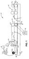
- FIG. 1 is a diagrammatic view of a roll-forming apparatus embodying the principles of the present invention, shown as a front elevational view of a left-hand machine;
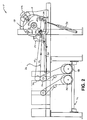
- FIG. 2 is a side-elevational view, similar to FIG. 1, shown as a back view of a left-hand machine, further illustrating the present roll-forming apparatus with certain components being omitted for clarity of illustration;
- FIG. 3 is a further side-elevational view of the present apparatus, shown as a back view of a left-hand machine, again with certain components omitted for clarity of illustration; and
- FIG. 4 is a diagrammatic view, shown as a back view of a left-hand machine, illustrating a drive arrangement for a turret assembly of the present roll-forming apparatus.
- While the present invention is susceptible of embodiment in various forms, there is shown in the drawings and will hereinafter be described a presently preferred embodiment, with the understanding that the present disclosure is to be considered as an exemplification of the invention, and is not intended to limit the invention to the specific embodiment illustrated.
- With reference to FIG 1, therein is illustrated a winding or roll-forming
apparatus 10 embodying the principles of the present invention. Many of the specific details of the present apparatus will be well-known to those familiar with the art, and thus, such details are omitted for clarity. As will be recognized,apparatus 10 is configured generally in accordance with U.S. Patent No. 5,197,727, to Lotto et al.,
and as such, the apparatus is configured to form individual rolls of material from elongated webs of material at high speed. In a typical application, each web of material comprises a plurality of elements, such as bags. For purposes of the present disclosure, reference to continuous webs of material contemplates those webs which may include individual elements joined in end-to-end relation, such as by perforated portions. In contrast, the present apparatus can be employed for handling webs of material which comprise a plurality of discrete, interleaved elements. For either application, the webs of material are formed from an endless web supplied to the apparatus. - While the present apparatus will be described in connection with roll-formation of elongated webs of bags or like elements, it is within the purview of the present invention that the present winding apparatus can be configured for roll-formation of a wide variety of goods, including folded banners, signs, bumper stickers, pre-cut tape segments, tubes of plastic or other material, woven products such as pre-cut bandages, as well as bags of widely varying sizes.
- Roll-forming
apparatus 10 includes aframe 12 which carries an infeedconveyor 14, a slow-down conveyor 16 positioned downstream thereof, and aturret assembly 18 positioned downstream of theconveyor 16. The turret assembly includes arotatable turret 19 driven for intermittent, indexed rotation, and a plurality ofspindles 20, respectively designated 20a, 20b, 20c, 20d, with respect to the indexed positions of the spindles. In particular,spindle 20a is positioned for transfer of a web of material from slow-down conveyor 16, and thus, is referred to as the transfer spindle. After transfer is effected, the spindle is rotatably indexed (clockwise, referring to the orientation of FIG. 1) to position of spindle 20b, where driven rotation of the spindle effects winding of the web of material, and roll-formation. Thus, the spindle in the position of 20b is the so-called winding spindle. After completion of roll-formation, indexing rotation ofturret 19 positions each spindle in the position ofspindle 20c, at which push-off of the completed roll is effected. After removal of the roll from the spindle, each spindle is positioned in an inactive position, represented byspindle 20d, prior to further indexing of each spindle to the position ofspindle 20a for effecting web transfer. - With reference now to FIG. 1, the sequence of operation of
apparatus 10 will be described. With flow of material through the apparatus, generally taking place in a right-to-left direction, referring to the orientation of FIG 1, an endless web of material is first received by infeedconveyor 14 between a pair of opposedinfeed nip rolls 26. The endless web of material is directed from nip rolls 26 to a pair of opposed separator rolls 28, which can be selectively moved toward each other for operative engagement with the endless web. Separator rolls 28 are operated at a peripheral speed greater than the peripheral speed of infeed niprolls 26, with engagement of the separator rolls with the endless web effecting subdivision of the web. If continuous webs of material (such as end-to-end bags) are to be formed, separator rolls 28 are operated so as to separate each "connected" web of material from the endless web being supplied to the apparatus. Perforations in the endless web, such as between the individual bags or other elements, facilitate separation of the webs of material, which are then directed through the apparatus to slow-downconveyor 16. - For many applications, it is desired that a web of material be formed having discrete, individual interleaved elements. For formation of interleaved webs, separator rolls 28 are operated so as to separate each element (as by tearing of the perforations in the web) from the adjacent ones of the elements in the endless web supplied to the apparatus. Depending upon the type of material being conveyed, the
infeed conveyor 14 may include one or more upper and lower conveyor belts or relatively narrow "ropes", with the infeed conveyor driven by an associated infeed conveyor drive 32. - Interleaving of the individual bags or other elements to form an interleaved web is effected as the material is moved from
infeed conveyor 14 to slow-downconveyor 16. The slow-downconveyor 16 includes a pair of opposed slow-down nip rolls 36 at the upstream end of the conveyor, with anose roll 38 positioned at the downstream end of the conveyor for cooperation with winding spindle 20b, as will be further described. Like the infeed conveyor, slow-downconveyor 16 may include one or more upper and lower conveyor belts orropes 40 for conveyance of the web material therethrough. - Interleaving of individual elements is effected by the provision of a blow-down
tube 42, a blow-uptube 44, and a vacuum box 46. Interleaving (i.e., overlapping of the discrete elements) is effected by operating the slow-downconveyor 16 at a speed slower thaninfeed conveyor 14. The speed differential between the conveyors provides the desired degree of interleaving. - Interleaving is effected during transfer of a discrete web element from
conveyor 14 toconveyor 16. As the leading edge of the web element is received between slow-down nip rolls 36, blow-downtube 42 is operated to direct pressurized air against the upper surface of the web element. In view of the speed differential between the infeed and slow-down conveyors, slack created in the web element results in a trailing portion of the element moving downwardly under the influence of the air from blow-downtube 42. As the trailing end of the element is released frominfeed conveyor 14, pressurized air from blow-downtube 42 urges the trailing portion of the element onto vacuum box 46. The vacuum box includes a foraminous surface which acts to hold the trailing portion of the web element in sliding disposition on the vacuum box. - Slow-down conveyor nip rolls 36 continue to draw the web element into the slow-down conveyor, even as it is held downwardly by the vacuum box 46. Concurrently, the next successive web element is being moved out of
infeed conveyor 14 toward the slow-downconveyor 16. Because the trailing portion of the previous web element is held downwardly on vacuum box 46, and by virtue of the speed differential of the infeed and slow-down conveyors, overlapping or interleaving of the leading and trailing portions of the successive web elements is effected. The desired interleaving is enhanced by direction of pressurized air from blow-uptube 44 against the lower surface of the leading portion of the successive web element, with the flow of air from blow-downtube 42 interrupted. As the overlapped portions of the successive web elements are drawn into slow-down nip rolls 36, the cycle of interleaving is repeated through the coordinated action of blow-downtube 42, vacuum box 46, and blow-uptube 44. - One feature of the present apparatus which provides enhanced versatility in comparison to previous arrangements is the provision of a separate conveyor drive 48 (FIG. 2) for the slow-down
conveyor 16. Rather than provide a single drive for all components of the present apparatus, the provision of aseparate conveyor drive 48 for the slow-down conveyor permits the degree of interleaving of the discrete web elements to be readily selectively varied. In a current embodiment,conveyor drive 48 comprises a speed-adjustable electric motor, preferably comprising a variable frequency AC drive such as comprising a Saftronics Model No. PCU40P701, available from Saftronics of Fort Meyers, Florida, and a standard AC induction motor. The reference speed input to the variable frequency AC drive is selected by a relay that is controlled by an associated programmable logic controller of the apparatus, a General Electric/Fanuc Series 90-30. When the selector switch of the controller is turned to the "interleaf mode", the speed reference comes from a potentiometer mounted on the operator panel. The amount of interleaf is controlled by the potentiometer by dialing down the speed of the variable frequency AC drive, and therefore the speed of the slow-down conveyor. This adjustment arrangement is infinitely variable for selecting the degree of interleaving of the web elements. - When continuous webs of material (without interleaved discrete elements) are being handled by the apparatus, the logic controller switches a relay so that the slow-down
conveyor drive 48 gets its speed reference from the infeed conveyor drive 32 through an output on the infeed drive which is proportional to its speed. The infeed drive 32 may include components as those described above for the slow-down conveyor drive. By this arrangement, the slow-down conveyor drive 32 follows the infeed drive exactly, or can be offset slightly through drive parameter settings, a fraction of a percent or higher or lower. This speed differential can be desirable for some specific film composition or thickness applications, but is ordinarily not necessary. While the use of variable frequency AC drives is presently preferred, it is to be understood that other types of drives capable of being coordinated within one-tenth of one percent could be alternately employed. - With further reference to FIG. 1, transfer of the leading edge of each web of material from the slow-down
conveyor 16 to thetransfer spindle 20a is effected by the cooperating action of amovable air horn 52, and amovable kick roll 54. Thespindle 20a (i.e., the transfer spindle) is positioned as shown, with indexed rotation ofturret 19 stopped so that the spindle is held in position. As will be further described, thespindle 20a is driven to rotate at a speed which is the same as the speed of the slow-downconveyor 16, thus facilitating transfer of the leading edge of a web of material to the transfer spindle. For most applications, it is desirable to provide each of thespindles 20 with suitable vacuum openings through which a vacuum is drawn when each spindle is positioned for transfer of material from slow-downconveyor 16. - In order to effect transfer of the leading edge of the web of material from the slow-down
conveyor 16 to thetransfer spindle 28, theair horn 52 is rotated to a position to generally cover the transfer spindle. When the leading edge of the web of material is just approaching the air horn, thekick roll 54 is moved upwardly to urge theconveyor belt 40 of the slow-downconveyor 16 upwardly toward thetransfer spindle 20a. At the same time, pressurized air is directed from the air horn onto the conveyor belt, thereby blowing the leading edge of the web of material generally upwardly onto the transfer spindle, with the vacuum drawn therethrough facilitating gripping of the leading edge of the web. Driven rotation of the transfer spindle effects initiation of roll-formation, with subsequent indexing movement of theturret 19 moving the transfer spindle to the winding spindle position for winding of the web of material received from slow-downconveyor 16. - With particular reference to FIGS. 2 and 3, the present invention employs a drive arrangement for the transfer spindle which acts to drive the spindle at substantially the same speed as the slow-down conveyor, as the leading edge of the web of material is transferred onto the spindle. While it is presently preferred that the transfer spindle be driven at the same speed as the slow-down conveyor, some applications may call for the speed of the spindle to vary slightly from the conveyor speed. In the presently preferred embodiment, this drive arrangement for the transfer spindle comprises a transfer drive belt 56 driven via a jackshaft 58 and an intermediate drive belt 60, which in turn are driven by the slow-down
conveyor drive 48. Thus, the speed of transfer drive belt 56 is directly proportional to the speed ofconveyor drive 48, thus effecting coordination of the speed of the transfer spindle with the speed of the slow-downconveyor 16. As illustrated in FIG. 3, thetransfer spindle 20a is in driven engagement with the transfer drive belt 56 when the spindle is in the transfer position. - While driven rotation of the transfer spindle is preferably effected mechanically from the
conveyor drive 48, it is within the purview of the present invention to instead provide a speed-adjustable motor for effecting driven rotation of the transfer spindle. This can be effected by the use of a variable frequency AC drive system, operated to control the speed of the transfer spindle by following the speed of the slow-downconveyor 16. Again, it is desired to effect control of the transfer spindle such that its peripheral or surface speed is the same as the surface speed of the slow-downconveyor 16. - Indexing movement of
turret assembly 18 is effected to move the transfer spindle to the position of winding spindle 20b. Driven rotation of the winding spindle effects roll-formation as the web of material is received from slow-downconveyor 16. - As noted above, the present apparatus includes a drive arrangement for the winding spindle which is separate from the slow-down
conveyor drive 48, as well as separate from other drives of the apparatus. This provides highly desirable versatility, permitting precise control of roll formation. To this end, the drive arrangement includes a windingdrive belt 64, and a winding drive motor 66 which effects driven movement of thedrive belt 64, and thus driven rotation of the winding spindle 20b. Idler 68 maintains the desired level of tension in the windingdrive belt 64. As will be noted by the disposition of windingdrive belt 64 relative to transfer drive belt 56, indexing movement of each spindle moves each spindle out of driven engagement with transfer drive belt 56, and into driven engagement with windingdrive belt 64. Again, this preferred arrangement obviates the need for use of externally toothed timing belts, thus permitting the spindles to be provided with non-toothed driven surfaces. Smooth, or knurled, drive surfaces for the spindles can be employed. - Drive of the winding arrangement can be effected through the use of a suitable electronic torque-controlled electric motor drive, such as a servo-drive operated in torque mode. In a current embodiment, a Danfoss Model 176B4000, DC 4 quadrant drive operating in torque mode, available from Danfoss Corp., of Rockford, Illinois. The motor is a one-third horsepower Bodine DC motor.
- A control arrangement is preferably provided for measuring the diameter of the roll of material being formed on the spindle 20b as the spindle is driven by winding motor 66, with the control arrangement preferably selectively varying the torque output of the drive motor in relation to the diameter of the roll of material being formed. To this end, nose roll 38 of slow-down
conveyor 16 is mounted on an elongated pivot arm 70 which in turn is operatively connected to aslide control potentiometer 72. For operation, a potentiometer is employed for setting the starting level torque of the motor 66, with theslide potentiometer 72 provided to measure the diameter of the roll being formed as the potentiometer is operated by movement of pivot arm 70. As the roll being formed gets larger, the torque level goes up from the additional input. The amount of influence that theslide potentiometer 72 effects is adjusted by an associated potentiometer on the operator panel. - Indexing movement of the
turret assembly 18 is preferably effected by a drive arrangement separate from the slow-downconveyor drive 48. In particular, anindexing motor 74 operates through aprimary drive 75, ajackshaft 76, and asecondary drive 78 to intermittently rotateturret 19 so thatspindles 20 are indexed in 90° increments between their various operating positions. In a current embodiment, an Indramat DKC servo-drive module, with an Indramat style MKDO70 motor, available from the Indramat Division of the Rexroth Corporation, of Wood Dale, Illinois have been employed. The DKC series drive allows pre-entered motion profiles to be executed from simple logic level inputs. The notable advantage of using a servo-motor is that no additional mechanical clamping of theturret 19 is required when the turret is in its stopped position. The current control system permits selection of one of three different turret index speeds via a selector switch. The possible turret index speeds are unlimited. The precise positioning capabilities of the servo-drive assures that the indexed position of the turret is exact, and repeated as the spindles are intermittently rotated. - After completion of roll-formation on the winding spindle 20b, the
turret assembly 18 is indexed so that the completed roll is presented to push-offpalm 22. At this position, designated byspindle 20c, the completed roll of material is axially displaced from the spindle by the push-offpalm 22. In order to facilitate such removal, the present apparatus is configured to effect reverse rotation of thespindle 20c, thus acting to "unscrew" the completed roll from the spindle. This driving of the spindle in a direction opposite to that in which the spindle is rotating during roll-formation is effected byspindle reversing motor 82 operating through spindle reversing drive belt 84. As in the case of transfer drive belt 56 and windingdrive belt 64, spindle reversing drive belt 84 is positioned to drivingly engage each spindle as each spindle is moved into position ofspindle 20c. Thespindle reversing motor 82 is operated intermittently, and for only a brief period of time, in order to effect slight reverse rotation of thespindle 20c. Ordinarily, no more than several reverse rotations of thespindle 20c are required for facilitating removal of the roll of material therefrom.
Claims (15)
- A roll-forming apparatus (10) for forming individual rolls of material from associated webs of material comprising:a conveyor (16) for sequentially receiving said associated webs of material;a conveyor drive (48) operatively connected to said conveyor for continuously driving said conveyor for advancing each said web of material along said conveyor; anda turret assembly (18) positioned downstream of said conveyor for sequentially receiving said webs of material from said conveyor, said turret assembly comprising a rotatable turret (19) having mounted thereon a plurality of roll-forming spindles (20) each rotatable relative to said turret, said turret being configured for intermittent, indexed rotation so that said spindles are successively presented to receive respective ones of said webs of material thereon from formation of said rolls of material,said apparatus including transfer drive means (56,58,60) mechanically driven by said conveyor drive for driving one of said spindles at substantially the same speed as said conveyor as a leading edge of one of said webs of material is transferred onto said one spindle to facilitate formation thereon of said roll of material.
- A roll-forming apparatus as claimed in claim 1, comprising:
winding drive means separate from said conveyor drive for driving each said spindle during formation of a roll of material thereon. - A roll-forming apparatus as claimed in claim 1 or 2, comprising:
turret drive means separate from said conveyor drive for intermittently driving said turret to index the spindles thereon. - A roll-forming apparatus as claimed in any of the preceding claims, comprising:
means for driving each said spindle in a direction opposite to that in which each spindle is rotated during roll-formation to facilitate removal of the roll of material from the spindle. - A roll-forming apparatus as claimed in any of the preceding claims, wherein
said transfer drive means comprises a transfer drive belt driven by said conveyor drive. - A roll-forming apparatus as claimed in claim 5, comprising:
winding drive means for driving each said spindle during formation of a roll of material thereon comprising a winding drive belt, each said spindle being moved, during indexed rotation of said turret, out of driven engagement with said transfer drive belt into driven engagement with said winding drive belt. - A roll-forming apparatus as claimed in claim 6, wherein
each said spindle comprises a non-toothed driven surface engageable with said transfer and winding drive belts. - A roll-forming apparatus (10) for forming individual rolls of material from associated webs of material, comprising;a conveyor (16) for sequentially receiving said associated webs of material;a conveyor drive (48) operatively connected to said conveyor for continuously driving said conveyor for advancing each said web of material along said conveyor; anda turret assembly (18) positioned downstream of said conveyor for sequentially receiving said webs of material from said conveyor, said turret assembly comprising a rotatable turret (19) having mounted thereon a plurality of roll-forming spindles (20) each rotatable relative to said turret, said turret being configured for intermittent, indexed rotation so that said spindles are successively presented to receive respective ones of said webs of material thereon from formation of said rolls of material,said apparatus including transfer drive means (56,58,60) for driving one of said spindles at substantially the same speed as said conveyor as a leading edge of one of said webs of material is transferred onto said one spindle to facilitate formation thereon of said roll of material, andmeans (66) separate from said conveyor drive for driving each said spindle during formation of a roll of material thereon.
- A roll-forming apparatus as claimed in claim 8, wherein
said transfer drive means comprises a speed-adjustable electric motor operatively connected to said conveyor drive. - A roll-forming apparatus as claimed in claim 8 or 9, wherein
said winding drive means comprises a torque-controlled electric motor. - A roll-forming apparatus as claimed in any of claims 8 to 10 comprising:
turret drive means separate from said conveyor drive and comprising a servo-controlled electric motor for intermittently driving said turret to index the spindles thereon. - A roll-forming apparatus as claimed in claim 8, wherein
said transfer drive means comprises a transfer drive belt, and said winding drive means comprises a winding drive belt, each said spindle being moved, during indexed rotation of said turret, out of driven engagement with said transfer drive belt and into driven engagement with said winding drive belt. - A roll-forming apparatus as claimed in any of claims 8 to 12 comprising:
means for measuring the diameter of the roll of material being formed on each spindle during driving by said winding drive means, and control means for selectively varying the torque output of said winding drive means in relation to the diameter of the roll of material being formed. - A roll-forming apparatus as claimed in any of claims 8 to 13 comprising:
means for driving each said spindle in a direction opposite to that in which each spindle is rotated during roll-formation to facilitate removal of the roll of material from the spindle. - A roll-forming apparatus as claimed in any of the preceding claims, wherein
said conveyor drive comprises a speed-adjustable electric motor operatively coupled to an associated infeed conveyor whereby said conveyor drive can be selectively adjusted relative to the speed of said infeed conveyor to selectively vary interleaving of a plurality of discrete elements forming each of said webs of material.
Applications Claiming Priority (2)
| Application Number | Priority Date | Filing Date | Title |
|---|---|---|---|
| US65680296A | 1996-05-31 | 1996-05-31 | |
| US656802 | 1996-05-31 |
Publications (2)
| Publication Number | Publication Date |
|---|---|
| EP0810172A2 true EP0810172A2 (en) | 1997-12-03 |
| EP0810172A3 EP0810172A3 (en) | 1998-08-19 |
Family
ID=24634632
Family Applications (1)
| Application Number | Title | Priority Date | Filing Date |
|---|---|---|---|
| EP97303696A Withdrawn EP0810172A3 (en) | 1996-05-31 | 1997-06-02 | Roll-forming apparatus for continuous or interleaved webs |
Country Status (5)
| Country | Link |
|---|---|
| EP (1) | EP0810172A3 (en) |
| JP (1) | JPH1072148A (en) |
| AU (1) | AU2369297A (en) |
| BR (1) | BR9703334A (en) |
| CA (1) | CA2205795A1 (en) |
Cited By (5)
| Publication number | Priority date | Publication date | Assignee | Title |
|---|---|---|---|---|
| EP0995708A2 (en) * | 1998-10-21 | 2000-04-26 | Cmd Corporation | Bag winder and method thereof |
| GB2476934A (en) * | 2010-01-13 | 2011-07-20 | Christoph Johann Schmitz | Apparatus and method for rolling webs using a plurality of rolling up stations |
| CN103895368A (en) * | 2012-12-25 | 2014-07-02 | 精工爱普生株式会社 | Recording device, take-up device, and method for taking up recording medium |
| US10494214B2 (en) | 2015-03-23 | 2019-12-03 | Jensen Denmark A/S | Wind-up apparatus for a web material |
| US10781046B2 (en) | 2016-12-16 | 2020-09-22 | Kimberly-Clark Worldwide, Inc. | Vacuum nose roll |
Citations (3)
| Publication number | Priority date | Publication date | Assignee | Title |
|---|---|---|---|---|
| US3116890A (en) * | 1961-08-01 | 1964-01-07 | Paper Converting Machine Co | Web winding apparatus |
| GB2242677A (en) * | 1990-04-04 | 1991-10-09 | Fmc Corp | Apparatus for rolling up web material |
| US5362013A (en) * | 1992-05-01 | 1994-11-08 | Custom Machinery Design, Inc. | Method and apparatus for interleaving plastic bags |
-
1997
- 1997-05-22 CA CA002205795A patent/CA2205795A1/en not_active Abandoned
- 1997-05-29 AU AU23692/97A patent/AU2369297A/en not_active Abandoned
- 1997-05-30 BR BR9703334A patent/BR9703334A/en not_active Application Discontinuation
- 1997-06-02 JP JP9144178A patent/JPH1072148A/en active Pending
- 1997-06-02 EP EP97303696A patent/EP0810172A3/en not_active Withdrawn
Patent Citations (3)
| Publication number | Priority date | Publication date | Assignee | Title |
|---|---|---|---|---|
| US3116890A (en) * | 1961-08-01 | 1964-01-07 | Paper Converting Machine Co | Web winding apparatus |
| GB2242677A (en) * | 1990-04-04 | 1991-10-09 | Fmc Corp | Apparatus for rolling up web material |
| US5362013A (en) * | 1992-05-01 | 1994-11-08 | Custom Machinery Design, Inc. | Method and apparatus for interleaving plastic bags |
Cited By (9)
| Publication number | Priority date | Publication date | Assignee | Title |
|---|---|---|---|---|
| EP0995708A2 (en) * | 1998-10-21 | 2000-04-26 | Cmd Corporation | Bag winder and method thereof |
| EP0995708A3 (en) * | 1998-10-21 | 2000-09-27 | Cmd Corporation | Bag winder and method thereof |
| GB2476934A (en) * | 2010-01-13 | 2011-07-20 | Christoph Johann Schmitz | Apparatus and method for rolling webs using a plurality of rolling up stations |
| CN103895368A (en) * | 2012-12-25 | 2014-07-02 | 精工爱普生株式会社 | Recording device, take-up device, and method for taking up recording medium |
| EP2749426A1 (en) * | 2012-12-25 | 2014-07-02 | Seiko Epson Corporation | Recording device, take-up device, and method for taking up recording medium |
| US9359162B2 (en) | 2012-12-25 | 2016-06-07 | Seiko Epson Corporation | Recording device, take-up device, and method for taking up recording medium |
| CN103895368B (en) * | 2012-12-25 | 2017-07-28 | 精工爱普生株式会社 | The method for coiling of tape deck, devices for taking-up and printing medium |
| US10494214B2 (en) | 2015-03-23 | 2019-12-03 | Jensen Denmark A/S | Wind-up apparatus for a web material |
| US10781046B2 (en) | 2016-12-16 | 2020-09-22 | Kimberly-Clark Worldwide, Inc. | Vacuum nose roll |
Also Published As
| Publication number | Publication date |
|---|---|
| AU2369297A (en) | 1997-12-04 |
| EP0810172A3 (en) | 1998-08-19 |
| CA2205795A1 (en) | 1997-11-30 |
| BR9703334A (en) | 1998-09-22 |
| JPH1072148A (en) | 1998-03-17 |
Similar Documents
| Publication | Publication Date | Title |
|---|---|---|
| US4730762A (en) | Process and equipment for manufacturing individual stacks consisting of a length of material folded in zig zag form | |
| US5979729A (en) | Separating a web at a line of weakness | |
| US5373761A (en) | Method for perforation of a sheet material | |
| US4219988A (en) | Automatic high-speed wrapping machine | |
| US6267034B1 (en) | Apparatus for cutting and stacking a multi-form web | |
| JP2809388B2 (en) | Stack formation and delivery device | |
| US4297066A (en) | Paper sheet layer forming and transferring arrangement | |
| JPS61183035A (en) | One-sheet feeder for packing paper | |
| CA2056947A1 (en) | Folder for a printing machine with a device for slowing down signatures sent to a quarter fold of said folder | |
| JPS62244864A (en) | Sheet material accumulating device | |
| US5388746A (en) | Separator/folder bag machine | |
| EP0810172A2 (en) | Roll-forming apparatus for continuous or interleaved webs | |
| JPS60244753A (en) | Laminating device for printing paper | |
| DE60300670T2 (en) | Method for starting and stopping a packaging machine during a production change | |
| US20040242394A1 (en) | Web folding machine | |
| US4683704A (en) | Method of and apparatus for wrapping | |
| US4261779A (en) | Indexing roll drive system | |
| US4190243A (en) | Folder assembly for book folding | |
| US3690997A (en) | Apparatus for securing strip members to container bodies | |
| EP1580155B1 (en) | Winder apparatus with transfer brush roll | |
| US5338281A (en) | Wicket servo method and device in a bag making machine | |
| US5899403A (en) | Method and apparatus for winding bags onto a spindle | |
| EP0162628B1 (en) | Folding apparatus | |
| US5961020A (en) | Separating a web at a line of weakness | |
| US4077306A (en) | Bag machine cycle interrupt |
Legal Events
| Date | Code | Title | Description |
|---|---|---|---|
| PUAI | Public reference made under article 153(3) epc to a published international application that has entered the european phase |
Free format text: ORIGINAL CODE: 0009012 |
|
| AK | Designated contracting states |
Kind code of ref document: A2 Designated state(s): BE DE DK ES FR GB IT |
|
| AX | Request for extension of the european patent |
Free format text: AL;LT;LV;RO;SI |
|
| PUAL | Search report despatched |
Free format text: ORIGINAL CODE: 0009013 |
|
| AK | Designated contracting states |
Kind code of ref document: A3 Designated state(s): AT BE CH DE DK ES FI FR GB GR IE IT LI LU MC NL PT SE |
|
| AX | Request for extension of the european patent |
Free format text: AL;LT;LV;RO;SI |
|
| 17P | Request for examination filed |
Effective date: 19990218 |
|
| AKX | Designation fees paid |
Free format text: AT BE DE DK FR GB IT |
|
| RBV | Designated contracting states (corrected) |
Designated state(s): AT BE DE DK FR GB IT |
|
| RBV | Designated contracting states (corrected) |
Designated state(s): BE DE DK ES FR GB IT |
|
| 17Q | First examination report despatched |
Effective date: 19991207 |
|
| STAA | Information on the status of an ep patent application or granted ep patent |
Free format text: STATUS: THE APPLICATION HAS BEEN WITHDRAWN |
|
| 18W | Application withdrawn |
Withdrawal date: 20000308 |