EP0810159B1 - Cork cap - Google Patents
Cork cap Download PDFInfo
- Publication number
- EP0810159B1 EP0810159B1 EP97101362A EP97101362A EP0810159B1 EP 0810159 B1 EP0810159 B1 EP 0810159B1 EP 97101362 A EP97101362 A EP 97101362A EP 97101362 A EP97101362 A EP 97101362A EP 0810159 B1 EP0810159 B1 EP 0810159B1
- Authority
- EP
- European Patent Office
- Prior art keywords
- cork
- head
- cap
- leg
- hole
- Prior art date
- Legal status (The legal status is an assumption and is not a legal conclusion. Google has not performed a legal analysis and makes no representation as to the accuracy of the status listed.)
- Expired - Lifetime
Links
Images


Classifications
-
- B—PERFORMING OPERATIONS; TRANSPORTING
- B65—CONVEYING; PACKING; STORING; HANDLING THIN OR FILAMENTARY MATERIAL
- B65D—CONTAINERS FOR STORAGE OR TRANSPORT OF ARTICLES OR MATERIALS, e.g. BAGS, BARRELS, BOTTLES, BOXES, CANS, CARTONS, CRATES, DRUMS, JARS, TANKS, HOPPERS, FORWARDING CONTAINERS; ACCESSORIES, CLOSURES, OR FITTINGS THEREFOR; PACKAGING ELEMENTS; PACKAGES
- B65D39/00—Closures arranged within necks or pouring openings or in discharge apertures, e.g. stoppers
- B65D39/16—Closures arranged within necks or pouring openings or in discharge apertures, e.g. stoppers with handles or other special means facilitating manual actuation
Definitions
- This invention relates to a cork cap which is inserted in a bottle mouth before plugging a cork. Once the cork is plugged, the bottle mouth is completely sealed as with an ordinary bottle plugged solely with a cork. The cork can be pulled out together with the cork cap simply by pulling the cork cap without using a corkscrew or any other bottle opener.
- a cork cap of the above-mentioned type which makes it possible to pull out a cork plugged in e.g. a wine bottle simply by pulling the cork cap with both hands without using a cork screw (Examined Japanese Utility Model Publication 4-27836 and Unexamined Japanese Patent Publication 8-40446).
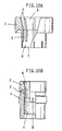
- Fig. 10 shows this cork cap.
- It is a plastic molding comprising a head 2 having an outer diameter greater than the inner diameter of a bottle mouth 1, and a leg 3 provided concentrically with the head 2 and having an outer diameter substantially equal to the inner diameter of the bottle mouth 1.
- the entire length of the cork cap i.e. the sum of the lengths of the head 2 and the leg 3, is shorter than the length of the cork 4.
- the cork 4 is press-fitted into a hole 5 formed through the head 2 and the leg 3.
- Part of the hole 5 formed in the head 2 is tapered so that its diameter increases gradually upward.
- a plurality of vertical ribs 6 are provided on the inner periphery of the hole 5, extending from the head 2 to the leg 3.
- the cork 4 With the leg 3 of the cork cap inserted in the bottle mouth 1, the cork 4 is plugged into the bottle mouth 1. In this state, the portion of the cork 4 protruding downward from the leg 3 is pressed hard against the inner surface of the bottle mouth 1, sealing the bottle mouth 1. The cork 4 can be pulled out simply by holding the head 2 of the cork cap and pulling it.
- a slit 8 is shown to be formed in a thin portion 7 of the leg 3.
- the tapered inner surface of the hole formed in the head 2 mainly serves this purpose. That is, the tapered surface prevents the cap from separating from the cork when the former is pulled out.
- the vertical ribs 6 increase the frictional force between the cap and the cork when the former is turned.
- An object of this invention is to increase the resistance to the force that acts to separate the cork and the cork cap when a pulling force is applied to the latter by providing the cap with means that can strongly bite the cork.
- a cork cap for a bottle comprising a head having an outer diameter greater than the inner diameter of the mouth of the bottle, a leg provided concentrically with the head and having an outer diameter substantially equal to the inner diameter of the bottle mouth, the head and leg having lengths, the sum of which is smaller than the length of a cork, the cork cap being formed with a hole extending through the head and the leg, the hole formed in the head being tapered radially outwardly from its bottom to top, a plurality of vertical ribs formed on the inner surface of the hole and extending vertically from the head to the leg, and means for preventing the separation of the cork cap from the cork when the cork cap is pulled to remove the cork, said means being formed so as to protrude radially inwardly from the tapered inner surface of said hole or from the surface of said respective vertical ribs at their portions disposed in said head.
- protrusions may be formed each on the inner surface of the portion of the hole formed in the head between adjacent ones of the vertical ribs, each of the protrusions having a lower front surface extending vertically or tapered radially outwardly from its bottom to top, and an upper front surface connecting at its bottom with the top of the lower front surface along a horizontal ridge and tapered radially outwardly toward its top from the ridge.
- each of the vertical ribs may be formed with a radially inwardly protruding step at its portion disposed in the head.
- the cork can be more strongly coupled to the cork cap than in conventional arrangements.
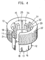
- Figs. 1-3 show a cork cap of the first embodiment, which is, like the conventional cap, a plastic molding. It comprises a head 11, a leg 12 concentrically provided at the bottom end of head 11, and a cover 13 integrally connected to the top of the head 11.
- the head 11 is tapered so that its inner diameter is greater at the top than at the bottom. Its outer diameter at its bottom is greater than the inner diameter of a bottle mouth 14 (see Fig. 3) so that the bottom of the head 11 rests on the bottle mouth 14.
- the leg 12 is cylindrical and has an outer diameter substantially equal to the inner diameter of the bottle mouth 14.
- a hole 15 is formed through the head 11 and the leg 12. Its portion formed in the head 11 is tapered so that its diameter increases gradually upward. Its portion at the bottom of the leg 12 is tapered so that its diameter increases gradually downward. Thus, the wall of the leg 12 is thin at the bottom.
- the thin portion 16 of the leg is formed with a plurality of slits 17 extending vertically from the bottom end of the leg.
- a V-shaped groove 18 is formed so as to connect with the top end of each slit 17.
- the cover 13 comprises a flange 19 extending radially outwardly from the top of the head 11, and a cylindrical portion 21 extending downward from the outer edge of the flange 19.
- the cylindrical portion 21 extends to a level near the top end of the thin portion 16 of the leg 12, covering the bottle mouth 14 (Fig. 3).
- a nonslip surface 22 is formed on the outer periphery of the cylindrical portion 21.
- Reinforcing radial ribs 23 are provided, circumferentially spaced from each other, between the outer periphery of the head 11 and the inner periphery of the cylindrical portion 21 (Fig. 2B).
- the sum of the lengths of the head 11 and the leg 12 is shorter than the length of the cork 4 (Fig. 3).
- a required number of vertical ribs 25 are formed at required circumferential intervals on the inner periphery of the head 11 and the leg 12.
- the ribs 25 extend to the top end of the thin portion 16 of the leg 12. They have a triangular section (Fig. 2B).
- Horizontal ribs 26 are formed on the inner periphery of the head 11 between and spaced from the adjacent vertical ribs 25.
- the horizontal ribs 26 have a triangular section with a horizontal bottom 26a and an inclined top surface 26b, as shown in Fig. 2A. They are slightly higher than the portions of the vertical ribs 25 at the level of the horizontal ribs 26 (Fig. 2B).
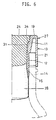
- the cork 24 In use, with the leg 12 of the cork cap 27 (Fig. 3) inserted in the bottle mouth 14 and the head 11 resting on the bottle mouth 14, the cork 24 is plugged in.
- the cork 24 is an ordinary column-shaped cork. It is compressed when it passes through the leg 12. When its bottom end 28 protrudes from the bottom end of the leg 12, it expands to be pressed hard against the inner periphery of the bottle mouth 14, sealing the bottle mouth. If the bottle mouth 14 is slightly oversized, the slits 17 will widen and the V-shaped grooves 18 may be torn, thereby spreading the leg's bottom.
- the tapered inner surface and the horizontal ribs 26 formed on the head 11 will keep the cork strongly coupled to the cork cap when the cork cap 27 is pulled up.
- the vertical ribs 25 allow the cork 24 to rotate with the cork cap 27 when the latter is twisted. Thus, by pulling the cork cap 27 while twisting it by hand, the cork 24 together with the cork cap 27 can be pulled out of the bottle mouth 14.
- the horizontal ribs 26 of the first embodiment are inversely tapered, so that a complicated mold has to be used to form the cork cap 27.
- the second embodiment shown in Figs. 4-6 is free of this problem.
- protrusions 31 are formed on the inner periphery of the head 11 between the adjacent vertical ribs 25. They are long in the vertical direction and have a constant width over the entire length. Each protrusion 31 has a lower front surface 33 extending vertically upward from the bottom end of the head 11 (Fig. 5A), and a tapered upper front surface 34 extending obliquely upwardly so that its top end is radially outside of its bottom end. A horizontal ridge 32 is defined between the lower and upper surfaces 33 and 34.
- the lower front surface 33 may be tapered radially outward from its bottom toward the ridge 32.
- the cork cap of this embodiment can be formed using a less complicated mold.
- the upper front surface 34 of each protrusion 31 serves to keep the cork 24 strongly coupled to the cork cap when the latter is pulled.
- Figs. 7 to 9 show the third embodiment, in which each vertical rib 25 has a radially inwardly extending step 35 midway of its length. Since the ribs 25 have a V-shaped cross-section, the steps 35 are also V-shaped as viewed from top (Fig. 8B). The steps 35 also serve to keep the cork strongly coupled to the cork cap when the latter is pulled. Otherwise, this embodiment is the same as the first embodiment.
- the horizontal ribs, protrusions and steps formed on the inner periphery of the head of the cork cap increase the force with which the cork is coupled to the cork cap when the latter is pulled, thus making it possible to pull out the cork together with the cap with high reliability.
Landscapes
- Engineering & Computer Science (AREA)
- Mechanical Engineering (AREA)
- Closures For Containers (AREA)
- Devices For Opening Bottles Or Cans (AREA)
Description
- This invention relates to a cork cap which is inserted in a bottle mouth before plugging a cork. Once the cork is plugged, the bottle mouth is completely sealed as with an ordinary bottle plugged solely with a cork. The cork can be pulled out together with the cork cap simply by pulling the cork cap without using a corkscrew or any other bottle opener.
- The inventor of this application proposed a cork cap of the above-mentioned type which makes it possible to pull out a cork plugged in e.g. a wine bottle simply by pulling the cork cap with both hands without using a cork screw (Examined Japanese Utility Model Publication 4-27836 and Unexamined Japanese Patent Publication 8-40446). Fig. 10 shows this cork cap.
- It is a plastic molding comprising a
head 2 having an outer diameter greater than the inner diameter of abottle mouth 1, and aleg 3 provided concentrically with thehead 2 and having an outer diameter substantially equal to the inner diameter of thebottle mouth 1. The entire length of the cork cap, i.e. the sum of the lengths of thehead 2 and theleg 3, is shorter than the length of thecork 4. Thecork 4 is press-fitted into ahole 5 formed through thehead 2 and theleg 3. - Part of the
hole 5 formed in thehead 2 is tapered so that its diameter increases gradually upward. A plurality ofvertical ribs 6 are provided on the inner periphery of thehole 5, extending from thehead 2 to theleg 3. - With the
leg 3 of the cork cap inserted in thebottle mouth 1, thecork 4 is plugged into thebottle mouth 1. In this state, the portion of thecork 4 protruding downward from theleg 3 is pressed hard against the inner surface of thebottle mouth 1, sealing thebottle mouth 1. Thecork 4 can be pulled out simply by holding thehead 2 of the cork cap and pulling it. - In the figure, a
slit 8 is shown to be formed in athin portion 7 of theleg 3. - When a cork is plugged in a bottle mouth with the above cork cap inserted in the bottle mouth, the bottle mouth is sealed by the
cork 4. The content of the bottle such as wine can perspire through thecork 4. The cork cap plays no role in these functions. - Problem is how to pull out the cork reliably by pulling the cork cap. In the above conventional arrangement, the tapered inner surface of the hole formed in the
head 2 mainly serves this purpose. That is, the tapered surface prevents the cap from separating from the cork when the former is pulled out. Thevertical ribs 6 increase the frictional force between the cap and the cork when the former is turned. - But it is desired to couple the cap and the cork more rigidly to prevent the cap from separating from the cork when the former is pulled.
- An object of this invention is to increase the resistance to the force that acts to separate the cork and the cork cap when a pulling force is applied to the latter by providing the cap with means that can strongly bite the cork.
- According to this invention, there is provided a cork cap for a bottle comprising a head having an outer diameter greater than the inner diameter of the mouth of the bottle, a leg provided concentrically with the head and having an outer diameter substantially equal to the inner diameter of the bottle mouth, the head and leg having lengths, the sum of which is smaller than the length of a cork, the cork cap being formed with a hole extending through the head and the leg, the hole formed in the head being tapered radially outwardly from its bottom to top, a plurality of vertical ribs formed on the inner surface of the hole and extending vertically from the head to the leg, and means for preventing the separation of the cork cap from the cork when the cork cap is pulled to remove the cork, said means being formed so as to protrude radially inwardly from the tapered inner surface of said hole or from the surface of said respective vertical ribs at their portions disposed in said head.
- Instead of the horizontal ribs, protrusions may be formed each on the inner surface of the portion of the hole formed in the head between adjacent ones of the vertical ribs, each of the protrusions having a lower front surface extending vertically or tapered radially outwardly from its bottom to top, and an upper front surface connecting at its bottom with the top of the lower front surface along a horizontal ridge and tapered radially outwardly toward its top from the ridge.
- Instead of such horizontal ribs or protrusions, each of the vertical ribs may be formed with a radially inwardly protruding step at its portion disposed in the head.
- In any of the arrangements, the cork can be more strongly coupled to the cork cap than in conventional arrangements.
- Other features and objects of the present invention will become apparent from the following description made with reference to the accompanying drawings, in which:
-
- Fig. 1 is a partially cutaway perspective view of a first embodiment;
- Fig. 2A is a sectional view of the same;
- Fig. 2B is a partial sectional view taken along line b-b of Fig. 2A;
- Fig. 3 is a partial enlarged sectional view of the same showing how it is used;
- Fig. 4 is a partially cutaway perspective view of a second embodiment;
- Fig. 5A is a sectional view of the same;
- Fig. 5B is a sectional view taken along line b-b of Fig. 5A;
- Fig. 6 is a partial enlarged sectional view of the same showing how it is used;
- Fig. 7 is a partially cutaway perspective view of a third embodiment;
- Fig. 8A is a sectional view of the same;
- Fig. 8B is a sectional view taken along line b-b of Fig. 8A;
- Fig. 9 is a partial enlarged sectional view of the same showing how it is used;
- Fig. 10A is a sectional view of the prior art; and
- Fig. 10B is a sectional view of the same as used with a cork.
-
- Figs. 1-3 show a cork cap of the first embodiment, which is, like the conventional cap, a plastic molding. It comprises a
head 11, aleg 12 concentrically provided at the bottom end ofhead 11, and acover 13 integrally connected to the top of thehead 11. - The
head 11 is tapered so that its inner diameter is greater at the top than at the bottom. Its outer diameter at its bottom is greater than the inner diameter of a bottle mouth 14 (see Fig. 3) so that the bottom of thehead 11 rests on thebottle mouth 14. Theleg 12 is cylindrical and has an outer diameter substantially equal to the inner diameter of thebottle mouth 14. - A
hole 15 is formed through thehead 11 and theleg 12. Its portion formed in thehead 11 is tapered so that its diameter increases gradually upward. Its portion at the bottom of theleg 12 is tapered so that its diameter increases gradually downward. Thus, the wall of theleg 12 is thin at the bottom. Thethin portion 16 of the leg is formed with a plurality ofslits 17 extending vertically from the bottom end of the leg. A V-shapedgroove 18 is formed so as to connect with the top end of each slit 17. - The
cover 13 comprises aflange 19 extending radially outwardly from the top of thehead 11, and acylindrical portion 21 extending downward from the outer edge of theflange 19. Thecylindrical portion 21 extends to a level near the top end of thethin portion 16 of theleg 12, covering the bottle mouth 14 (Fig. 3). Anonslip surface 22 is formed on the outer periphery of thecylindrical portion 21. - Reinforcing
radial ribs 23 are provided, circumferentially spaced from each other, between the outer periphery of thehead 11 and the inner periphery of the cylindrical portion 21 (Fig. 2B). - The sum of the lengths of the
head 11 and theleg 12 is shorter than the length of the cork 4 (Fig. 3). A required number ofvertical ribs 25 are formed at required circumferential intervals on the inner periphery of thehead 11 and theleg 12. Theribs 25 extend to the top end of thethin portion 16 of theleg 12. They have a triangular section (Fig. 2B). -
Horizontal ribs 26 are formed on the inner periphery of thehead 11 between and spaced from the adjacentvertical ribs 25. Thehorizontal ribs 26 have a triangular section with ahorizontal bottom 26a and an inclinedtop surface 26b, as shown in Fig. 2A. They are slightly higher than the portions of thevertical ribs 25 at the level of the horizontal ribs 26 (Fig. 2B). - In use, with the
leg 12 of the cork cap 27 (Fig. 3) inserted in thebottle mouth 14 and thehead 11 resting on thebottle mouth 14, thecork 24 is plugged in. Thecork 24 is an ordinary column-shaped cork. It is compressed when it passes through theleg 12. When itsbottom end 28 protrudes from the bottom end of theleg 12, it expands to be pressed hard against the inner periphery of thebottle mouth 14, sealing the bottle mouth. If thebottle mouth 14 is slightly oversized, theslits 17 will widen and the V-shapedgrooves 18 may be torn, thereby spreading the leg's bottom. - As the
cork 24 is pushed into the bottle mouth, it is deformed along the tapered inner surface of thehead 11, while the vertical andhorizontal ribs cork 24. - The tapered inner surface and the
horizontal ribs 26 formed on thehead 11 will keep the cork strongly coupled to the cork cap when thecork cap 27 is pulled up. Thevertical ribs 25 allow thecork 24 to rotate with thecork cap 27 when the latter is twisted. Thus, by pulling thecork cap 27 while twisting it by hand, thecork 24 together with thecork cap 27 can be pulled out of thebottle mouth 14. - The
horizontal ribs 26 of the first embodiment are inversely tapered, so that a complicated mold has to be used to form thecork cap 27. The second embodiment shown in Figs. 4-6 is free of this problem. - In the second embodiment,
protrusions 31 are formed on the inner periphery of thehead 11 between the adjacentvertical ribs 25. They are long in the vertical direction and have a constant width over the entire length. Eachprotrusion 31 has a lowerfront surface 33 extending vertically upward from the bottom end of the head 11 (Fig. 5A), and a tapered upperfront surface 34 extending obliquely upwardly so that its top end is radially outside of its bottom end. Ahorizontal ridge 32 is defined between the lower andupper surfaces - The lower
front surface 33 may be tapered radially outward from its bottom toward theridge 32. - Since the
protrusions 31 are not inversely tapered, the cork cap of this embodiment can be formed using a less complicated mold. The upperfront surface 34 of eachprotrusion 31 serves to keep thecork 24 strongly coupled to the cork cap when the latter is pulled. - Otherwise, this embodiment is the same as the first embodiment.
- Figs. 7 to 9 show the third embodiment, in which each
vertical rib 25 has a radially inwardly extendingstep 35 midway of its length. Since theribs 25 have a V-shaped cross-section, thesteps 35 are also V-shaped as viewed from top (Fig. 8B). Thesteps 35 also serve to keep the cork strongly coupled to the cork cap when the latter is pulled. Otherwise, this embodiment is the same as the first embodiment. - The horizontal ribs, protrusions and steps formed on the inner periphery of the head of the cork cap increase the force with which the cork is coupled to the cork cap when the latter is pulled, thus making it possible to pull out the cork together with the cap with high reliability.
Claims (4)
- A cork cap for a bottle comprising a head (11) having an outer diameter greater than the inner diameter of the mouth (14) of the bottle, a leg (12) provided concentrically with said head (11) and having an outer diameter substantially equal to the inner diameter of the bottle mouth (14) said head (11) and leg (12) having lengths, the sum of which is smaller than the length of a cork, said cork cap being formed with a hole (15) extending through said head (11) and said leg (12), said hole (15) formed in said head being tapered radially outwardly from its bottom to top, a plurality of vertical ribs (25) formed on the inner surface of said hole (15) and extending vertically from said head to said leg
characterized in that,
means (26, 31, 35) are provided for preventing the separation of said cork cap from the cork when said cork cap is pulled to remove the cork, said means being formed so as to protrude radially inwardly from the tapered inner surface of said hole (15) or from the surface of said respective vertical ribs (25) at their portion disposed in the head. - The cork cap as claimed in claim 1, wherein said means comprises a plurality of horizontal ribs (26) each formed on the inner surface of said hole formed in said head between adjacent ones of said vertical ribs (25).
- The cork cap as claimed in claim 1, wherein said means comprises a plurality of protrusions (31) each formed on the inner surface of said hole formed in said head between adjacent ones of said vertical ribs (25), each of said protrusions (31) having a lower front (33) surface extending vertically or tapered radially outwardly from its bottom to top, and an upper front surface (34) connecting at its bottom with the top of said lower front surface along a horizontal ridge (32) and tapered radially outwardly toward its top from ridge and tapered radially outwardly toward its top from said ridge.
- The cork cap as claimed in claim 1, wherein said means comprises a radially inwardly protruding step (35) formed on each of said vertical ribs (25) at its portion disposed in said head.
Applications Claiming Priority (3)
| Application Number | Priority Date | Filing Date | Title |
|---|---|---|---|
| JP133622/96 | 1996-05-28 | ||
| JP8133622A JPH09315450A (en) | 1996-05-28 | 1996-05-28 | Cork stopper cap |
| JP13362296 | 1996-05-28 |
Publications (2)
| Publication Number | Publication Date |
|---|---|
| EP0810159A1 EP0810159A1 (en) | 1997-12-03 |
| EP0810159B1 true EP0810159B1 (en) | 2002-08-07 |
Family
ID=15109132
Family Applications (1)
| Application Number | Title | Priority Date | Filing Date |
|---|---|---|---|
| EP97101362A Expired - Lifetime EP0810159B1 (en) | 1996-05-28 | 1997-01-29 | Cork cap |
Country Status (6)
| Country | Link |
|---|---|
| US (1) | US5803285A (en) |
| EP (1) | EP0810159B1 (en) |
| JP (1) | JPH09315450A (en) |
| DE (1) | DE69714516T2 (en) |
| ES (1) | ES2181937T3 (en) |
| PT (1) | PT810159E (en) |
Families Citing this family (27)
| Publication number | Priority date | Publication date | Assignee | Title |
|---|---|---|---|---|
| JP4349696B2 (en) * | 1999-08-11 | 2009-10-21 | 日本クラウンコルク株式会社 | Container lid comprising a combination of a gripping member and a sealing member |
| US6223937B1 (en) | 1999-11-17 | 2001-05-01 | Kevin Schmidt | Portable dispensing bottle with dissolvable wax plug at inlet |
| FR2804940B1 (en) * | 2000-02-10 | 2002-08-30 | Au Liegeur Ets J Pontneau Deni | CAP FOR BOTTLES WITH SPARKLING WINES AND METHOD FOR MANUFACTURING SUCH A CAP |
| JP2002326644A (en) * | 2001-04-27 | 2002-11-12 | Nissui Pharm Co Ltd | Cap |
| WO2004060762A1 (en) * | 2002-11-21 | 2004-07-22 | Jung-Min Lee | Spout assembly with a rubber or cork plug |
| WO2005110600A2 (en) * | 2004-05-18 | 2005-11-24 | Nunc A/S | Tube, cap and rack for automatic handling of samples |
| TWM259770U (en) * | 2004-05-19 | 2005-03-21 | Wu-Jang Shie | Cup cover structure |
| DE102004026964B3 (en) * | 2004-06-02 | 2005-10-27 | Alcoa Deutschland Gmbh | closure element |
| ES2265230B1 (en) * | 2004-07-13 | 2007-12-01 | Pablo Erice Irurita | BOTTLE CLOSURE PROCESS AND INCORPORABLE CAPSULE IN SUCH CLOSURE. |
| ITMI20051127A1 (en) * | 2005-06-15 | 2006-12-16 | Guala Dispensing Spa | CLOSURE FOR CONTAINERS, IN PARTICULAR FOR CHAMPAGNE OR SIMILAR WINE BOTTLES |
| JP2007008499A (en) * | 2005-06-29 | 2007-01-18 | Toppan Printing Co Ltd | Spouting plug for use of liquid container |
| USD587800S1 (en) | 2006-04-14 | 2009-03-03 | Resmed Limited | Respiratory mask cushion frame |
| US20070277482A1 (en) * | 2006-06-01 | 2007-12-06 | Lloydco, Llc | Re-sealing device |
| US20080073399A1 (en) * | 2006-09-26 | 2008-03-27 | David Rosenblum | Lighter socket pen holder |
| US7748293B2 (en) * | 2008-05-08 | 2010-07-06 | Michael Peter Elwell | Pill container opener |
| MX343643B (en) * | 2009-04-10 | 2016-11-15 | Tapones Escobar S A * | Glued synthetic cork and method of manufacture. |
| TWI369324B (en) * | 2009-09-29 | 2012-08-01 | Sunlot Bottle Strpper Co Ltd | A stopper structure |
| US8915167B2 (en) | 2011-02-10 | 2014-12-23 | Aleksandar Ratajac | Cork screw |
| JP6030196B1 (en) * | 2015-08-07 | 2016-11-24 | 株式会社パックプラス | Spout |
| US20170073122A1 (en) * | 2015-09-12 | 2017-03-16 | Karl Andrew Thomason | Screw top cork - scork |
| US10940086B2 (en) * | 2015-11-12 | 2021-03-09 | Scalpal Llc | Bottle support and protective collar |
| US20170174491A1 (en) * | 2015-12-17 | 2017-06-22 | Austin Robert Thomas FONTAINE | Integrated Bottle Opener for Sports and Other Equipment |
| USD815277S1 (en) * | 2016-11-30 | 2018-04-10 | Koninklijke Philips N.V. | Adaptor for positive airway pressure tube |
| EP3612459A1 (en) * | 2017-04-21 | 2020-02-26 | Guala Closures S.p.A. | Stopper with overcap for containers |
| PT110068B (en) * | 2017-05-10 | 2024-01-02 | Amorim Cork Res Lda | CAPSULE FOR FLANGEED CORK STOPPER, CAPSULATED STOPPER INCLUDING SAID CAPSULE AND PRODUCTION PROCESS OF THE CAPSULATED CORK STOPPER. |
| CN109372989B (en) * | 2018-11-22 | 2023-10-31 | 武汉市农业科学院 | Multifunctional plug for water inlet and outlet of aquaculture water |
| MX2022005486A (en) * | 2019-11-06 | 2022-05-30 | Compania De Tapones Irrellenables S A | Cap for an opening of a container. |
Family Cites Families (15)
| Publication number | Priority date | Publication date | Assignee | Title |
|---|---|---|---|---|
| GB324300A (en) * | 1929-04-26 | 1930-01-23 | Herbert Roy Davis | Improvements in and relating to stoppers for bottles, jars or other receptacles |
| FR803505A (en) * | 1936-03-17 | 1936-10-02 | Arts Plastiques Soc Ind Des | Method of fixing a cap on a cork stopper and resulting new object |
| FR799790A (en) * | 1936-05-26 | 1936-06-19 | Larrieu La Girondine Ets | Mechanical device allowing the shaping of the so-called "advertisement" caps with the simultaneous corking of the bottles |
| GB640216A (en) * | 1948-07-08 | 1950-07-12 | Kork N Seal Ltd | Improvements in or relating to closures for bottles and like containers |
| US2641375A (en) * | 1948-07-08 | 1953-06-09 | Kork N Seal Ltd | Closure for bottles and like containers |
| DE809040C (en) * | 1949-05-11 | 1951-07-23 | Josef Wutzer | Handle for bottle corks to remove the latter from the bottle |
| FR1121397A (en) * | 1955-03-28 | 1956-08-13 | Carpene Malvolti | Stopper for bottles of wine and similar liquids |
| US3638821A (en) * | 1970-04-01 | 1972-02-01 | Angelo Guala Di Piergiocomo & | Closure for bottles and similar containers |
| US4182458A (en) * | 1978-03-13 | 1980-01-08 | Milton Meckler | Wine bottle stopper |
| US4394922A (en) * | 1980-03-03 | 1983-07-26 | The West Company | Rubber stopper with plastic pull ring |
| DE3521866A1 (en) * | 1985-06-19 | 1987-01-02 | Toth Willy | Plastic stopper for wine bottles |
| US4932543A (en) * | 1989-01-03 | 1990-06-12 | Don Martus | Chambered bottle cap |
| JPH0427836U (en) | 1990-06-28 | 1992-03-05 | ||
| US5385253A (en) * | 1992-09-02 | 1995-01-31 | Baxter International Inc. | Port closure |
| JP2951543B2 (en) | 1994-07-27 | 1999-09-20 | 幸司 広田 | Cork stopper cap |
-
1996
- 1996-05-28 JP JP8133622A patent/JPH09315450A/en active Pending
-
1997
- 1997-01-29 DE DE69714516T patent/DE69714516T2/en not_active Expired - Fee Related
- 1997-01-29 ES ES97101362T patent/ES2181937T3/en not_active Expired - Lifetime
- 1997-01-29 PT PT97101362T patent/PT810159E/en unknown
- 1997-01-29 EP EP97101362A patent/EP0810159B1/en not_active Expired - Lifetime
- 1997-02-10 US US08/798,470 patent/US5803285A/en not_active Expired - Fee Related
Also Published As
| Publication number | Publication date |
|---|---|
| ES2181937T3 (en) | 2003-03-01 |
| US5803285A (en) | 1998-09-08 |
| DE69714516T2 (en) | 2003-04-24 |
| DE69714516D1 (en) | 2002-09-12 |
| EP0810159A1 (en) | 1997-12-03 |
| JPH09315450A (en) | 1997-12-09 |
| PT810159E (en) | 2002-11-29 |
Similar Documents
| Publication | Publication Date | Title |
|---|---|---|
| EP0810159B1 (en) | Cork cap | |
| KR100194500B1 (en) | Container sealer with plastic cell and plastic liner | |
| US9493274B2 (en) | Stopper for a bottle and sealing element for said stopper | |
| US4747507A (en) | Holder for a container | |
| US4402418A (en) | Tamperproof closure | |
| US5356253A (en) | Sheet metal screw | |
| US6015063A (en) | Trash can vent system | |
| US3109547A (en) | Bottle closures | |
| US5947326A (en) | Bung and stopper | |
| US20110024383A1 (en) | Synthetic bottle closure | |
| JPS61501386A (en) | plastic sealing cap | |
| CN1129294A (en) | Spiral flex tree fastener | |
| EP0771289B1 (en) | Cork stopper for bottles of wine | |
| JPH0219609Y2 (en) | ||
| US20040060891A1 (en) | Cap for container | |
| US5842494A (en) | Structure of umbrella's upper notch and ferrule | |
| AU612606B2 (en) | Tamper-evident closure device | |
| US4651886A (en) | Screw cap with sealing liner | |
| US20080197100A1 (en) | Stopper device for a receptacle neck, a receptacle fitted with such a device, and a method of fabricating such a device | |
| EP0913334A1 (en) | Synthetic resin container lid having tamper evident characteristics | |
| WO1998052833A1 (en) | Closure | |
| US20020074306A1 (en) | Plastic screw closure | |
| JP4834229B2 (en) | Plastic cap | |
| US6126025A (en) | Tamper-indicating plastic closure having pilfer band with tabs of different lengths | |
| JP2951543B2 (en) | Cork stopper cap |
Legal Events
| Date | Code | Title | Description |
|---|---|---|---|
| PUAI | Public reference made under article 153(3) epc to a published international application that has entered the european phase |
Free format text: ORIGINAL CODE: 0009012 |
|
| AK | Designated contracting states |
Kind code of ref document: A1 Designated state(s): DE ES FR GB IT PT |
|
| 17P | Request for examination filed |
Effective date: 19980602 |
|
| 17Q | First examination report despatched |
Effective date: 20000927 |
|
| GRAG | Despatch of communication of intention to grant |
Free format text: ORIGINAL CODE: EPIDOS AGRA |
|
| GRAG | Despatch of communication of intention to grant |
Free format text: ORIGINAL CODE: EPIDOS AGRA |
|
| GRAH | Despatch of communication of intention to grant a patent |
Free format text: ORIGINAL CODE: EPIDOS IGRA |
|
| GRAH | Despatch of communication of intention to grant a patent |
Free format text: ORIGINAL CODE: EPIDOS IGRA |
|
| GRAA | (expected) grant |
Free format text: ORIGINAL CODE: 0009210 |
|
| AK | Designated contracting states |
Kind code of ref document: B1 Designated state(s): DE ES FR GB IT PT |
|
| REG | Reference to a national code |
Ref country code: GB Ref legal event code: FG4D |
|
| REF | Corresponds to: |
Ref document number: 69714516 Country of ref document: DE Date of ref document: 20020912 |
|
| REG | Reference to a national code |
Ref country code: PT Ref legal event code: SC4A Free format text: AVAILABILITY OF NATIONAL TRANSLATION Effective date: 20021009 |
|
| ET | Fr: translation filed | ||
| PGFP | Annual fee paid to national office [announced via postgrant information from national office to epo] |
Ref country code: PT Payment date: 20030106 Year of fee payment: 7 |
|
| PGFP | Annual fee paid to national office [announced via postgrant information from national office to epo] |
Ref country code: GB Payment date: 20030107 Year of fee payment: 7 |
|
| PGFP | Annual fee paid to national office [announced via postgrant information from national office to epo] |
Ref country code: FR Payment date: 20030120 Year of fee payment: 7 |
|
| PGFP | Annual fee paid to national office [announced via postgrant information from national office to epo] |
Ref country code: ES Payment date: 20030130 Year of fee payment: 7 |
|
| REG | Reference to a national code |
Ref country code: ES Ref legal event code: FG2A Ref document number: 2181937 Country of ref document: ES Kind code of ref document: T3 |
|
| PGFP | Annual fee paid to national office [announced via postgrant information from national office to epo] |
Ref country code: DE Payment date: 20030324 Year of fee payment: 7 |
|
| PLBE | No opposition filed within time limit |
Free format text: ORIGINAL CODE: 0009261 |
|
| STAA | Information on the status of an ep patent application or granted ep patent |
Free format text: STATUS: NO OPPOSITION FILED WITHIN TIME LIMIT |
|
| 26N | No opposition filed |
Effective date: 20030508 |
|
| PG25 | Lapsed in a contracting state [announced via postgrant information from national office to epo] |
Ref country code: GB Free format text: LAPSE BECAUSE OF NON-PAYMENT OF DUE FEES Effective date: 20040129 |
|
| PG25 | Lapsed in a contracting state [announced via postgrant information from national office to epo] |
Ref country code: ES Free format text: LAPSE BECAUSE OF NON-PAYMENT OF DUE FEES Effective date: 20040130 |
|
| PG25 | Lapsed in a contracting state [announced via postgrant information from national office to epo] |
Ref country code: PT Free format text: LAPSE BECAUSE OF NON-PAYMENT OF DUE FEES Effective date: 20040731 |
|
| PG25 | Lapsed in a contracting state [announced via postgrant information from national office to epo] |
Ref country code: DE Free format text: LAPSE BECAUSE OF NON-PAYMENT OF DUE FEES Effective date: 20040803 |
|
| GBPC | Gb: european patent ceased through non-payment of renewal fee |
Effective date: 20040129 |
|
| PG25 | Lapsed in a contracting state [announced via postgrant information from national office to epo] |
Ref country code: FR Free format text: LAPSE BECAUSE OF NON-PAYMENT OF DUE FEES Effective date: 20040930 |
|
| REG | Reference to a national code |
Ref country code: FR Ref legal event code: ST |
|
| PG25 | Lapsed in a contracting state [announced via postgrant information from national office to epo] |
Ref country code: IT Free format text: LAPSE BECAUSE OF NON-PAYMENT OF DUE FEES Effective date: 20050129 |
|
| REG | Reference to a national code |
Ref country code: ES Ref legal event code: FD2A Effective date: 20040130 |