EP0809983A2 - Mechanical heart valve - Google Patents
Mechanical heart valve Download PDFInfo
- Publication number
- EP0809983A2 EP0809983A2 EP97102039A EP97102039A EP0809983A2 EP 0809983 A2 EP0809983 A2 EP 0809983A2 EP 97102039 A EP97102039 A EP 97102039A EP 97102039 A EP97102039 A EP 97102039A EP 0809983 A2 EP0809983 A2 EP 0809983A2
- Authority
- EP
- European Patent Office
- Prior art keywords
- closing body
- flow
- heart valve
- mechanical heart
- valve according
- Prior art date
- Legal status (The legal status is an assumption and is not a legal conclusion. Google has not performed a legal analysis and makes no representation as to the accuracy of the status listed.)
- Granted
Links
Images
Classifications
-
- A—HUMAN NECESSITIES
- A61—MEDICAL OR VETERINARY SCIENCE; HYGIENE
- A61F—FILTERS IMPLANTABLE INTO BLOOD VESSELS; PROSTHESES; DEVICES PROVIDING PATENCY TO, OR PREVENTING COLLAPSING OF, TUBULAR STRUCTURES OF THE BODY, e.g. STENTS; ORTHOPAEDIC, NURSING OR CONTRACEPTIVE DEVICES; FOMENTATION; TREATMENT OR PROTECTION OF EYES OR EARS; BANDAGES, DRESSINGS OR ABSORBENT PADS; FIRST-AID KITS
- A61F2/00—Filters implantable into blood vessels; Prostheses, i.e. artificial substitutes or replacements for parts of the body; Appliances for connecting them with the body; Devices providing patency to, or preventing collapsing of, tubular structures of the body, e.g. stents
- A61F2/02—Prostheses implantable into the body
- A61F2/24—Heart valves ; Vascular valves, e.g. venous valves; Heart implants, e.g. passive devices for improving the function of the native valve or the heart muscle; Transmyocardial revascularisation [TMR] devices; Valves implantable in the body
- A61F2/2403—Heart valves ; Vascular valves, e.g. venous valves; Heart implants, e.g. passive devices for improving the function of the native valve or the heart muscle; Transmyocardial revascularisation [TMR] devices; Valves implantable in the body with pivoting rigid closure members
-
- Y—GENERAL TAGGING OF NEW TECHNOLOGICAL DEVELOPMENTS; GENERAL TAGGING OF CROSS-SECTIONAL TECHNOLOGIES SPANNING OVER SEVERAL SECTIONS OF THE IPC; TECHNICAL SUBJECTS COVERED BY FORMER USPC CROSS-REFERENCE ART COLLECTIONS [XRACs] AND DIGESTS
- Y10—TECHNICAL SUBJECTS COVERED BY FORMER USPC
- Y10S—TECHNICAL SUBJECTS COVERED BY FORMER USPC CROSS-REFERENCE ART COLLECTIONS [XRACs] AND DIGESTS
- Y10S623/00—Prosthesis, i.e. artificial body members, parts thereof, or aids and accessories therefor
- Y10S623/90—Stent for heart valve
-
- Y—GENERAL TAGGING OF NEW TECHNOLOGICAL DEVELOPMENTS; GENERAL TAGGING OF CROSS-SECTIONAL TECHNOLOGIES SPANNING OVER SEVERAL SECTIONS OF THE IPC; TECHNICAL SUBJECTS COVERED BY FORMER USPC CROSS-REFERENCE ART COLLECTIONS [XRACs] AND DIGESTS
- Y10—TECHNICAL SUBJECTS COVERED BY FORMER USPC
- Y10T—TECHNICAL SUBJECTS COVERED BY FORMER US CLASSIFICATION
- Y10T137/00—Fluid handling
- Y10T137/7722—Line condition change responsive valves
- Y10T137/7837—Direct response valves [i.e., check valve type]
- Y10T137/7898—Pivoted valves
- Y10T137/7903—Weight biased
Definitions
- the invention relates to a mechanical heart valve for use as an artificial heart or as a cardiac support system or for use in artificial conduits, such as those implanted for connecting the left ventricle to the aorta.
- An artificial mechanical heart valve has the task of releasing the blood flow in one direction and closing it in the opposite direction. It should release the largest possible free cross-section if the pressure upstream is greater than downstream. In this phase, the closing body, a movable element of the mechanical heart valve, should offer the least possible resistance to the blood flow. If this pressure ratio is reversed due to the effect of the heart, the mechanical heart valve should quickly close this cross-section in order to prevent a backflow of a large amount of blood.
- the worms that are available for the construction of such a mechanical heart valve are far inferior to the natural substances from which the body builds the blood-carrying elements.
- the artificial materials can cause blood clots to form, which can hinder the functioning of the mechanical heart valve or close blood vessels further downstream.
- these processes are also largely determined by the blood flow through the heart valve. Stagnation areas in which the blood moves only slightly or in a circular manner are particularly disadvantageous. From a technical point of view, such areas are flow separations and they arise above all if the flow cross section widens or if it has recesses, edges and depressions. Elements protruding into the flow, such as closing bodies, brackets, axes or supports, are also at risk on their downstream side connected to the flow separation.
- the invention is based on the object of avoiding the above-mentioned disadvantages of the previous solutions, such as solving the flow and solving the known problem in a technically better way.
- a mechanical heart valve for artificial blood pumps and conduits has a closing body which can be rotated about real pins or about a virtual axis of rotation and which has an S- in an elongated flow channel which surrounds the entire closing body in its open position. shaped center line is located, the closing body can only be actuated by the flow of blood.
- the flow in the entire area of the mechanical heart valve is thus guided according to the invention in such a way that the cross section of the flow channel is continuously reduced and not expanded, the area of the closing body also being included in particular.
- the disc-shaped closing body can be supported by brackets or projections and stops according to one of the known and proven ways.
- the closing body 1 is a flat rotating body, which is mounted in a pin at approximately one third of its diameter or is rotatably supported about a virtual axis of rotation 2 by a construction which is not described in detail but is known in principle.
- the closing body 1 has a stop 4, which prevents it from moving further in the closed state. In the open position, the closing body 1 has no stop and can thus adjust freely in its angular position and fully adapt to the flow.
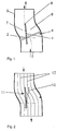
- the closing body 1 is located in the flow channel 3, which continuously decreases in cross section from the inflow 5 to the outflow 6. This results in an accelerated flow, which hinders the formation of separations.
- the arrangement of the virtual axis of rotation perpendicular to and outside the axis of symmetry of the closing body 1 has the effect that the flow channel in the area of the closing body 1 is divided into an area 7 with greater resistance and an area 8 with less resistance.
- the two flows combine at the rear edge of the closing body 1.
- the different speeds lead here to the formation of a fluidized bed 9, which dissolves further downstream into small eddies.
- the free mobility of the closing body 1 prevents the formation of a detachment.
- the flow channel 3 has an S-shaped curved center line. This form of curvature is required to close the flap. If the flow has come to rest at the end of the flow-through phase and the backflow begins, the flow behaves like a frictionless liquid. Boundary layers and speed profiles have not yet developed.
- Fig. 2 shows the arrangement of the streamlines of such a flow.
- the streamlines 10 run through the plane of the closing body 1 and thus have in the initial phase a component 11 perpendicular to the axis of rotation of the closing body 1, which exerts a torque on the closing body.
- the flow thus takes the closing body 1 with it and rotates it a little further into the flow into the position 12, which further increases the entraining effect and the flap quickly comes into the closed position up to the stop 4.
Landscapes
- Health & Medical Sciences (AREA)
- Cardiology (AREA)
- Oral & Maxillofacial Surgery (AREA)
- Transplantation (AREA)
- Engineering & Computer Science (AREA)
- Biomedical Technology (AREA)
- Heart & Thoracic Surgery (AREA)
- Vascular Medicine (AREA)
- Life Sciences & Earth Sciences (AREA)
- Animal Behavior & Ethology (AREA)
- General Health & Medical Sciences (AREA)
- Public Health (AREA)
- Veterinary Medicine (AREA)
- Prostheses (AREA)
- External Artificial Organs (AREA)
Abstract
Die Erfindung betrifft eine mechanische Herzklappe für künstliche Blutpumpen und Konduits. Ein Schließkörper befindet sich in einem Strömungskanal mit einer S-förmig geformten Mittellinie und mit in Stromrichtung abnehmender Querschnittstläche. Der Schließkörper ist in der Form eines Rotationskörpers ausgebildet und ist um einen Zapfen oder um eine virtuelle Achse drehbar, welche außerhalb des Schwerpunktes des Rotationskörpers liegt.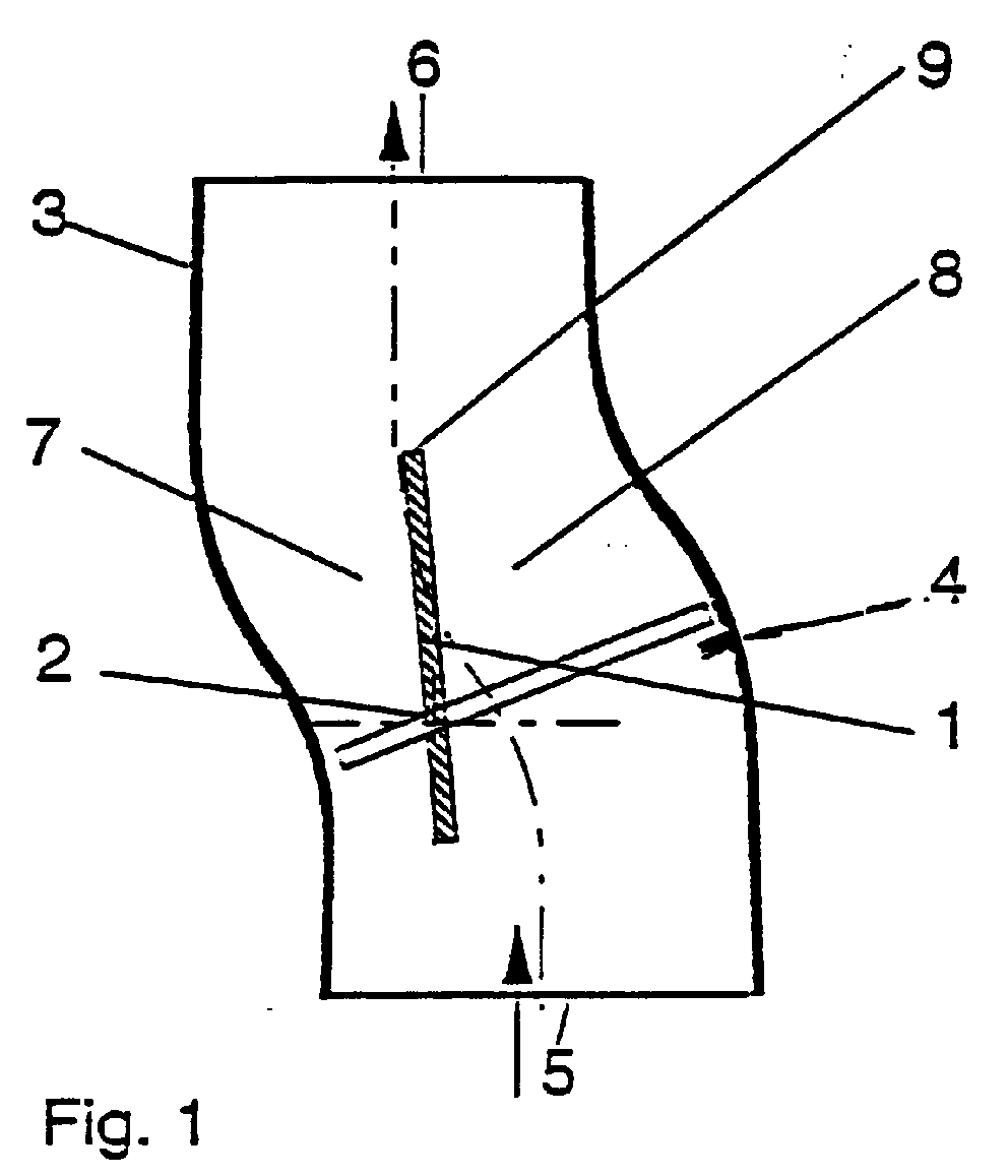
Description
Die Erfindung betrifft eine mechanische Herzklappe für die Anwendung als künstliches Herz oder als Herzunterstützungssystem oder aber für den Einsatz in künstlichen Konduits, wie sie für eine Verbindung der linken Herzkammer mit der Aorta implantiert werden.The invention relates to a mechanical heart valve for use as an artificial heart or as a cardiac support system or for use in artificial conduits, such as those implanted for connecting the left ventricle to the aorta.
Eine künstliche mechanische Herzklappe hat die Aufgabe, den Blutstrom in der einen Richtung freizugeben und in der umgekehrten Richtung Zu verschließen. Dabei soll sie einen möglichst großen freien Querschnitt freigeben, wenn der Druck stromauf größer als stromab ist. In dieser Phase soll der Schließkörper, ein bewegliches Element der mechanischen Herzklappe, der Blutströmung einen möglichst geringen Widerstand bieten. Kehrt sich durch die Wirkung des Herzens dieses Druckverhältnis um, soll die mechanische Herzklappe diesen Querschnitt schnell verschließen, um eine Rückströmung einer größeren Blutmenge zu vermeiden.An artificial mechanical heart valve has the task of releasing the blood flow in one direction and closing it in the opposite direction. It should release the largest possible free cross-section if the pressure upstream is greater than downstream. In this phase, the closing body, a movable element of the mechanical heart valve, should offer the least possible resistance to the blood flow. If this pressure ratio is reversed due to the effect of the heart, the mechanical heart valve should quickly close this cross-section in order to prevent a backflow of a large amount of blood.
Die Wermstoffe, die für den Bau einer solchen mechanischen Herzklappe zur Verfügung stehen, sind den natürlichen Stoffen, aus denen der Körper die blutführenden Elemente aufbaut, weit unterlegen. Die künstlichen Werkstoffe können die Bildung von Blutgerinnseln verursachen, die die Funktion der mechanischen Herzklappe behindern oder auch Blutgefäße weiter stromab verschließen können. Diese Vorgänge werden neben den Werkstoffeigenschaften weiterhin wesentlich auch durch die Blutströmung durch die Herzklappe bestimmt. Besonders nachteilig sind Stagnationsbereiche, in denen das Blut sich nur wenig oder auch zirkulär bewegt. Solche Bereiche sind technisch gesehen Strömungsablösungen und sie entstehen vor allem, wenn sich der Strömungsquerschnitt erweitert oder aber Ausnehmungen, Kanten und Vertiefungen aufweist. Auch in die Strömung hineinragende Elemente wie Schließkörper, Bügel, Achsen oder Stützen sind an ihrer stromab gelegenen Seite mit der Gefahr der Strömungsablösung verbunden.The worms that are available for the construction of such a mechanical heart valve are far inferior to the natural substances from which the body builds the blood-carrying elements. The artificial materials can cause blood clots to form, which can hinder the functioning of the mechanical heart valve or close blood vessels further downstream. In addition to the material properties, these processes are also largely determined by the blood flow through the heart valve. Stagnation areas in which the blood moves only slightly or in a circular manner are particularly disadvantageous. From a technical point of view, such areas are flow separations and they arise above all if the flow cross section widens or if it has recesses, edges and depressions. Elements protruding into the flow, such as closing bodies, brackets, axes or supports, are also at risk on their downstream side connected to the flow separation.
Es sind zahlreiche mechanische Herzklappen bekannt, bei denen versucht wird, Strömungsablösungen durch strömungsgünstig gestaltete Schließkörper zu vermeiden.Numerous mechanical heart valves are known in which an attempt is made to avoid flow separation by means of closing bodies which are designed to be aerodynamically efficient.
Weiterhin sind mechanische Herzklappen bekannt, bei denen sich der Querschnitt im Bereich ihres Halteringes in stromrichtung verringert, damit im Bereich der Zapfenlagerung eine beschleunigte Strömung herrscht und so die Gefahr einer Strömungsablösung verringert wird. Jedoch erstreckt sich der Bereich der beschleunigten Strömung nur auf einen kurzen Bereich und schließt nicht den ganzen Bereich der Herzklappe ein.Furthermore, mechanical heart valves are known in which the cross section in the area of their retaining ring is reduced in the direction of the current, so that an accelerated flow prevails in the area of the pin bearing and thus the risk of flow separation is reduced. However, the area of accelerated flow extends only over a short area and does not include the entire area of the heart valve.
Allen diesen mechanischen Herzklappen gemeinsam ist, daß der Schließkörper während der Durchströmphase durch Anschläge in seiner Winkelstellung fixiert wird. Gewöhnlich ist der Anstellwinkel des Schließkörpers zur Strömung so groß, daß die Strömung auf der einen Seite des Schließkörpers abreißt und damit eine Strömungsablösung auftritt.All these mechanical heart valves have in common that the closing body is fixed in its angular position by stops during the flow-through phase. Usually the angle of attack of the closing body to the flow is so great that the flow breaks off on one side of the closing body and thus a flow separation occurs.
Allen diesen bekannten mechanischen Herzklappen ist weiterhin gemeinsam, daß eine Strömungsablösung an der Hinterkante ihres Halteringes unvermeidlich ist, weil sich an dieser Stelle der Strömungsquerschnitt erweitert. Die Folge ist, daß alle mechanischen Herzklappen, die aus einem nicht optimal blutverträglichen Material gefertigt sind - dies betrifft alle mechanischen Herzklappen - mit einer bestimmten Rate an thromboembolischen Komplikationen verbunden sind, welche dann den Patienten gefährden.All these known mechanical heart valves also have in common that flow separation at the rear edge of their retaining ring is unavoidable because the flow cross section widens at this point. The result is that all mechanical heart valves that are made of a material that is not optimally compatible with the blood - this applies to all mechanical heart valves - are associated with a certain rate of thromboembolic complications, which then endanger the patient.
Diese mechanischen Herzklappen sind für den Ersatz der erkrankten natürlichen Herzen entwickelt worden und auf die dabei vorgefundene Geometrie der natürlichen Strömungkanäle wie zum Beispiel die Aortenwurzel abgestimmt. Bei künstlichen Blutpumpen dagegen ist für die Klappen keine anatomisch bestimmte Geometrie vorgegeben und der Strömungskanal um den Schließkörper kann frei gestaltet werden. Das Gleiche gilt für Konduits, die für eine Verbindung der Herzkammer mit der Aorta klinisch eingesetzt werden.These mechanical heart valves have been developed for the replacement of diseased natural hearts and matched to the geometry of the natural flow channels found here, such as the aortic root. With artificial blood pumps, on the other hand, none is anatomical for the valves certain geometry is specified and the flow channel around the closing body can be designed freely. The same applies to conduits that are used clinically to connect the ventricle to the aorta.
Der Erfindung liegt die Aufgabe zugrunde, die oben erwähnten Nachteile der bisherigen Lösungen zu vermeiden wie beispielsweise die Strömungsablösung und die an sich bekannte Aufgabe auf technisch bessere Weise zu lösen.The invention is based on the object of avoiding the above-mentioned disadvantages of the previous solutions, such as solving the flow and solving the known problem in a technically better way.
Dies wird gemäß der Erfindung dadurch erreicht, daß eine mechanische Herzklappe für künstliche Blutpumpen und Konduits, einen um reale Zapfen oder um eine virtuelle Drehachse drehbaren Schließkörper aufweist, der sich in einem langgestreckten, den gesamten Schließkörper in seiner geöffneten Stellung umschließenden Strömungskanal mit einer S-förmig geformten Mittellinie befindet, wobei der Schließkörper nur durch die Strömung des Blutes betätigbar ist.This is achieved in accordance with the invention in that a mechanical heart valve for artificial blood pumps and conduits has a closing body which can be rotated about real pins or about a virtual axis of rotation and which has an S- in an elongated flow channel which surrounds the entire closing body in its open position. shaped center line is located, the closing body can only be actuated by the flow of blood.
Die Strömung im gesamten Bereich der mechanischen Herzklappe wird damit gemäß der Erfindung so geführt, daß der Querschnitt des Strömungskanals sich stetig verkleinert und nicht erweitert, wobei insbesondere auch der Bereich des Schließkörpers mit eingeschlossen ist. Der scheibenförmige Schließkörper kann dabei nach einer der bekannten und bewährten Weisen durch Bügel oder Vorsprünge und Anschläge gelagert sein.The flow in the entire area of the mechanical heart valve is thus guided according to the invention in such a way that the cross section of the flow channel is continuously reduced and not expanded, the area of the closing body also being included in particular. The disc-shaped closing body can be supported by brackets or projections and stops according to one of the known and proven ways.
Die mit der Erfindung erzielten Vorteile bestehen insbesondere darin, daß die Strömung so geführt wird, daß Strömungsablösungen im ganzen Bereich der mechanischen Herzklappe vermieden werden.The advantages achieved with the invention consist in particular in that the flow is guided in such a way that flow separations in the entire area of the mechanical heart valve are avoided.
Die Erfindung wird anhand der Zeichnungen naher erläutert. Hierbei zeigen:
- FIG.1
- eine schematische Darstellung der mechanische Herzklappe im Längsschnitt;
- FIG.2
- die Darstellung nach
Figur 1, ebenfalls im Längsschnitt, wobei im Bereich der Herzklappe die Stromlinien zu Beginn der Rückstromphase dargestellt sind.
- FIG. 1
- a schematic representation of the mechanical heart valve in longitudinal section;
- FIG. 2
- the representation of Figure 1, also in longitudinal section, the streamlines are shown at the beginning of the reverse flow phase in the heart valve.
Der Schließkörper 1 ist ein flacher Rotationskörper, der etwa im Drittel seines Durchmessers in einem Zapfen gelagert oder durch eine hier nicht näher beschriebene aber im Prinzip bekannte Konstruktion um eine virtuelle Drehachse 2 drehbar gelagert ist. Der Schließkörper 1 hat einen Anschlag 4, der ihn in geschlossenem Zustand an einer weiteren Bewegung hindert. In der offenen Stellung weist der Schließkörper 1 keinen Anschlag auf und kann sich in seiner Winkelstellung somit frei einstellen und der Strömung vollständig anpassen. Der Schließkörper 1 befindet sich im Strömungskanal 3, der in seinem Querschnitt vom Einstrom 5 zum Ausstrom 6 hin stetig abnimmt. Dadurch wird eine beschleunigte Strömung erzielt, welche die Ausbildung von Ablösungen behindert. Die Anordnung der virtuellen Drehachse senkrecht zur und außerhalb der Symmetrieachse des Schließkörpers 1 bewirkt, daß der Strömungskanal im Bereich des Schließkörpers 1 in einen Bereich 7 mit größerem Widerstand und einen Bereich 8 mit geringerem Widerstand unterteilt wird. An der Hinterkante des Schließkörper 1 vereinigen sich die beiden Ströme. Die unterschiedlichen Geschwindigkeiten führen hier zur Bildung einer Wirbelschicht 9, die sich weiter stromabwärts in kleine Wirbel auflöst. Die freie Beweglichkeit des Schließkörpers 1 verhindert jedoch die Bildung einer Ablösung. Weiterhin besitzt der Strömungskanal 3 eine S-förmig gekrümmte Mittellinie. Diese Form der Krümmung ist für das Schließen der Klappe erforderlich. Ist am Ende der Durchströmphase die Strömung zur Ruhe gekommen und beginnt die Rückströmung, so verhält sich die Strömung wie bei einer reibungsfreien Flüssigkeit. Grenzschichten und Geschwindigkeitsprofile haben sich noch nicht ausgebildet.The
Fig. 2 zeigt die Anordnung der Stromlinien einer solchen Strömung. Die Stromlinien 10 laufen durch die Ebene des Schließkörpers 1 und haben in der Anfangsphase damit eine Komponente 11 senkrecht zur Drehachse des Schließkörpers 1, welche ein Drehmoment auf den Schließkörper ausübt. Damit nimmt die Strömung den Schließkörper 1 mit und dreht ihn etwas weiter in die Strömung in die Position 12, wodurch sich die Mitnahmewirkung weiter verstärkt und die Klappe schnell in die geschlossene Position bis zum Anschlag 4 kommt.Fig. 2 shows the arrangement of the streamlines of such a flow. The
Claims (5)
Applications Claiming Priority (2)
| Application Number | Priority Date | Filing Date | Title |
|---|---|---|---|
| DE1996104881 DE19604881A1 (en) | 1996-02-10 | 1996-02-10 | Mechanical prosthetic heart valve |
| DE19604881 | 1996-02-10 |
Publications (3)
| Publication Number | Publication Date |
|---|---|
| EP0809983A2 true EP0809983A2 (en) | 1997-12-03 |
| EP0809983A3 EP0809983A3 (en) | 1998-01-07 |
| EP0809983B1 EP0809983B1 (en) | 2004-04-21 |
Family
ID=7785036
Family Applications (1)
| Application Number | Title | Priority Date | Filing Date |
|---|---|---|---|
| EP97102039A Expired - Lifetime EP0809983B1 (en) | 1996-02-10 | 1997-02-09 | Mechanical heart valve |
Country Status (3)
| Country | Link |
|---|---|
| US (1) | US5980568A (en) |
| EP (1) | EP0809983B1 (en) |
| DE (2) | DE19604881A1 (en) |
Families Citing this family (1)
| Publication number | Priority date | Publication date | Assignee | Title |
|---|---|---|---|---|
| CA2561188A1 (en) * | 2004-03-31 | 2005-10-20 | Med Institute, Inc. | Endoluminal graft with a prosthetic valve |
Family Cites Families (17)
| Publication number | Priority date | Publication date | Assignee | Title |
|---|---|---|---|---|
| US15192A (en) * | 1856-06-24 | Tubular | ||
| US30507A (en) * | 1860-10-23 | Nathaniel m | ||
| US1306391A (en) * | 1918-02-09 | 1919-06-10 | Hippolyte Romanoff | Valve. |
| GB1399750A (en) * | 1972-07-12 | 1975-07-02 | Bradley Ltd G & E | Pump |
| US4021863A (en) * | 1976-09-13 | 1977-05-10 | M-K-V Corporation | Heart valve prosthesis |
| USRE30507E (en) | 1979-03-22 | 1981-02-10 | Heart valve prosthesis | |
| US4546499A (en) * | 1982-12-13 | 1985-10-15 | Possis Medical, Inc. | Method of supplying blood to blood receiving vessels |
| US4597767A (en) * | 1982-12-15 | 1986-07-01 | Andrew Lenkei | Split leaflet heart valve |
| DE3426300A1 (en) * | 1984-07-17 | 1986-01-30 | Doguhan Dr.med. 6000 Frankfurt Baykut | TWO-WAY VALVE AND ITS USE AS A HEART VALVE PROSTHESIS |
| DE3701702C1 (en) * | 1987-01-22 | 1988-07-14 | Braun Melsungen Ag | Heart valve prosthesis |
| FR2612597B1 (en) * | 1987-03-20 | 1989-06-23 | Colon Jean | VALVE HAS AT LEAST ONE TILT SHUTTER IN RELATION TO ELASTIC PIVOTS |
| US4979955A (en) * | 1988-06-06 | 1990-12-25 | Smith Robert M | Power assisted prosthetic heart valve |
| DE3828781A1 (en) * | 1988-08-25 | 1990-03-08 | Braun Melsungen Ag | HEART VALVE PROSTHESIS |
| US5064432A (en) * | 1989-06-30 | 1991-11-12 | Republic Medical Products Inc. | Bicurved leaflet(s) prosthetic heart valve |
| US4950287A (en) * | 1989-06-30 | 1990-08-21 | Republic Medical Products, Inc. | Bicurved leaflet(s) prosthetic heart valve |
| US5522886A (en) * | 1994-07-29 | 1996-06-04 | Milo; Simcha | Heart valve prostheses |
| US5641324A (en) * | 1995-05-16 | 1997-06-24 | Medical Carbon Research Institute, Llc | Prosthetic heart valve |
-
1996
- 1996-02-10 DE DE1996104881 patent/DE19604881A1/en not_active Withdrawn
-
1997
- 1997-02-09 DE DE59711531T patent/DE59711531D1/en not_active Expired - Fee Related
- 1997-02-09 EP EP97102039A patent/EP0809983B1/en not_active Expired - Lifetime
- 1997-02-10 US US08/799,022 patent/US5980568A/en not_active Expired - Fee Related
Also Published As
| Publication number | Publication date |
|---|---|
| EP0809983A3 (en) | 1998-01-07 |
| DE19604881A1 (en) | 1997-08-14 |
| EP0809983B1 (en) | 2004-04-21 |
| US5980568A (en) | 1999-11-09 |
| DE59711531D1 (en) | 2004-05-27 |
Similar Documents
| Publication | Publication Date | Title |
|---|---|---|
| DE3701704C1 (en) | Heart valve prosthesis | |
| DE2742681C3 (en) | Prosthetic closure element to replace the mitral and tricus pldal valve in the human heart | |
| DE69930500T2 (en) | HEART VALVE PROSTHESIS | |
| EP2607712B1 (en) | Pump housing with an interior for holding a pump rotor | |
| DE2819089C2 (en) | ||
| EP0910313B1 (en) | Mitral valve prosthesis | |
| DE69215960T2 (en) | Heart valve prosthesis, especially to replace the aortic valve | |
| DE3701702C1 (en) | Heart valve prosthesis | |
| DE2640246C3 (en) | Prosthetic heart valve | |
| DE2137782A1 (en) | Artificial limb or organ for living beings | |
| DE2149026A1 (en) | Non-traumatic blood pump | |
| DE1916787B2 (en) | Artificial heart valve | |
| DE2056798A1 (en) | Artificial heart valve | |
| EP0355323B1 (en) | Heart valve prosthesis | |
| DE102016106888A1 (en) | air vents | |
| EP0173723B1 (en) | Prosthesis for replacing aortic valves | |
| DE1403545A1 (en) | Cross-flow blower, in which the field of a potential vortex is superimposed on the inside of the runner to guide the throughput flow | |
| DE2612810B2 (en) | Prosthetic heart valve | |
| DE3428015C1 (en) | Supercritical wing profile | |
| EP0809983B1 (en) | Mechanical heart valve | |
| EP0275535A1 (en) | Heart valve prosthesis | |
| DE2608151A1 (en) | VALVE PROSTHESIS WITH FLOW IN ONE DIRECTION | |
| DE2013866C3 (en) | Prosthetic heart valve | |
| DE19627859C1 (en) | Heart valve prosthesis | |
| AT503184A1 (en) | SHOVEL FOR A SHOVEL WHEEL |
Legal Events
| Date | Code | Title | Description |
|---|---|---|---|
| PUAI | Public reference made under article 153(3) epc to a published international application that has entered the european phase |
Free format text: ORIGINAL CODE: 0009012 |
|
| PUAL | Search report despatched |
Free format text: ORIGINAL CODE: 0009013 |
|
| AK | Designated contracting states |
Kind code of ref document: A2 Designated state(s): DE FR IT |
|
| AK | Designated contracting states |
Kind code of ref document: A3 Designated state(s): DE FR IT |
|
| 17P | Request for examination filed |
Effective date: 19980505 |
|
| RAP1 | Party data changed (applicant data changed or rights of an application transferred) |
Owner name: CARDIOBERLIN GMBH |
|
| RIN1 | Information on inventor provided before grant (corrected) |
Inventor name: AFFELD, KLAUS, PROF. DR. ING |
|
| GRAP | Despatch of communication of intention to grant a patent |
Free format text: ORIGINAL CODE: EPIDOSNIGR1 |
|
| GRAS | Grant fee paid |
Free format text: ORIGINAL CODE: EPIDOSNIGR3 |
|
| GRAA | (expected) grant |
Free format text: ORIGINAL CODE: 0009210 |
|
| AK | Designated contracting states |
Kind code of ref document: B1 Designated state(s): DE FR IT |
|
| REF | Corresponds to: |
Ref document number: 59711531 Country of ref document: DE Date of ref document: 20040527 Kind code of ref document: P |
|
| ET | Fr: translation filed | ||
| PG25 | Lapsed in a contracting state [announced via postgrant information from national office to epo] |
Ref country code: IT Free format text: LAPSE BECAUSE OF NON-PAYMENT OF DUE FEES;WARNING: LAPSES OF ITALIAN PATENTS WITH EFFECTIVE DATE BEFORE 2007 MAY HAVE OCCURRED AT ANY TIME BEFORE 2007. THE CORRECT EFFECTIVE DATE MAY BE DIFFERENT FROM THE ONE RECORDED. Effective date: 20050209 |
|
| PLBE | No opposition filed within time limit |
Free format text: ORIGINAL CODE: 0009261 |
|
| STAA | Information on the status of an ep patent application or granted ep patent |
Free format text: STATUS: NO OPPOSITION FILED WITHIN TIME LIMIT |
|
| 26N | No opposition filed |
Effective date: 20050124 |
|
| PG25 | Lapsed in a contracting state [announced via postgrant information from national office to epo] |
Ref country code: FR Free format text: LAPSE BECAUSE OF NON-PAYMENT OF DUE FEES Effective date: 20051031 |
|
| REG | Reference to a national code |
Ref country code: FR Ref legal event code: ST Effective date: 20051031 |
|
| PG25 | Lapsed in a contracting state [announced via postgrant information from national office to epo] |
Ref country code: DE Free format text: LAPSE BECAUSE OF NON-PAYMENT OF DUE FEES Effective date: 20050901 |