EP0809966B1 - Through-flow cell for extracorporeal measurement of blood parameters - Google Patents
Through-flow cell for extracorporeal measurement of blood parameters Download PDFInfo
- Publication number
- EP0809966B1 EP0809966B1 EP97105614A EP97105614A EP0809966B1 EP 0809966 B1 EP0809966 B1 EP 0809966B1 EP 97105614 A EP97105614 A EP 97105614A EP 97105614 A EP97105614 A EP 97105614A EP 0809966 B1 EP0809966 B1 EP 0809966B1
- Authority
- EP
- European Patent Office
- Prior art keywords
- pressure sensor
- flow cell
- sensors
- measuring chamber
- cell according
- Prior art date
- Legal status (The legal status is an assumption and is not a legal conclusion. Google has not performed a legal analysis and makes no representation as to the accuracy of the status listed.)
- Expired - Lifetime
Links
- 239000008280 blood Substances 0.000 title claims description 19
- 210000004369 blood Anatomy 0.000 title claims description 19
- 238000005259 measurement Methods 0.000 title claims description 12
- 238000012545 processing Methods 0.000 claims description 13
- XUIMIQQOPSSXEZ-UHFFFAOYSA-N Silicon Chemical compound [Si] XUIMIQQOPSSXEZ-UHFFFAOYSA-N 0.000 claims description 5
- 229910052710 silicon Inorganic materials 0.000 claims description 5
- 239000010703 silicon Substances 0.000 claims description 5
- 238000013461 design Methods 0.000 claims description 3
- 239000012530 fluid Substances 0.000 claims description 2
- 238000005516 engineering process Methods 0.000 description 13
- 239000004065 semiconductor Substances 0.000 description 10
- 239000003570 air Substances 0.000 description 7
- 230000004872 arterial blood pressure Effects 0.000 description 5
- 239000007788 liquid Substances 0.000 description 4
- 238000004519 manufacturing process Methods 0.000 description 4
- 238000000034 method Methods 0.000 description 4
- 230000036772 blood pressure Effects 0.000 description 3
- 238000009530 blood pressure measurement Methods 0.000 description 3
- 239000012528 membrane Substances 0.000 description 3
- 239000003792 electrolyte Substances 0.000 description 2
- 238000011156 evaluation Methods 0.000 description 2
- 238000012544 monitoring process Methods 0.000 description 2
- 238000007789 sealing Methods 0.000 description 2
- 239000000758 substrate Substances 0.000 description 2
- 239000012080 ambient air Substances 0.000 description 1
- 210000001367 artery Anatomy 0.000 description 1
- 230000015572 biosynthetic process Effects 0.000 description 1
- 239000012482 calibration solution Substances 0.000 description 1
- 239000012876 carrier material Substances 0.000 description 1
- 238000004891 communication Methods 0.000 description 1
- 150000001875 compounds Chemical class 0.000 description 1
- 238000005520 cutting process Methods 0.000 description 1
- 230000001419 dependent effect Effects 0.000 description 1
- 230000005669 field effect Effects 0.000 description 1
- 239000010408 film Substances 0.000 description 1
- 239000003978 infusion fluid Substances 0.000 description 1
- 230000010354 integration Effects 0.000 description 1
- 239000002207 metabolite Substances 0.000 description 1
- 238000005459 micromachining Methods 0.000 description 1
- 239000012487 rinsing solution Substances 0.000 description 1
- 230000008054 signal transmission Effects 0.000 description 1
- 238000003860 storage Methods 0.000 description 1
- 239000000126 substance Substances 0.000 description 1
- 239000010409 thin film Substances 0.000 description 1
- 238000012546 transfer Methods 0.000 description 1
- XLYOFNOQVPJJNP-UHFFFAOYSA-N water Substances O XLYOFNOQVPJJNP-UHFFFAOYSA-N 0.000 description 1
Images
Classifications
-
- G—PHYSICS
- G01—MEASURING; TESTING
- G01L—MEASURING FORCE, STRESS, TORQUE, WORK, MECHANICAL POWER, MECHANICAL EFFICIENCY, OR FLUID PRESSURE
- G01L19/00—Details of, or accessories for, apparatus for measuring steady or quasi-steady pressure of a fluent medium insofar as such details or accessories are not special to particular types of pressure gauges
- G01L19/0092—Pressure sensor associated with other sensors, e.g. for measuring acceleration or temperature
-
- A—HUMAN NECESSITIES
- A61—MEDICAL OR VETERINARY SCIENCE; HYGIENE
- A61B—DIAGNOSIS; SURGERY; IDENTIFICATION
- A61B5/00—Measuring for diagnostic purposes; Identification of persons
- A61B5/02—Detecting, measuring or recording for evaluating the cardiovascular system, e.g. pulse, heart rate, blood pressure or blood flow
- A61B5/021—Measuring pressure in heart or blood vessels
- A61B5/0215—Measuring pressure in heart or blood vessels by means inserted into the body
- A61B5/02158—Measuring pressure in heart or blood vessels by means inserted into the body provided with two or more sensor elements
-
- A—HUMAN NECESSITIES
- A61—MEDICAL OR VETERINARY SCIENCE; HYGIENE
- A61B—DIAGNOSIS; SURGERY; IDENTIFICATION
- A61B5/00—Measuring for diagnostic purposes; Identification of persons
- A61B5/145—Measuring characteristics of blood in vivo, e.g. gas concentration or pH-value ; Measuring characteristics of body fluids or tissues, e.g. interstitial fluid or cerebral tissue
- A61B5/1455—Measuring characteristics of blood in vivo, e.g. gas concentration or pH-value ; Measuring characteristics of body fluids or tissues, e.g. interstitial fluid or cerebral tissue using optical sensors, e.g. spectral photometrical oximeters
- A61B5/14551—Measuring characteristics of blood in vivo, e.g. gas concentration or pH-value ; Measuring characteristics of body fluids or tissues, e.g. interstitial fluid or cerebral tissue using optical sensors, e.g. spectral photometrical oximeters for measuring blood gases
- A61B5/14557—Measuring characteristics of blood in vivo, e.g. gas concentration or pH-value ; Measuring characteristics of body fluids or tissues, e.g. interstitial fluid or cerebral tissue using optical sensors, e.g. spectral photometrical oximeters for measuring blood gases specially adapted to extracorporeal circuits
-
- A—HUMAN NECESSITIES
- A61—MEDICAL OR VETERINARY SCIENCE; HYGIENE
- A61M—DEVICES FOR INTRODUCING MEDIA INTO, OR ONTO, THE BODY; DEVICES FOR TRANSDUCING BODY MEDIA OR FOR TAKING MEDIA FROM THE BODY; DEVICES FOR PRODUCING OR ENDING SLEEP OR STUPOR
- A61M1/00—Suction or pumping devices for medical purposes; Devices for carrying-off, for treatment of, or for carrying-over, body-liquids; Drainage systems
- A61M1/36—Other treatment of blood in a by-pass of the natural circulatory system, e.g. temperature adaptation, irradiation ; Extra-corporeal blood circuits
- A61M1/3621—Extra-corporeal blood circuits
- A61M1/3639—Blood pressure control, pressure transducers specially adapted therefor
-
- A—HUMAN NECESSITIES
- A61—MEDICAL OR VETERINARY SCIENCE; HYGIENE
- A61M—DEVICES FOR INTRODUCING MEDIA INTO, OR ONTO, THE BODY; DEVICES FOR TRANSDUCING BODY MEDIA OR FOR TAKING MEDIA FROM THE BODY; DEVICES FOR PRODUCING OR ENDING SLEEP OR STUPOR
- A61M2205/00—General characteristics of the apparatus
- A61M2205/33—Controlling, regulating or measuring
- A61M2205/3331—Pressure; Flow
- A61M2205/3334—Measuring or controlling the flow rate
Definitions
- the invention relates to a flow cell for extracorporeal Measurement of blood parameters with one in a measuring chamber arranged pressure sensor.
- a flow measuring cell with the features of the preamble of claim 1 is known from PCT Publication WO 92/05449.
- the flow cell includes a first measuring chamber having a plurality of disposed therein electrochemical sensors.
- An inlet opening of the first Measuring chamber is via a liquid connection line connected to a switching unit.
- a liquid conveying device is connected.
- rinsing solution or calibration solution by means of the liquid conveyor sucked through the measuring chamber and then be promoted to a Verschsch.
- the second measuring chamber is via another fluid connection line with the Switching unit connected. In the switching unit is in the Switching states "ready" and "measuring" connect to one Made measuring line, so that in these switch positions a continuous pressure measurement can take place.
- EP-A-0 714 017 are silicon thin film pressure sensors described that are compatible with common in CMOS technology Processes can be produced. Compatible with CMOS manufacturing processes means that in the manufacture of the Sensors needed additional process steps in standard CMOS process steps can be integrated and not to disturb. This technology is also called surface micromechanical technology designated. In addition to the pressure sensor there are still electronic circuits on the same chip integrated monolithically.
- the invention is based on the object, a compact and robust flow cell for extracorporeal measurement of Specify blood parameters with which an easy to handle and interference-sensitive blood monitoring system can be.
- the object is solved by the features of claim 1.
- the output of the same, but inactive Pressure sensor part in the same way as the blood pressure sensor of other factors, such. Temperature, voltages in the carrier material as well as production-related variabilities determined and can be used to correct these disturbances become.
- the patient-near arrangement of the pressure sensor allows a largely unattenuated measurement of the arterial Blood pressure. For reasons of measurement reliability, the must analyzing blood sample through the entire measuring channel and still be further promoted in the second feed channel. The small Cross section of the second feed channel holds this for the measurement the blood parameter required total volume in the flow cell as low as possible.
- An advantageous embodiment is characterized by that in the measuring chamber additionally at least one electrochemical Sensor is arranged.
- the arrangement of one or more electrochemical sensors with the pressure sensor in one Housing simplifies the handling of the sensors and a makes the flow measuring cell insensitive to disturbances. On the other hand This gives the possibility, in addition to an evaluation to arrange in the same housing in which then all Sensors for the determination of blood parameters housed are.
- a further advantageous embodiment is characterized from that outside the measuring chamber arranged an external pressure sensor is for measuring a ruling outside the measuring channel external air pressure.
- the outside pressure sensor is the external air pressure is measured and can then be subtracted from the pressure be with that with the arterial column of blood in Compound pressure sensor is measured. Since in the Measuring chamber arranged pressure sensor a sum of ambient air pressure and arterial blood pressure can be determined by subtraction the arterial blood pressure can be determined.
- the Communication of the external pressure sensor with the surrounding air pressure can be made through a hole in the housing. This hole can be made with a moisture impermeable Be completed membrane, which transmits the air pressure, however Ingress of splashing water, humidity or similar prevented.
- the external pressure sensor comprises an active and an inactive external pressure sensor part, wherein the inactive external pressure sensor part identical is formed with the active external pressure sensor part and the inactive external pressure sensor part by a rigid cover from external air pressure is isolated. So can the measured values of the external pressure sensor are freed from interference.
- An inexpensive and compact flow cell can be build up according to a further advantageous embodiment, by the pressure sensor (s) with first signal processing components are connected and the signal processing components with the pressure sensor or the pressure sensors monolithically integrated on a chip.
- the signal processing components can e.g. with CMOS technology and the Pressure sensors with CMOS-compatible surface micromechanics technology getting produced.
- a particularly compact flow cell which thus also for Measuring only a small volume of blood needed, can then be build up, if according to another, particularly advantageous Design all sensors monolithically integrated on a chip are.
- the sensor associated signal processing components on the Chip monolithically integrated. This is on the one hand the susceptibility the flow cell with the sensors on reduced, on the other hand, the measurement signal in a störunmuse Form to be transformed to transfer.
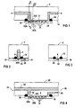
- the two-way flow cell shown in Fig. 1 is used for extracorporeal measurement of chemical and physical blood parameters.
- a support block 2 are Feeding channels 4 and 6 introduced, each to one end lead a formed as a measuring channel 8 measuring chamber.
- the feed channels 4, 6 are at the other end each with connection means connected for hoses or catheters.
- Connection means are common in medical technology or releasable connecting elements into consideration; you are in Fig. 1 but not shown.
- the first feed channel 4 is intended for connection of the two-way flow cell an arterial catheter.
- the second supply channel 6 is under provided otherwise for connecting the two-way flow cell to a pump for delivering a blood sample from the Artery to the measuring channel 8.
- the feed channels 4, 6 extend initially in the longitudinal direction in the support block 2, they then turn to a side surface 14 and open in there the measuring channel 8.
- the feed channels 4, 6 bend at right angles towards the side surface 14 down.
- the cross section of the feed channel 4 is so large that the arterial Blood pressure are passed almost unattenuated to the measuring channel 8 can.
- the volume of the measuring channel 8 and the cross section the second feed channel 6 as small as possible, around the required total sample volume in the flow cell to be kept as low as possible.
- a wall of the Measuring channel 8 is formed by a silicon semiconductor chip 16, which at a distance which determines the height of the measuring channel 8, is arranged from the side surface 14.
- a circumferential Sealing ring 18 seals the area between the semiconductor chip 16 and the support block 2 from. The sealing ring 18 limited thus the measuring channel 8 side and the mouths of the feed channels 4 and 6 in the side surface 14th
- the semiconductor chip 16 On the semiconductor chip 16 are on the side of the measuring channel 8 limited, all sensors integrated. In the Extension of the feed channel 4 is initially a pressure sensor 20 arranged. In the course of the measuring channel 8 are on the semiconductor chip 16 more sensors 22 to measure more Blood parameters, such. Blood gas levels, electrolyte and metabolite concentrations as well as temperature sensors and possibly flow sensors arranged.
- the electrochemical sensors are implemented in thin and thick film technology, which is pressure sensor executed in surface micromechanical technology. Also integrated - preferably in CMOS technology - on the Semiconductor chip 16 is a signal processing circuit associated with the sensors 24.
- the signal processing circuit 24 includes analog-to-digital converters that digitize the measurement signal, an interference-insensitive signal transmission from the chip 16 to enable further electronic evaluation circuits.
- the pressure sensor comprises both an active pressure sensor part 20A, which outputs a pressure-dependent measurement signal, as well a structurally identical inactive pressure sensor part 20B, by a rigid cover 20C of the prevailing in the measuring channel 8 Pressure is isolated.
- the output signal of the same, however Inactive pressure sensor part is the same as the Output signal of the active pressure sensor part of disturbing Influencing variables, such as B. temperature, stresses in the substrate and manufacturing tolerances, determined and can be used to correct these disturbances.
- Fig. 2 shows in a sectional view along an in Fig. 1 as II designated cutting plane the first feed channel 4, in its extension, the active pressure sensor part 20A is arranged on the semiconductor chip 16.
- Pressure sensor part 20A is still on the semiconductor chip 16
- External pressure sensor 26 integrated to measure an outside the measuring channel 8 prevailing external air pressure.
- the external pressure sensor 26 also includes as the pressure sensor in the measuring channel 8 an active external pressure sensor part and an inactive one External pressure sensor part for compensation of disturbing influencing variables.
- the external pressure sensor 26 may communicate with the environment moisture impermeable membrane, however, the Air pressure transmits, be separated.
- the blood pressure value of the patient then results in principle first by the pressure measurements freed from disturbing influences the active pressure sensor part 20A and the outside pressure sensor 26 be formed.
- the pressure measurement values free from interferences arise z. B. from a difference, wherein the measured value of the active pressure sensor part 20A, the value of the inactive Pressure sensor part 20B is subtracted.
- the blood pressure value itself one obtains then by another difference formation, by from the possibly freed from interference Bluttikmeßwert the possibly exempt from disturbing atmospheric external pressure is deducted. At least part of this signal processing is integrated by on the semiconductor chip 16 electronic signal processing circuits performed.
- the sectional view in Fig. 3 along the sectional plane III shows in particular the cross section of the measuring channel 8, which in essentially by the distance of the semiconductor chip 16 from Carrier block 2 and the size of the other sensors 22 determined is.
- the three-way flow cell shown in section in FIG. 4 uses the same semiconductor chip 16 as the two-way flow cell According to Fig. 1, only the liquid-conducting Channels are changed.
- a support block 30 is a straight flow channel 32 with a large cross-section incorporated in the opposite left and right sides 34 and 36, respectively.
- the estuary in the left Page 34 is for connecting the arterial indwelling catheter formed while the mouth in the right side 36 for Connection of a storage container for an infusion solution with a corresponding conveyor is provided.
- a branch 38 leads to the measuring channel 8.
- the cross section of the flow channel 32 is at least as large as the cross section of the branch 38, the cross section the branch 38 is sufficiently large, so that the measuring arterial blood pressure unattenuated to the pressure sensor 20 can be directed.
- the part of the flow channel 32 of the left side 34 to the mouth of the branch 38 and then up to the measuring channel 8 corresponds to the first feed channel. 4 the two-way flow cell in Fig. 1.
- a connecting channel 40 is guided, the also in the right side 36 opens.
- the connection channel 40 is provided for connecting a blood conveyor, taken with the blood samples and to the sensors 20A and 22 can be pumped in the measuring channel 8, it corresponds the second supply channel 6 of the two-way flow cell in Fig. 1.
Landscapes
- Health & Medical Sciences (AREA)
- Life Sciences & Earth Sciences (AREA)
- Physics & Mathematics (AREA)
- Heart & Thoracic Surgery (AREA)
- Biomedical Technology (AREA)
- Animal Behavior & Ethology (AREA)
- Vascular Medicine (AREA)
- Veterinary Medicine (AREA)
- Public Health (AREA)
- General Health & Medical Sciences (AREA)
- Cardiology (AREA)
- Engineering & Computer Science (AREA)
- Pathology (AREA)
- General Physics & Mathematics (AREA)
- Medical Informatics (AREA)
- Molecular Biology (AREA)
- Surgery (AREA)
- Chemical & Material Sciences (AREA)
- Biophysics (AREA)
- Analytical Chemistry (AREA)
- Physiology (AREA)
- Spectroscopy & Molecular Physics (AREA)
- Optics & Photonics (AREA)
- Anesthesiology (AREA)
- Hematology (AREA)
- Measuring Pulse, Heart Rate, Blood Pressure Or Blood Flow (AREA)
- External Artificial Organs (AREA)
Description
Die Erfindung betrifft eine Durchflußmeßzelle zur extrakorporalen Messung von Blutparametern mit einem in einer Meßkammer angeordneten Drucksensor.The invention relates to a flow cell for extracorporeal Measurement of blood parameters with one in a measuring chamber arranged pressure sensor.
Eine Durchflußmeßzelle mit den Merkmalen des Oberbegriffs des Anspruchs 1 ist aus der PCT-Veröffentlichung WO 92/05449 bekannt. Die Durchflußmeßzelle umfaßt eine erste Meßkammer mit mehreren darin angeordneten elektrochemischen Sensoren. Eine Einlaßöffnung der ersten Meßkammer ist über eine Flüssigkeitsverbindungsleitung mit einer Schalteinheit verbunden. An einer Auslaßöffnung der ersten Meßkammer ist eine Flüssigkeitsfördereinrichtung angeschlossen. Je nach Schaltstellung der Schalteinheit können Meßflüssigkeit, Spüllösung oder Eichlösung mittels der Flüssigkeitsfördereinrichtung durch die Meßkammer hindurchgesaugt und dann in einen Verwurf befördert werden. Getrennt von der ersten Meßkammer ist ein Drucksensor in einer zweiten Meßkammer der Durchflußmeßzelle angeordnet. Die zweite Meßkammer ist über eine weitere Flüssigkeitsverbindungsleitung mit der Schalteinheit verbunden. In der Schalteinheit wird in den Schaltzuständen "Bereit" und "Messen" eine Verbindung zu einer Meßleitung hergestellt, so daß in diesen Schaltstellungen eine kontinuierliche Druckmessung erfolgen kann.A flow measuring cell with the features of the preamble of claim 1 is known from PCT Publication WO 92/05449. The flow cell includes a first measuring chamber having a plurality of disposed therein electrochemical sensors. An inlet opening of the first Measuring chamber is via a liquid connection line connected to a switching unit. At an outlet of the first measuring chamber, a liquid conveying device is connected. Depending on the switching position of the switching unit can Measuring liquid, rinsing solution or calibration solution by means of the liquid conveyor sucked through the measuring chamber and then be promoted to a Verwurf. Separated from the first measuring chamber is a pressure sensor in a second measuring chamber arranged the flow cell. The second measuring chamber is via another fluid connection line with the Switching unit connected. In the switching unit is in the Switching states "ready" and "measuring" connect to one Made measuring line, so that in these switch positions a continuous pressure measurement can take place.
Eine weitere Durchflußmeßzelle zur extrakorporalen Messung von mehreren elektrochemisch gemessenen Blutparametern, wie z. B. pH-, pO2-, pCO2-Wert und Elektrolyt-Konzentration, ist in dem US-Patent 4,841,974 beschrieben. Sie wird an einen arteriellen Dauerkatheter angeschlossen. Die Sensoren sind in der Durchflußmeßzelle in einer Wandung eines Meßkanals angeordnet. Die Sensoren selbst sind als ionensensitive Feldeffekt-Transistoren ausgebildet, die gemeinsam auf einem Siliziumchip integriert sind. Dabei dient als Steuerelektrode eine Membran, die eine Grenzfläche zum Meßmedium, also zum entnommmenen Blut, bildet. Eine zugeordnete Auswerteelektronik ist ebenfalls auf dem Chip integriert und bildet eine Baueinheit mit den Sensoren. Der Aufbau des Chips ist auch beschrieben in dem Artikel von W. Gumbrecht, D. Peters, W. Schelter, W. Erhardt, J. Henkel, J. Steil und U. Sykora: "Integrated pO2, pCO2, pH Sensor System for Online Blood Monitoring", Sensors and Actuators B, 18-19 (1994), pp. 704-708.Another flow cell for extracorporeal measurement of several electrochemically measured blood parameters, such. PH, pO 2 , pCO 2 and electrolyte concentration is described in U.S. Patent 4,841,974. It is connected to an arterial permanent catheter. The sensors are arranged in the flow measuring cell in a wall of a measuring channel. The sensors themselves are designed as ion-sensitive field-effect transistors, which are integrated together on a silicon chip. In this case serves as a control electrode, a membrane which forms an interface to the measuring medium, that is, to the ummenmenen blood. An associated transmitter is also integrated on the chip and forms a unit with the sensors. The structure of the chip is also described in the article by W. Gumbrecht, D. Peters, W. Schelter, W. Erhardt, J. Henkel, J. Steil and U. Sykora: "Integrated pO 2 , pCO 2 , pH Sensor System for Online Blood Monitoring, Sensors and Actuators B, 18-19 (1994), pp. 704-708.
In der EP-A-0 714 017 sind Silizium-Dünnfilm-Drucksensoren beschrieben, die kompatibel mit in der CMOS-Technologie üblichen Prozessen hergestellt werden können. Kompatibel zu CMOS-Herstellprozessen bedeutet, daß die bei der Herstellung des Sensors benötigten zusätzlichen Prozeßschritte in Standard-CMOS-Prozeßschritte eingebunden werden können und diese nicht stören. Diese Technologie wird auch als Oberflächen-Mikromechanik-Technologie bezeichnet. Zusätzlich zu dem Drucksensor sind dort auf demselben Chip noch elektronische Schaltungen monolithisch integriert.In EP-A-0 714 017 are silicon thin film pressure sensors described that are compatible with common in CMOS technology Processes can be produced. Compatible with CMOS manufacturing processes means that in the manufacture of the Sensors needed additional process steps in standard CMOS process steps can be integrated and not to disturb. This technology is also called surface micromechanical technology designated. In addition to the pressure sensor there are still electronic circuits on the same chip integrated monolithically.
In der US 4,625,560 ist ein kapazitiver digitaler Druckwandler in Form eines integrierten Schaltkreises beschrieben. Dieser Druckwandler umfasst einen aktiven und einen passiven Wandlerteil. Mit Hilfe des passiven Wandlerteils wird ein störender Einfluss der Umwelt, wie elektrisches, thermisches, inhärentes Rauschen usw., auf das Ausgangssignal kompensiert.In US 4,625,560 is a capacitive digital pressure transducer described in the form of an integrated circuit. This pressure transducer includes one active and one passive Converting part. With the help of the passive converter part is a disturbing influence of the environment, such as electrical, thermal, inherent noise, etc., compensated for the output signal.
Demgegenüber steht eine zur Oberflächen-Mikromechanik verwandte Technologie, die auch als Bulk-Mikromechanik-Technologie bezeichnet wird. Dabei werden die Sensoren wesentlich tiefer in das Silizium-Trägermaterial eingeätzt als bei der Oberflächen-Mikromechanik-Technologie.In contrast, one related to surface micromechanics Technology, also called bulk micromechanics technology referred to as. The sensors are essential etched deeper into the silicon substrate than at the Surface micromachining technology.
Der Erfindung liegt nun die Aufgabe zugrunde, eine kompakte und robuste Durchflußmeßzelle zur extrakorporalen Messung von Blutparametern anzugeben, mit der ein einfach handhabbares und störungsempfindliches Blutmonitoring-System aufgebaut werden kann.The invention is based on the object, a compact and robust flow cell for extracorporeal measurement of Specify blood parameters with which an easy to handle and interference-sensitive blood monitoring system can be.
Die Aufgabe wird durch die Merkmale des Anspruchs 1 gelöst. Dabei ist das Ausgangssignal des baugleichen, aber inaktiven Drucksensorteils in gleicher Weise wie der Blutdrucksensor von weiteren Einflußgrößen, wie z. B. Temperatur, Spannungen im Trägermaterial sowie herstellungsbedingte Variabilitäten bestimmt und kann zur Korrektur dieser Störeinflüsse herangezogen werden. Die patientennahe Anordnung des Drucksensors ermöglicht eine weitgehend ungedämpfte Messung des arteriellen Blutdruckes. Aus Gründen der Meßsicherheit muß die zu analysierende Blutprobe durch den gesamten Meßkanal und noch weiter in den zweiten Zuführkanal gefördert werden. Der kleine Querschnitt des zweiten Zuführkanals hält das zur Messung der Blutparameter benötigte Gesamtvolumen in der Durchflußmeßzelle so gering wie möglich.The object is solved by the features of claim 1. Here is the output of the same, but inactive Pressure sensor part in the same way as the blood pressure sensor of other factors, such. Temperature, voltages in the carrier material as well as production-related variabilities determined and can be used to correct these disturbances become. The patient-near arrangement of the pressure sensor allows a largely unattenuated measurement of the arterial Blood pressure. For reasons of measurement reliability, the must analyzing blood sample through the entire measuring channel and still be further promoted in the second feed channel. The small Cross section of the second feed channel holds this for the measurement the blood parameter required total volume in the flow cell as low as possible.
Eine vorteilhafte Ausgestaltung zeichnet sich dadurch aus, daß in der Meßkammer zusätzlich mindestens ein elektrochemischer Sensor angeordnet ist. Die Anordnung eines oder mehrerer elektrochemischer Sensoren mit dem Drucksensor in einem Gehäuse vereinfacht zum einen die Handhabung der Sensoren und macht die Durchflußmeßzelle störunempfindlich. Zum anderen ist dadurch die Möglichkeit gegeben, zusätzlich eine Auswerteelektronik in demselben Gehäuse anzuordnen, in dem dann alle Sensoren zur Bestimmung von Blutparametern untergebracht sind.An advantageous embodiment is characterized by that in the measuring chamber additionally at least one electrochemical Sensor is arranged. The arrangement of one or more electrochemical sensors with the pressure sensor in one Housing simplifies the handling of the sensors and a makes the flow measuring cell insensitive to disturbances. On the other hand This gives the possibility, in addition to an evaluation to arrange in the same housing in which then all Sensors for the determination of blood parameters housed are.
Eine weitere vorteilhafte Ausgestaltung zeichnet sich dadurch aus, daß außerhalb der Meßkammer ein Außendrucksensor angeordnet ist zur Messung eines außerhalb des Meßkanals herrschenden äußeren Luftdrucks. Mit dem Außendrucksensor wird der äußere Luftdruck gemessen und kann dann von dem Druck abgezogen werden, der mit dem mit der arteriellen Blutsäule in Verbindung stehenden Drucksensor gemessen wird. Da der in der Meßkammer angeordnete Drucksensor eine Summe von Umgebungsluftdruck und arteriellem Blutdruck mißt, kann durch Differenzbildung der arterielle Blutdruck bestimmt werden. Die Kommunikation des Außendrucksensors mit dem umgebenden Luftdruck kann durch eine Bohrung im Gehäuse hergestellt werden. Diese Bohrung kann mit einer feuchtigkeitsundurchlässigen Membran abgeschlossen sein, die den Luftdruck überträgt, jedoch ein Eindringen von Spritzwasser, Luftfeuchtigkeit oder ähnliches verhindert.A further advantageous embodiment is characterized from that outside the measuring chamber arranged an external pressure sensor is for measuring a ruling outside the measuring channel external air pressure. With the outside pressure sensor is the external air pressure is measured and can then be subtracted from the pressure be with that with the arterial column of blood in Compound pressure sensor is measured. Since in the Measuring chamber arranged pressure sensor a sum of ambient air pressure and arterial blood pressure can be determined by subtraction the arterial blood pressure can be determined. The Communication of the external pressure sensor with the surrounding air pressure can be made through a hole in the housing. This hole can be made with a moisture impermeable Be completed membrane, which transmits the air pressure, however Ingress of splashing water, humidity or similar prevented.
Bei einer weiteren vorteilhaften Ausgestaltung umfaßt der Außendrucksensor einen aktiven und einen inaktiven Außendrucksensorteil, wobei der inaktive Außendrucksensorteil baugleich mit dem aktiven Außendrucksensorteil ausgebildet ist und der inaktive Außendrucksensorteil durch eine steife Abdeckung vom äußeren Luftdruck isoliert ist. So können auch die Meßwerte des Außendrucksensors von Störeinflüssen befreit werden.In a further advantageous embodiment, the external pressure sensor comprises an active and an inactive external pressure sensor part, wherein the inactive external pressure sensor part identical is formed with the active external pressure sensor part and the inactive external pressure sensor part by a rigid cover from external air pressure is isolated. So can the measured values of the external pressure sensor are freed from interference.
Eine kostengünstige und kompakte Durchflußmeßzelle läßt sich gemäß einer weiteren vorteilhaften Ausgestaltung aufbauen, indem der Drucksensor bzw. die Drucksensoren mit ersten Signalverarbeitungsbauteilen verbunden sind und die Signalverarbeitungsbauteile mit dem Drucksensor bzw. den Drucksensoren monolithisch auf einem Chip integriert sind. Die Signalverarbeitungsbauteile können z.B. mit CMOS-Technologie und die Drucksensoren mit CMOS-kompatibler Oberflächen-Mikromechanik-Technologie hergestellt werden. An inexpensive and compact flow cell can be build up according to a further advantageous embodiment, by the pressure sensor (s) with first signal processing components are connected and the signal processing components with the pressure sensor or the pressure sensors monolithically integrated on a chip. The signal processing components can e.g. with CMOS technology and the Pressure sensors with CMOS-compatible surface micromechanics technology getting produced.
Eine besonders kompakte Durchflußmeßzelle, die damit auch zum Messen nur ein geringes Blutvolumen benötigt, läßt sich dann aufbauen, wenn gemäß einer weiteren, besonders vorteilhaften Ausgestaltung alle Sensoren monolithisch auf einem Chip integriert sind. Die heute zur Verfügung stehende Oberflächen-Mikromechanik-Technologie erlaubt unter Einsatz von CMOS-kompatiblen Prozeßschritten die monolithische Integration aller Sensoren.A particularly compact flow cell, which thus also for Measuring only a small volume of blood needed, can then be build up, if according to another, particularly advantageous Design all sensors monolithically integrated on a chip are. The surface micromechanics technology available today allowed using CMOS compatible Process steps the monolithic integration of all Sensors.
Bei einer weiteren vorteilhaften Ausgestaltung sind auch die den Sensoren zugeordneten Signalverarbeitungsbauteile auf dem Chip monolithisch integriert. Damit wird zum einen die Störanfälligkeit der Durchflußmeßzelle mit den Sensoren weiter verringert, zum anderen kann das Meßsignal in eine störunempfindliche Form zum Übertragen umgeformt werden.In a further advantageous embodiment, the the sensor associated signal processing components on the Chip monolithically integrated. This is on the one hand the susceptibility the flow cell with the sensors on reduced, on the other hand, the measurement signal in a störunempfindliche Form to be transformed to transfer.
Die Erfindung wird im folgenden anhand von vier Figuren erläutert. Es zeigen:
- Fig. 1
- in einer schematischen Schnittdarstellung eine Zwei weg-Durchflußmeßzelle mit Chemosensoren und einem Drucksensor,
- Fig. 2
- eine Schnittdarstellung der Zweiweg-Durchflußmeßzelle nach Fig. 1 in einer Ebene II,
- Fig. 3
- eine Schnittdarstellung der Zweiweg-Durchflußmeßzelle nach Fig. 1 in der Ebene III und
- Fig. 4
- eine schematische Schittdarstellung einer Dreiweg-Durchflußmeßzelle mit Chemosensoren und einem Druck sensor.
- Fig. 1
- in a schematic sectional view of a two-way flow cell with chemosensors and a pressure sensor,
- Fig. 2
- 1 is a sectional view of the two-way flow measuring cell according to FIG. 1 in a plane II,
- Fig. 3
- a sectional view of the two-way flow measuring cell of Fig. 1 in the plane III and
- Fig. 4
- a schematic Schitt representation of a three-way flow cell with chemosensors and a pressure sensor.
Die in Fig. 1 dargestellte Zweiweg-Durchflußmeßzelle wird
eingesetzt zur extrakorporalen Messung von chemischen und
physikalischen Blutparametern. In einem Trägerblock 2 sind
Zuführkanäle 4 und 6 eingebracht, die jeweils zu einem Ende
einer als Meßkanal 8 ausgebildeten Meßkammer führen. Die Zuführkanäle
4, 6 sind am anderem Ende jeweils mit Anschlußmitteln
für Schlauchleitungen oder auch Katheter verbunden. Als
Anschlußmittel kommen in der Medizintechnik übliche feste
oder auch lösbare Verbindungselemente in Betracht; sie sind
in Fig. 1 jedoch nicht dargestellt. Der erste Zuführkanal 4
ist vorgesehen zum Anschluß der Zweiweg-Durchflußmeßzelle an
einen arteriellen Katheter. Der zweite Zuführkanal 6 ist unter
anderem vorgesehen zum Anschluß der Zweiweg-Durchflußmeßzelle
an eine Pumpe zum Fördern einer Blutprobe aus der
Arterie zum Meßkanal 8. Die Zuführkanäle 4, 6 erstrecken sich
zunächst in Längsrichtung in den Trägerblock 2 hinein, sie
biegen dann zu einer Seitenfläche 14 hin und münden dort in
den Meßkanal 8. Hier biegen die Zuführkanäle 4, 6 rechtwinklig
zu der Seitenfläche 14 hin ab. Der Querschnitt des Zuführkanals
4 ist so groß ausgebildet, daß der arterielle
Blutdruck nahezu ungedämpft zum Meßkanal 8 geleitet werden
kann. Dagegen ist das Volumen des Meßkanals 8 und der Querschnitt
des zweiten Zuführkanals 6 möglichst klein ausgebildet,
um das benötigte Gesamtprobenvolumen in der Durchflußmeßzelle
so gering wie möglich zu halten. Eine Wandung des
Meßkanals 8 wird gebildet von einem Silizium-Halbleiterchip
16, das in einem Abstand, der die Höhe des Meßkanals 8 bestimmt,
von der Seitenfläche 14 angeordnet ist. Ein umlaufender
Dichtring 18 dichtet den Bereich zwischen dem Halbleiterchip
16 und dem Trägerblock 2 ab. Der Dichtring 18 begrenzt
somit den Meßkanal 8 seitlich sowie die Mündungen der Zuführkanäle
4 und 6 in der Seitenfläche 14.The two-way flow cell shown in Fig. 1 is
used for extracorporeal measurement of chemical and
physical blood parameters. In a
Auf dem Halbleiterchip 16 sind auf der Seite, die den Meßkanal
8 begrenzt, alle Sensoren integriert aufgebracht. In der
Verlängerung des Zuführkanals 4 ist zunächst ein Drucksensor
20 angeordnet. Im Verlauf des Meßkanals 8 sind auf dem Halbleiterchip
16 weitere Sensoren 22 zur Messung von weiteren
Blutparametern, wie z. B. Blutgaswerte, Elektrolyt- und Metabolit-Konzentrationen
sowie Temperatursensoren und ggf. Strömungssensoren
angeordnet. Die elektrochemischen Sensoren sind
in Dünn- und Dickfilmtechnik ausgeführt, der Drucksensor ist
in Oberflächen-Mikromechanik-Technologie ausgeführt. Ebenfalls
integriert - vorzugsweise in CMOS-Technologie - auf dem
Halbleiterchip 16 ist eine zu den Sensoren gehörende Signalverarbeitungsschaltung
24. Die Signalverarbeitungsschaltung
24 umfaßt Analog-Digitalwandler, die das Meßsignal digitalisieren,
um eine störunempfindliche Signalübertragung vom Chip
16 zu weiteren elektronischen Auswertungsschaltungen zu ermöglichen.On the
Der Drucksensor umfaßt sowohl einen aktiven Drucksensorteil
20A, der ein vom Druck abhängiges Meßsignal abgibt, wie auch
einen baugleichen inaktiven Drucksensorteil 20B, der durch
eine steife Abdeckung 20C von dem im Meßkanal 8 herrschenden
Druck isoliert ist. Das Ausgangssignal des baugleichen, jedoch
inaktiven Drucksensorteils ist gleichermaßen wie das
Ausgangssignal des aktiven Drucksensorteils von störenden
Einflußgrößen, wie z. B. Temperatur, Verspannungen im Trägermaterial
und herstellungsbedingte Toleranzen, bestimmt und
kann zur Korrektur dieser Störeinflüsse herangezogen werden.The pressure sensor comprises both an active
Fig. 2 zeigt in einer Schnittdarstellung entlang einer in
Fig. 1 als II bezeichneten Schnittebene den ersten Zuführkanal
4, in dessen Verlängerung der aktive Drucksensorteil 20A
auf dem Halbleiterchip 16 angeordnet ist. Zusätzlich zum
Drucksensorteil 20A ist auf dem Halbleiterchip 16 noch ein
Außendrucksensor 26 integriert zur Messung eines außerhalb
des Meßkanals 8 herrschenden äußeren Luftdrucks. Der Außendrucksensor
26 umfaßt ebenfalls wie der Drucksensor im Meßkanal
8 einen aktiven Außendrucksensorteil und einen inaktiven
Außendrucksensorteil zur Kompensation von störenden Einflußgrößen.
Der Außendrucksensor 26 kann von der Umgebung mit einer
feuchtigkeitsundurchlässigen Membran, die jedoch den
Luftdruck überträgt, getrennt sein.Fig. 2 shows in a sectional view along an in
Fig. 1 as II designated cutting plane the first feed channel
4, in its extension, the active
Der Blutdruckwert des Patienten ergibt sich dann prinzipiell,
indem zunächst die von Störeinflüssen befreiten Druckmeßwerte
des aktiven Drucksensorteils 20A und des Außendrucksensors 26
gebildet werden. Die von Störeinflüssen freien Druckmeßwerte
ergeben sich z. B. aus einer Differenzbildung, wobei vom Meßwert
des aktiven Drucksensorteils 20A der Wert des inaktiven
Drucksensorteils 20B abgezogen wird. Den Blutdruckwert selbst
erhält man dann durch eine weitere Differenzbildung, indem
von dem ggf. von Störeinflüssen befreiten Blutdruckmeßwert
der ggf. von Störeinflüssen befreite atmosphärische Außendruck
abgezogen wird. Zumindest ein Teil dieser Signalverarbeitung
wird durch auf dem Halbleiterchip 16 integrierte
elektronische Signalverarbeitungsschaltkreise durchgeführt.The blood pressure value of the patient then results in principle
first by the pressure measurements freed from disturbing influences
the active
Die Schnittdarstellung in Fig. 3 entlang der Schnittebene III
zeigt insbesondere den Querschnitt des Meßkanals 8, der im
wesentlichen durch den Abstand des Halbleiterchips 16 vom
Trägerblock 2 und der Größe der weiteren Sensoren 22 bestimmt
ist.The sectional view in Fig. 3 along the sectional plane III
shows in particular the cross section of the measuring
Die in Fig. 4 im Schnitt dargestellte Dreiweg-Durchflußmeßzelle
verwendet denselben Halbleiterchip 16 wie die Zweiweg-Durchflußzelle
nach Fig. 1, lediglich die flüssigkeitsführenden
Kanäle sind verändert. In einen Trägerblock 30 ist ein
gerade verlaufender Durchflußkanal 32 mit einem großen Querschnitt
eingearbeitet, der in den gegenüberliegenden linken
und rechten Seiten 34 bzw. 36 mündet. Die Mündung in der linken
Seite 34 ist zum Anschluß des arteriellen Dauerkatheters
ausgebildet, während die Mündung in der rechten Seite 36 zum
Anschluß eines Vorratsbehälters für eine Infusionslösung mit
einer dazugehörigen Fördereinrichtung vorgesehen ist.The three-way flow cell shown in section in FIG. 4
uses the
Vom Durchflußkanal 32 führt eine Abzweigung 38 zum Meßkanal
8. Der Querschnitt des Durchflußkanals 32 ist mindestens so
groß wie der Querschnitt der Abzweigung 38, wobei der Querschnitt
der Abzweigung 38 ausreichend groß ist, damit der zu
messende arterielle Blutdruck ungedämpft bis zum Drucksensor
20 geleitet werden kann. Der Teil des Durchflußkanals 32 von
der linken Seite 34 bis zur Mündung der Abzweigung 38 und
dann bis zum Meßkanal 8 entspricht dem ersten Zuführkanal 4
der Zweiweg-Durchflußmeßzelle in Fig. 1. An das andere Ende
des Meßkanals 8 ist ein Verbindungskanal 40 geführt, der
ebenfalls in der rechten Seite 36 mündet. Der Verbindungskanal
40 ist vorgesehen zum Anschluß einer Blutfördereinrichtung,
mit der Blutproben entnommen und zu den Sensoren
20A und 22 im Meßkanal 8 gepumpt werden können, er entspricht
dem zweiten Zuführkanal 6 der Zweiweg-Durchflußmeßzelle in
Fig. 1.From the
Claims (9)
- Through-flow cell for extra-corporeal measurement of blood parameters comprising a pressure sensor (20) arranged in a measuring chamber (8),
characterised in that the pressure sensor (20) has an active and an inactive pressure sensor component (20A or 20B), that the inactive pressure sensor component (20B) is identical in design to the active pressure sensor component (20A), that the inactive pressure sensor component (20B) is isolated from the pressure that is prevalent in the measuring chamber (8) by a rigid cover, and having a first feed channel (4; 32, 38) which is connected to a first end of the measuring chamber (8), the first feed channel (4; 32, 38) being provided for connection of a catheter;
that the pressure sensor (20) is arranged at the first end of the measuring chamber (8), and
that a second feed channel (6; 40) is connected to a second end of the measuring chamber (8),
that the second feed channel (6; 40) is provided for the connection of a fluid transport device,
that the first and the second feed channels (4; 32, 38 and 6; 40 respectively) have a first and a second cross section respectively and that the first cross section is designed to be larger than the second cross section. - Through-flow cell according to Claim 1,
characterized in that at least one electrochemical sensor (22) is additionally arranged in the measuring chamber (8). - Through-flow cell according to Claim 1 or 2,
characterized in that an external pressure sensor (26) is arranged outside the measuring chamber (8) to measure an external air pressure that is prevalent outside the measuring chamber (8). - Through-flow cell according to Claim 3,
characterised in that the external pressure sensor (26) comprises an active and an inactive external pressure sensor component,
that the inactive external pressure sensor component is identical in design with the active external pressure sensor component and that the inactive external pressure sensor component is isolated from the external air pressure by a rigid cover. - Through-flow cell according to one of Claims 1 to 4,
characterised in that the pressure sensor (20) or the pressure sensors are connected to the first signal-processing components (24) and
that the signal-processing components (24) are monolithically integrated on a chip (16) together with the pressure sensor (20) or the pressure sensors. - Through-flow cell according to one of Claims 3 to 5,
characterised in that the external pressure sensor (26) or external pressure sensors are connected to the second signal-processing components (24) and that the signal-processing components (24) are monolithically integrated on a chip (16) together with the external pressure sensor (26) or the external pressure sensors. - Through-flow cell according to one of Claims 1 to 6,
characterised in that all the sensors (20, 22, 26) are monolithically integrated on a chip (16). - Through-flow cell according to Claim 7,
characterised in that signal-processing components (24) which are additionally assigned to the sensors are integrated on the chip (16). - Through-flow cell according to one of Claims 5 to 7,
characterised in that the chip or chips (16) is/are configured as a silicon chip.
Priority Applications (2)
| Application Number | Priority Date | Filing Date | Title |
|---|---|---|---|
| US08/862,364 US5871627A (en) | 1996-05-31 | 1997-05-23 | Flow-through measurement cell for extracorporeal measurement of blood parameters |
| JP13961697A JP3841922B2 (en) | 1996-05-31 | 1997-05-29 | A flow-through cell for in vitro measurement of blood parameters. |
Applications Claiming Priority (2)
| Application Number | Priority Date | Filing Date | Title |
|---|---|---|---|
| DE19622079 | 1996-05-31 | ||
| DE19622079 | 1996-05-31 |
Publications (2)
| Publication Number | Publication Date |
|---|---|
| EP0809966A1 EP0809966A1 (en) | 1997-12-03 |
| EP0809966B1 true EP0809966B1 (en) | 2005-06-22 |
Family
ID=7795911
Family Applications (1)
| Application Number | Title | Priority Date | Filing Date |
|---|---|---|---|
| EP97105614A Expired - Lifetime EP0809966B1 (en) | 1996-05-31 | 1997-04-04 | Through-flow cell for extracorporeal measurement of blood parameters |
Country Status (3)
| Country | Link |
|---|---|
| EP (1) | EP0809966B1 (en) |
| DE (1) | DE59712349D1 (en) |
| ES (1) | ES2244982T3 (en) |
Families Citing this family (6)
| Publication number | Priority date | Publication date | Assignee | Title |
|---|---|---|---|---|
| DE19852968C1 (en) | 1998-11-17 | 2000-03-30 | Micronas Intermetall Gmbh | Semiconductor component with a pressure sensor and a semiconductor chip for additional functions and with a position sensor for indirect measurement of deflecting pressure |
| WO2007052255A2 (en) * | 2005-11-02 | 2007-05-10 | Mark Fenster | A system and method for external continuous blood content measurement and injection of pharmaceuticals |
| AT506798B1 (en) * | 2009-01-13 | 2009-12-15 | Smart Medical Solutions Gmbh | DEVICE FOR MEASURING AT LEAST ONE PARAMETER OF AN ARTERIAL BLOOD TEST |
| DE102009054319A1 (en) * | 2009-11-24 | 2011-05-26 | Mhm Harzbecher Medizintechnik Gmbh | Measuring device for detecting the propagation velocity of pulse waves and method for determining the flow volume flow of a discontinuous pump |
| DE102013209060A1 (en) | 2013-05-16 | 2014-11-20 | Robert Bosch Gmbh | Device for detecting a pressure and a temperature of a fluid medium flowing in a channel |
| IT201900004193A1 (en) * | 2019-03-22 | 2020-09-22 | Eurosets Srl | BIOMEDICAL CONNECTION DEVICE FOR THE MEASUREMENT OF PHYSICAL QUANTITIES |
Family Cites Families (5)
| Publication number | Priority date | Publication date | Assignee | Title |
|---|---|---|---|---|
| US4554927A (en) * | 1983-08-30 | 1985-11-26 | Thermometrics Inc. | Pressure and temperature sensor |
| US4608996A (en) * | 1984-08-10 | 1986-09-02 | Cordis Corporation | External blood parameter diagnostic system |
| US4625560A (en) * | 1985-05-13 | 1986-12-02 | The Scott & Fetzer Company | Capacitive digital integrated circuit pressure transducer |
| JPH02291838A (en) * | 1989-05-02 | 1990-12-03 | Nec Corp | Disposable blood pressure transducer |
| DE4029746A1 (en) * | 1990-09-20 | 1992-04-02 | Joachim Hermann Dr Med Lehner | DEVICE AND METHOD FOR THE SIMULTANEOUS MEASUREMENT OF DIFFERENT PHYSICAL AND CHEMICAL PARAMETERS OF A LIQUID |
-
1997
- 1997-04-04 ES ES97105614T patent/ES2244982T3/en not_active Expired - Lifetime
- 1997-04-04 EP EP97105614A patent/EP0809966B1/en not_active Expired - Lifetime
- 1997-04-04 DE DE59712349T patent/DE59712349D1/en not_active Expired - Lifetime
Also Published As
| Publication number | Publication date |
|---|---|
| ES2244982T3 (en) | 2005-12-16 |
| DE59712349D1 (en) | 2005-07-28 |
| EP0809966A1 (en) | 1997-12-03 |
Similar Documents
| Publication | Publication Date | Title |
|---|---|---|
| DE69021638T2 (en) | Sensor arrangement for measuring substances in liquids. | |
| DE69116775T2 (en) | Device and method for zeroing an in vivo pressure sensor | |
| EP0273258B1 (en) | Arrangement for the analysis of liquids, and method of applying it | |
| EP0243854B1 (en) | Implantable calibratable device for measuring a corporal substance | |
| EP1129778B1 (en) | System for determining the concentration of an analyte in body fluids | |
| EP1600778B1 (en) | Blood analysis device and blood analysis method | |
| DE2927048C2 (en) | Device for performing analytical measurements on a liquid | |
| DE3854286T2 (en) | DEVICE AND METHOD FOR DETECTING LIQUID COMPONENTS. | |
| DE69316281T2 (en) | Disposable module for a sensor with ion-selective electrodes | |
| DE68929093T2 (en) | Device for the determination of gases in blood vessels | |
| DE69026176T2 (en) | Holder for a catheter sensor and application method | |
| AT392847B (en) | SENSOR ELECTRODE ARRANGEMENT | |
| EP2129948B1 (en) | Multifunction valve | |
| DE3780061T2 (en) | SYSTEM FOR MONITORING BLOOD COMPONENTS. | |
| US4265249A (en) | Catheter device and system for continuous chemical analysis of body fluids in vivo | |
| DE69203240T2 (en) | ELECTROCHEMICAL MEASURING SYSTEM WITH CIRCUIT TO REDUCE INTERFERENCE. | |
| DE69332455T2 (en) | SELF-SEALING ELECTROCHEMICAL TEST SYSTEM IN THE FORM OF A DISPOSABLE CARTRIDGE | |
| DE69121538T2 (en) | Device for installing a sensor in a connector for catheter adapters | |
| DE3416956A1 (en) | MEASURING DEVICE FOR DETERMINING THE ACTIVITY OR CONCENTRATION OF IONS IN SOLUTIONS | |
| DE2720210A1 (en) | DEVICE FOR CALIBRATING A SENSOR DURING THE MEASUREMENT IN A CONTINUOUSLY FLOWING LIQUID SAMPLE | |
| DE19546535C2 (en) | Measuring cartridge for liquid or gaseous samples, process for their operation and their use | |
| WO2010072510A1 (en) | Ion-selective electrode | |
| EP0809966B1 (en) | Through-flow cell for extracorporeal measurement of blood parameters | |
| DE3909515A1 (en) | METHOD FOR MEASURING THE HAEMATOCRIT VALUE OF BLOOD | |
| WO2000022977A1 (en) | Minimally invasive sensor system |
Legal Events
| Date | Code | Title | Description |
|---|---|---|---|
| PUAI | Public reference made under article 153(3) epc to a published international application that has entered the european phase |
Free format text: ORIGINAL CODE: 0009012 |
|
| AK | Designated contracting states |
Kind code of ref document: A1 Designated state(s): CH DE ES FR GB IT LI NL SE |
|
| 17P | Request for examination filed |
Effective date: 19980107 |
|
| 17Q | First examination report despatched |
Effective date: 20020812 |
|
| RAP1 | Party data changed (applicant data changed or rights of an application transferred) |
Owner name: SPHERE MEDICAL LIMITED |
|
| GRAP | Despatch of communication of intention to grant a patent |
Free format text: ORIGINAL CODE: EPIDOSNIGR1 |
|
| GRAS | Grant fee paid |
Free format text: ORIGINAL CODE: EPIDOSNIGR3 |
|
| GRAA | (expected) grant |
Free format text: ORIGINAL CODE: 0009210 |
|
| AK | Designated contracting states |
Kind code of ref document: B1 Designated state(s): CH DE ES FR GB IT LI NL SE |
|
| PG25 | Lapsed in a contracting state [announced via postgrant information from national office to epo] |
Ref country code: NL Free format text: LAPSE BECAUSE OF FAILURE TO SUBMIT A TRANSLATION OF THE DESCRIPTION OR TO PAY THE FEE WITHIN THE PRESCRIBED TIME-LIMIT Effective date: 20050622 |
|
| REG | Reference to a national code |
Ref country code: GB Ref legal event code: FG4D Free format text: NOT ENGLISH |
|
| RIN1 | Information on inventor provided before grant (corrected) |
Inventor name: HIEROLD, CHRISTOFER, DR. Inventor name: GUMBRECHT, WALTER, DR. Inventor name: ABRAHAM-FUCHS, KLAUS, DIPL.-PHYS. |
|
| REG | Reference to a national code |
Ref country code: CH Ref legal event code: EP |
|
| REF | Corresponds to: |
Ref document number: 59712349 Country of ref document: DE Date of ref document: 20050728 Kind code of ref document: P |
|
| PG25 | Lapsed in a contracting state [announced via postgrant information from national office to epo] |
Ref country code: SE Free format text: LAPSE BECAUSE OF FAILURE TO SUBMIT A TRANSLATION OF THE DESCRIPTION OR TO PAY THE FEE WITHIN THE PRESCRIBED TIME-LIMIT Effective date: 20050922 |
|
| GBT | Gb: translation of ep patent filed (gb section 77(6)(a)/1977) |
Effective date: 20050902 |
|
| NLV1 | Nl: lapsed or annulled due to failure to fulfill the requirements of art. 29p and 29m of the patents act | ||
| REG | Reference to a national code |
Ref country code: ES Ref legal event code: FG2A Ref document number: 2244982 Country of ref document: ES Kind code of ref document: T3 |
|
| ET | Fr: translation filed | ||
| PG25 | Lapsed in a contracting state [announced via postgrant information from national office to epo] |
Ref country code: LI Free format text: LAPSE BECAUSE OF NON-PAYMENT OF DUE FEES Effective date: 20060430 Ref country code: CH Free format text: LAPSE BECAUSE OF NON-PAYMENT OF DUE FEES Effective date: 20060430 |
|
| PLBE | No opposition filed within time limit |
Free format text: ORIGINAL CODE: 0009261 |
|
| STAA | Information on the status of an ep patent application or granted ep patent |
Free format text: STATUS: NO OPPOSITION FILED WITHIN TIME LIMIT |
|
| 26N | No opposition filed |
Effective date: 20060323 |
|
| REG | Reference to a national code |
Ref country code: CH Ref legal event code: PL |
|
| REG | Reference to a national code |
Ref country code: DE Ref legal event code: R082 Ref document number: 59712349 Country of ref document: DE Representative=s name: WEICKMANN & WEICKMANN PATENTANWAELTE - RECHTSA, DE Ref country code: DE Ref legal event code: R082 Ref document number: 59712349 Country of ref document: DE Representative=s name: PATENTANWAELTE WEICKMANN & WEICKMANN, DE |
|
| REG | Reference to a national code |
Ref country code: FR Ref legal event code: PLFP Year of fee payment: 20 |
|
| PGFP | Annual fee paid to national office [announced via postgrant information from national office to epo] |
Ref country code: ES Payment date: 20160518 Year of fee payment: 20 Ref country code: GB Payment date: 20160502 Year of fee payment: 20 |
|
| PGFP | Annual fee paid to national office [announced via postgrant information from national office to epo] |
Ref country code: IT Payment date: 20160422 Year of fee payment: 20 Ref country code: FR Payment date: 20160427 Year of fee payment: 20 |
|
| PGFP | Annual fee paid to national office [announced via postgrant information from national office to epo] |
Ref country code: DE Payment date: 20160630 Year of fee payment: 20 |
|
| REG | Reference to a national code |
Ref country code: DE Ref legal event code: R071 Ref document number: 59712349 Country of ref document: DE |
|
| REG | Reference to a national code |
Ref country code: GB Ref legal event code: PE20 Expiry date: 20170403 |
|
| PG25 | Lapsed in a contracting state [announced via postgrant information from national office to epo] |
Ref country code: GB Free format text: LAPSE BECAUSE OF EXPIRATION OF PROTECTION Effective date: 20170403 |
|
| REG | Reference to a national code |
Ref country code: ES Ref legal event code: FD2A Effective date: 20170726 |
|
| PG25 | Lapsed in a contracting state [announced via postgrant information from national office to epo] |
Ref country code: ES Free format text: LAPSE BECAUSE OF EXPIRATION OF PROTECTION Effective date: 20170405 |