EP0809929B1 - A knife holder for a mower - Google Patents
A knife holder for a mower Download PDFInfo
- Publication number
- EP0809929B1 EP0809929B1 EP97610019A EP97610019A EP0809929B1 EP 0809929 B1 EP0809929 B1 EP 0809929B1 EP 97610019 A EP97610019 A EP 97610019A EP 97610019 A EP97610019 A EP 97610019A EP 0809929 B1 EP0809929 B1 EP 0809929B1
- Authority
- EP
- European Patent Office
- Prior art keywords
- knife
- shaft
- knife holder
- tool
- resilient means
- Prior art date
- Legal status (The legal status is an assumption and is not a legal conclusion. Google has not performed a legal analysis and makes no representation as to the accuracy of the status listed.)
- Expired - Lifetime
Links
- 230000000717 retained effect Effects 0.000 claims description 3
- 230000000284 resting effect Effects 0.000 description 2
- 229910000831 Steel Inorganic materials 0.000 description 1
- 230000002045 lasting effect Effects 0.000 description 1
- 239000010959 steel Substances 0.000 description 1
Images
Classifications
-
- A—HUMAN NECESSITIES
- A01—AGRICULTURE; FORESTRY; ANIMAL HUSBANDRY; HUNTING; TRAPPING; FISHING
- A01D—HARVESTING; MOWING
- A01D34/00—Mowers; Mowing apparatus of harvesters
- A01D34/01—Mowers; Mowing apparatus of harvesters characterised by features relating to the type of cutting apparatus
- A01D34/412—Mowers; Mowing apparatus of harvesters characterised by features relating to the type of cutting apparatus having rotating cutters
- A01D34/63—Mowers; Mowing apparatus of harvesters characterised by features relating to the type of cutting apparatus having rotating cutters having cutters rotating about a vertical axis
- A01D34/73—Cutting apparatus
- A01D34/733—Cutting-blade mounting means
-
- A—HUMAN NECESSITIES
- A01—AGRICULTURE; FORESTRY; ANIMAL HUSBANDRY; HUNTING; TRAPPING; FISHING
- A01D—HARVESTING; MOWING
- A01D34/00—Mowers; Mowing apparatus of harvesters
- A01D34/01—Mowers; Mowing apparatus of harvesters characterised by features relating to the type of cutting apparatus
- A01D34/412—Mowers; Mowing apparatus of harvesters characterised by features relating to the type of cutting apparatus having rotating cutters
- A01D34/63—Mowers; Mowing apparatus of harvesters characterised by features relating to the type of cutting apparatus having rotating cutters having cutters rotating about a vertical axis
- A01D34/73—Cutting apparatus
- A01D34/736—Flail type
Definitions
- the present invention relates to a knife holder for a disc mower, said knife holder comprising a shaft for the mounting of a knife, said shaft being retained or tightened by a resilient means against a base, the shaft being sufficiently movable away from the base to make an exchange of knife possible by stressing of the resilient means with a tool, said knife being removable from the shaft only in a position in which it is turned away from its operating position,.
- a knife holder of the above type is known from DE-A-2043264 and from disc mowers sold by KRONE.
- Another known knife holder for use in a mower is a shaft, for instance a bolt, fastened at one end to a rotating knife disc and at the other end provided with a conventional nut.
- a knife holder of this type it is, however, difficult to exchange knives without the use of special tools. To this may be added that adjustment of the height of the knife may be necessary after mounting of the new knife.
- EP-A-0 717 921 is a prior art publication under Article 54(3) EPC and discloses a disc of a mower with a hole for inserting a rod shaped tool for pressing down a leaf spring carrying a mounting shaft for a knife.
- the rod shaped tool carries a cross pin which abuts the lower surface side of the disc while an edge of the hole acts as a stop for the tool to prevent it from skidding (away from the shaft) when the tool is used.
- a drawback of the knife holder according to the above-mentioned German published specification and the disc mower sold by KRONE is that the tool to be used to stress the resilient means (preferably a leaf spring), at the exchange of knives, often tends to skid and be pressed out towards the edge of the knife and to press against it, such that the removal of the knife is made difficult.
- This problem is enhanced from the fact that the leaf spring, in the areas in which the tool abuts, during use often is covered by humid plant remnants which contributes to making the surface of the leaf spring slippery.
- the object of the present invention is to provide a knife holder, which does not suffer from the above-mentioned drawback and which makes an easy and quick exchange of knives possible.
- the shaft preferably comprises a head and the base is preferably provided with a hole corresponding to the head of the shaft with the purpose of receiving said head.
- the base usually comprises a rotatable knife disc and a stop plate provided thereon, said stop plate being designed such that the shaft head may be accommodated in a hole therein.
- the stop plate is preferably mounted in such a way on the knife disc that an edge of the stop plate constitutes a stop for the tool. If desired, the stop plate may be lowered by means of a countersink-block.
- the shaft is preferably designed such that the knife may only be dismantled in a position, in which it is turned away from its operating position, in particular a position turned approx. 90° relative to the operational position of the knife.
- the hole in the knife is, therefore, of double D-shape and the shaft head has a shape corresponding thereto, the shaft head being turned relative to the knife hole in such a way that the knife may only be removed when it is turned away from the operational position.
- the area of the shaft, in which the knife is present during operation is preferably constituted by a substantially circular recess.
- the tool which is to be used for the stressing of the resilient means, should be designed in such a way that it is possible to insert the active part thereof, the so-called tool-head, in a space between the resilient means and the base.
- the head may preferably have an oblong cross-section, for instance in the shape of a rectangle or an ellipse, the width being bigger than the distance between the resilient means and the base.
- the tool may then influence the resilient means by a turning of the head. A sufficient force for an easy turning may be established by providing the tool head with an arm of desired length.
- the tool head is advantageously constructed such that the biggest strain which it can exert is less or equal to the yield stress of the resilient means to prevent a lasting deformation of the resilient means by careless use of the tool.
- the resilient means is preferably a steel plate, for instance a spring leaf, fastened at one end to the shaft and at the other end to the base, in particular the rotatable knife disc.
- a knife holder is shown in resting position and in stressed position, respectively, the knife holder being positioned on a knife disc 7 for a disc mower, in which a shaft 2, which is in parallel with a rotational axis O for the disc, is fastened at one end of a leaf spring 4 of S-shape, the other end being fastened to the knife disc 7 by a nut 12.
- the shaft 2 is provided with a head 6 and a circular recess 11, in which a knife 3 with a hole 10 is pivotally mounted.
- the head 6 of the shaft is embedded in a hole 9 in a stop plate 8, which through a counter-sink-block 13 is fastened to the disc 7.
- the stop plate 8 is designed such that an edge 14 facing the rotational axis of the knife disc 7 extends over the knife edge when it is in its dismantling position (Fig. 3).
- a suitable tool 5 is introduced under the bend of the leaf spring 4.
- This tool 5 is preferably, on a handle 5a perpendicular thereto, provided with a head 5b with an oblong cross-section, the width of which exceeds and the height of which is smaller than the distance between the leaf spring 4 and the countersink-block 13.
- the leaf spring 4 will be stressed and a force directed away from the rotational axis O will influence the head 5b of the tool to make it skid towards the shaft 2.
- the edge 14 of the stop plate 8 will, however, make the outwards movement of the tool 5 stop and a further turning of the tool 5 will move the shaft 2 away from the stop plate 8.
- the knife When the distance between the head 6 of the shaft and the countersinking 9 is bigger than the width of the knife, the knife may be dismantled easily and unhindered without the tool abutting the edge of the knife and a new knife may, if desired, be mounted.
- Fig. 3 shows the knife holder, seen from above.
- the leaf spring 4 is fastened to the knife disc 7 by two nuts 12 to ensure, among others, that the leaf spring is not displaced relative to the knife disc during operation.
Landscapes
- Life Sciences & Earth Sciences (AREA)
- Environmental Sciences (AREA)
- Harvester Elements (AREA)
Description
- The present invention relates to a knife holder for a disc mower, said knife holder comprising a shaft for the mounting of a knife, said shaft being retained or tightened by a resilient means against a base, the shaft being sufficiently movable away from the base to make an exchange of knife possible by stressing of the resilient means with a tool, said knife being removable from the shaft only in a position in which it is turned away from its operating position,.
- A knife holder of the above type is known from DE-A-2043264 and from disc mowers sold by KRONE.
- Another known knife holder for use in a mower is a shaft, for instance a bolt, fastened at one end to a rotating knife disc and at the other end provided with a conventional nut. With a knife holder of this type it is, however, difficult to exchange knives without the use of special tools. To this may be added that adjustment of the height of the knife may be necessary after mounting of the new knife.
- EP-A-0 717 921 is a prior art publication under Article 54(3) EPC and discloses a disc of a mower with a hole for inserting a rod shaped tool for pressing down a leaf spring carrying a mounting shaft for a knife. The rod shaped tool carries a cross pin which abuts the lower surface side of the disc while an edge of the hole acts as a stop for the tool to prevent it from skidding (away from the shaft) when the tool is used.
- A drawback of the knife holder according to the above-mentioned German published specification and the disc mower sold by KRONE is that the tool to be used to stress the resilient means (preferably a leaf spring), at the exchange of knives, often tends to skid and be pressed out towards the edge of the knife and to press against it, such that the removal of the knife is made difficult. This problem is enhanced from the fact that the leaf spring, in the areas in which the tool abuts, during use often is covered by humid plant remnants which contributes to making the surface of the leaf spring slippery.
- The object of the present invention is to provide a knife holder, which does not suffer from the above-mentioned drawback and which makes an easy and quick exchange of knives possible.
- This object is met by means of a knife holder of the type mentioned by way of introduction in that the knife holder is provided with a stop preventing the tool under the influence of the resilient means from substantially skidding and being pressed towards the edge of the knife.
- To ensure that the knife is retained in its position relative to the base, the shaft preferably comprises a head and the base is preferably provided with a hole corresponding to the head of the shaft with the purpose of receiving said head.
- In a mower, the base usually comprises a rotatable knife disc and a stop plate provided thereon, said stop plate being designed such that the shaft head may be accommodated in a hole therein. The stop plate is preferably mounted in such a way on the knife disc that an edge of the stop plate constitutes a stop for the tool. If desired, the stop plate may be lowered by means of a countersink-block.
- To avoid an undesirable loss of knives during use of the mower, the shaft is preferably designed such that the knife may only be dismantled in a position, in which it is turned away from its operating position, in particular a position turned approx. 90° relative to the operational position of the knife. In view of this the hole in the knife is, therefore, of double D-shape and the shaft head has a shape corresponding thereto, the shaft head being turned relative to the knife hole in such a way that the knife may only be removed when it is turned away from the operational position. The area of the shaft, in which the knife is present during operation, is preferably constituted by a substantially circular recess.
- The tool, which is to be used for the stressing of the resilient means, should be designed in such a way that it is possible to insert the active part thereof, the so-called tool-head, in a space between the resilient means and the base. The head may preferably have an oblong cross-section, for instance in the shape of a rectangle or an ellipse, the width being bigger than the distance between the resilient means and the base. The tool may then influence the resilient means by a turning of the head. A sufficient force for an easy turning may be established by providing the tool head with an arm of desired length. The tool head is advantageously constructed such that the biggest strain which it can exert is less or equal to the yield stress of the resilient means to prevent a lasting deformation of the resilient means by careless use of the tool.
- The resilient means is preferably a steel plate, for instance a spring leaf, fastened at one end to the shaft and at the other end to the base, in particular the rotatable knife disc.
- The invention will be explained in detail in the following by means of an example of an embodiment and with reference to the drawing, in which
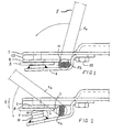
- Fig. 1 is a vertical sectional view of a knife holder mounted on a knife disc in a disc mower and in resting position,
- Fig. 2 a vertical sectional view of the knife disc shown in Fig. 1 in stressed position, and
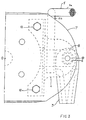
- Fig. 3 the knife disc seen from above.
-
- In Figs 1 and 2 a knife holder is shown in resting position and in stressed position, respectively, the knife holder being positioned on a
knife disc 7 for a disc mower, in which ashaft 2, which is in parallel with a rotational axis O for the disc, is fastened at one end of aleaf spring 4 of S-shape, the other end being fastened to theknife disc 7 by anut 12. Theshaft 2 is provided with ahead 6 and acircular recess 11, in which aknife 3 with ahole 10 is pivotally mounted. Thehead 6 of the shaft is embedded in a hole 9 in astop plate 8, which through a counter-sink-block 13 is fastened to thedisc 7. Thestop plate 8 is designed such that anedge 14 facing the rotational axis of theknife disc 7 extends over the knife edge when it is in its dismantling position (Fig. 3). - When exchanging knives a
suitable tool 5 is introduced under the bend of theleaf spring 4. Thistool 5 is preferably, on ahandle 5a perpendicular thereto, provided with a head 5b with an oblong cross-section, the width of which exceeds and the height of which is smaller than the distance between theleaf spring 4 and the countersink-block 13. When thetool 5 is turned under use of a suitable power, theleaf spring 4 will be stressed and a force directed away from the rotational axis O will influence the head 5b of the tool to make it skid towards theshaft 2. Theedge 14 of thestop plate 8 will, however, make the outwards movement of thetool 5 stop and a further turning of thetool 5 will move theshaft 2 away from thestop plate 8. When the distance between thehead 6 of the shaft and the countersinking 9 is bigger than the width of the knife, the knife may be dismantled easily and unhindered without the tool abutting the edge of the knife and a new knife may, if desired, be mounted. - Fig. 3 shows the knife holder, seen from above. The
leaf spring 4 is fastened to theknife disc 7 by twonuts 12 to ensure, among others, that the leaf spring is not displaced relative to the knife disc during operation.
Claims (8)
- A knife holder (1) for a disc mower, said knife holder comprising a shaft (2) for the mounting of a knife (3), said shaft being retained or tightened by a resilient means (4) against a base, the shaft being sufficiently movable away from the base to make an exchange of knife possible by stressing of the resilient means with a tool (5), said knife (3) being removable from the shaft (2) only in a position in which it is turned away from its operating position, characterized in that the knife holder is provided with a stop (14) preventing the tool (5) under the influence of the resilient means (4) from substantially skidding and being pressed towards the edge of the knife.
- A knife holder according to claim 1, characterized in that the resilient means comprises a carrier member (4) extending along the base (7), the shaft (2) thus extending from the carrier member (4) to the base (7).
- A knife holder according to claim 2, characterized in being adapted to accommodate the tool (5) between the base (7) and the carrier member (4).
- A knife holder according to claims 1-3, characterized in that the stop is constituted by an edge (14).
- A knife holder according to claims 1-4, characterized in that the base comprises a rotatable knife disc (7) and a stop plate (8) provided thereon, said stop plate being designed such that the head of the shaft may be accommodated in a hole (9) therein.
- A knife holder according to claim 5, characterized in that an edge (14) of the stop plate (8) constitutes the stop for the tool.
- A knife holder according to any of the preceding claims, characterized in that the tool (5) for influencing the resilient means (4) is designed in such a way that the highest tension which may be established by the resilient means is less than or equal to the yield point.
- A knife holder according to any of the preceding claims, characterized in that the resilient means (4) is a leaf spring which at one end is fastened to the shaft (2) and at the other end to the base (7), preferably the rotatable knife disc.
Applications Claiming Priority (3)
| Application Number | Priority Date | Filing Date | Title |
|---|---|---|---|
| DK612/96 | 1996-05-29 | ||
| DK61296 | 1996-05-29 | ||
| DK199600612A DK174349B1 (en) | 1996-05-29 | 1996-05-29 | Knife holder for a mower |
Publications (2)
| Publication Number | Publication Date |
|---|---|
| EP0809929A1 EP0809929A1 (en) | 1997-12-03 |
| EP0809929B1 true EP0809929B1 (en) | 2002-03-13 |
Family
ID=8095552
Family Applications (1)
| Application Number | Title | Priority Date | Filing Date |
|---|---|---|---|
| EP97610019A Expired - Lifetime EP0809929B1 (en) | 1996-05-29 | 1997-05-28 | A knife holder for a mower |
Country Status (3)
| Country | Link |
|---|---|
| EP (1) | EP0809929B1 (en) |
| DE (1) | DE69710944T2 (en) |
| DK (1) | DK174349B1 (en) |
Cited By (1)
| Publication number | Priority date | Publication date | Assignee | Title |
|---|---|---|---|---|
| US12550818B2 (en) | 2021-10-15 | 2026-02-17 | Techtronic Cordless Gp | Mower |
Families Citing this family (8)
| Publication number | Priority date | Publication date | Assignee | Title |
|---|---|---|---|---|
| DE19856746A1 (en) | 1998-12-09 | 2000-07-13 | Claas Saulgau Gmbh | Quick knife changing device for mowers |
| DE10018391A1 (en) * | 2000-04-13 | 2001-10-25 | Krone Bernard Maschf Gmbh | mower |
| FR2905050B1 (en) * | 2006-08-24 | 2008-10-03 | Kuhn Sa Sa | DEVICE FOR RAPID AND SECURE FIXING OF A MOWING MACHINE KNIFE, CUTTING ROTOR AND MOWING MACHINE WITH SUCH A FIXING DEVICE |
| DE102010054071A1 (en) * | 2010-06-11 | 2011-12-15 | Eberhard Christ | Device for attaching knives to a mowing or mulching machine |
| US20140126952A1 (en) * | 2012-11-02 | 2014-05-08 | Ii Jeffrey Fay | Knife nut for quick-change knives on a disc mower |
| DE102015004944B4 (en) * | 2015-04-17 | 2019-11-14 | Maschinenfabrik Bernard Krone Gmbh | Auxiliary device for changing blades on agricultural mowers |
| DE102015214051A1 (en) * | 2015-07-24 | 2017-01-26 | Deere & Company | Knife rotor for a mowing device Clamping tool and mowing device with such |
| US10820499B2 (en) | 2018-06-08 | 2020-11-03 | Cnh Industrial America Llc | Hybrid disc cutting system having a knife mount for an agricultural vehicle |
Family Cites Families (7)
| Publication number | Priority date | Publication date | Assignee | Title |
|---|---|---|---|---|
| US3662529A (en) * | 1970-10-30 | 1972-05-16 | Fahr Ag Maschf | Swinging blade arrangement for mower assembly |
| FR2138637B1 (en) * | 1971-05-26 | 1973-07-13 | Fahr Ag Maschf | |
| GB2001836B (en) * | 1977-07-13 | 1982-03-24 | Kidd A | Agricultural mower and a cutting blade therefor |
| DE3202926A1 (en) * | 1982-01-29 | 1983-08-11 | Claas Saulgau GmbH, 7968 Saulgau | ROTARY MOWER |
| DE3447154C2 (en) * | 1984-12-22 | 1998-02-19 | Stihl Maschf Andreas | Anti-rotation device for a rotatably mounted tool, in particular a cutting tool of a brush cutter |
| NL8602608A (en) * | 1986-10-17 | 1988-05-16 | Zweegers & Zonen P J | Mower for grass lawns - has elliptical cutter plate with blade mounted on pivot axis |
| ATE183612T1 (en) * | 1994-12-21 | 1999-09-15 | Kverneland Geldrop B V | ROTARY MOWER AND BLADE CHANGE TOOL |
-
1996
- 1996-05-29 DK DK199600612A patent/DK174349B1/en not_active IP Right Cessation
-
1997
- 1997-05-28 DE DE69710944T patent/DE69710944T2/en not_active Expired - Fee Related
- 1997-05-28 EP EP97610019A patent/EP0809929B1/en not_active Expired - Lifetime
Cited By (1)
| Publication number | Priority date | Publication date | Assignee | Title |
|---|---|---|---|---|
| US12550818B2 (en) | 2021-10-15 | 2026-02-17 | Techtronic Cordless Gp | Mower |
Also Published As
| Publication number | Publication date |
|---|---|
| DE69710944T2 (en) | 2002-10-31 |
| DE69710944D1 (en) | 2002-04-18 |
| DK174349B1 (en) | 2002-12-23 |
| EP0809929A1 (en) | 1997-12-03 |
| DK61296A (en) | 1997-11-30 |
Similar Documents
| Publication | Publication Date | Title |
|---|---|---|
| EP0779116B1 (en) | A quick clamping device for at least one tool of a machine tool | |
| US6959530B2 (en) | Pivotal knife mounting arrangement | |
| JP3657613B2 (en) | Milling tool for drilling | |
| EP0809929B1 (en) | A knife holder for a mower | |
| US4525990A (en) | Device for mowing crop | |
| US7743478B2 (en) | Method for changing knives in a mower | |
| CN100548593C (en) | Kitchen slicer | |
| US5511407A (en) | Upper tool for press brake | |
| US20170020067A1 (en) | Quick attach rotary mower blade system | |
| US4879936A (en) | Circular saw blade having removable teeth | |
| US5996655A (en) | Pivoting knife clamp | |
| US5678294A (en) | Procedure for replacing the knives of a disc chipper | |
| CA2054692A1 (en) | Grinding apparatus | |
| US20050193706A1 (en) | Mowing device, a knife adapter for such a mowing device and a retainer for such a mowing device | |
| GB2337224A (en) | Die cutting apparatus | |
| US5409172A (en) | System for removing a knife insert from the knife holder of a grinder | |
| US4947721A (en) | Circular saw blade having removable teeth | |
| JP3462817B2 (en) | Jig for sharpening sword | |
| US5175985A (en) | Toolholder for use in a rotary crop-cutting machine | |
| US6092573A (en) | Plane head for a planing machine | |
| EP1588599A1 (en) | A mowing device, a knife adapter for such a mowing device and a retainer for such a mowing device | |
| US5148589A (en) | Sickle section blade replacement tool | |
| EP1082889B1 (en) | A system for the rapid coupling of blades for rotary harrows | |
| US5947173A (en) | Cutting apparatus for wood or the like | |
| CN1068821C (en) | Hand-held power planer |
Legal Events
| Date | Code | Title | Description |
|---|---|---|---|
| PUAI | Public reference made under article 153(3) epc to a published international application that has entered the european phase |
Free format text: ORIGINAL CODE: 0009012 |
|
| AK | Designated contracting states |
Kind code of ref document: A1 Designated state(s): DE FI FR GB NL |
|
| 17P | Request for examination filed |
Effective date: 19980518 |
|
| AKX | Designation fees paid |
Free format text: DE FI FR GB NL |
|
| RBV | Designated contracting states (corrected) |
Designated state(s): DE FI FR GB NL |
|
| 17Q | First examination report despatched |
Effective date: 20000516 |
|
| GRAG | Despatch of communication of intention to grant |
Free format text: ORIGINAL CODE: EPIDOS AGRA |
|
| GRAG | Despatch of communication of intention to grant |
Free format text: ORIGINAL CODE: EPIDOS AGRA |
|
| GRAH | Despatch of communication of intention to grant a patent |
Free format text: ORIGINAL CODE: EPIDOS IGRA |
|
| GRAH | Despatch of communication of intention to grant a patent |
Free format text: ORIGINAL CODE: EPIDOS IGRA |
|
| REG | Reference to a national code |
Ref country code: GB Ref legal event code: IF02 |
|
| GRAA | (expected) grant |
Free format text: ORIGINAL CODE: 0009210 |
|
| AK | Designated contracting states |
Kind code of ref document: B1 Designated state(s): DE FI FR GB NL |
|
| PG25 | Lapsed in a contracting state [announced via postgrant information from national office to epo] |
Ref country code: NL Free format text: LAPSE BECAUSE OF FAILURE TO SUBMIT A TRANSLATION OF THE DESCRIPTION OR TO PAY THE FEE WITHIN THE PRESCRIBED TIME-LIMIT Effective date: 20020313 |
|
| REF | Corresponds to: |
Ref document number: 69710944 Country of ref document: DE Date of ref document: 20020418 |
|
| NLV1 | Nl: lapsed or annulled due to failure to fulfill the requirements of art. 29p and 29m of the patents act | ||
| ET | Fr: translation filed | ||
| PLBE | No opposition filed within time limit |
Free format text: ORIGINAL CODE: 0009261 |
|
| STAA | Information on the status of an ep patent application or granted ep patent |
Free format text: STATUS: NO OPPOSITION FILED WITHIN TIME LIMIT |
|
| 26N | No opposition filed |
Effective date: 20021216 |
|
| PGFP | Annual fee paid to national office [announced via postgrant information from national office to epo] |
Ref country code: GB Payment date: 20050516 Year of fee payment: 9 |
|
| PGFP | Annual fee paid to national office [announced via postgrant information from national office to epo] |
Ref country code: DE Payment date: 20050519 Year of fee payment: 9 |
|
| PGFP | Annual fee paid to national office [announced via postgrant information from national office to epo] |
Ref country code: FI Payment date: 20050520 Year of fee payment: 9 |
|
| PGFP | Annual fee paid to national office [announced via postgrant information from national office to epo] |
Ref country code: FR Payment date: 20050523 Year of fee payment: 9 |
|
| PG25 | Lapsed in a contracting state [announced via postgrant information from national office to epo] |
Ref country code: GB Free format text: LAPSE BECAUSE OF NON-PAYMENT OF DUE FEES Effective date: 20060528 Ref country code: FI Free format text: LAPSE BECAUSE OF NON-PAYMENT OF DUE FEES Effective date: 20060528 |
|
| PG25 | Lapsed in a contracting state [announced via postgrant information from national office to epo] |
Ref country code: DE Free format text: LAPSE BECAUSE OF NON-PAYMENT OF DUE FEES Effective date: 20061201 |
|
| GBPC | Gb: european patent ceased through non-payment of renewal fee |
Effective date: 20060528 |
|
| REG | Reference to a national code |
Ref country code: FR Ref legal event code: ST Effective date: 20070131 |
|
| PG25 | Lapsed in a contracting state [announced via postgrant information from national office to epo] |
Ref country code: FR Free format text: LAPSE BECAUSE OF NON-PAYMENT OF DUE FEES Effective date: 20060531 |