EP0809464B1 - System for examining heart tissue - Google Patents
System for examining heart tissue Download PDFInfo
- Publication number
- EP0809464B1 EP0809464B1 EP96906520A EP96906520A EP0809464B1 EP 0809464 B1 EP0809464 B1 EP 0809464B1 EP 96906520 A EP96906520 A EP 96906520A EP 96906520 A EP96906520 A EP 96906520A EP 0809464 B1 EP0809464 B1 EP 0809464B1
- Authority
- EP
- European Patent Office
- Prior art keywords
- pacing
- electrode
- template
- sample
- electrogram
- Prior art date
- Legal status (The legal status is an assumption and is not a legal conclusion. Google has not performed a legal analysis and makes no representation as to the accuracy of the status listed.)
- Expired - Lifetime
Links
Images


Classifications
-
- A—HUMAN NECESSITIES
- A61—MEDICAL OR VETERINARY SCIENCE; HYGIENE
- A61B—DIAGNOSIS; SURGERY; IDENTIFICATION
- A61B5/00—Measuring for diagnostic purposes; Identification of persons
- A61B5/68—Arrangements of detecting, measuring or recording means, e.g. sensors, in relation to patient
- A61B5/6846—Arrangements of detecting, measuring or recording means, e.g. sensors, in relation to patient specially adapted to be brought in contact with an internal body part, i.e. invasive
- A61B5/6847—Arrangements of detecting, measuring or recording means, e.g. sensors, in relation to patient specially adapted to be brought in contact with an internal body part, i.e. invasive mounted on an invasive device
- A61B5/6852—Catheters
- A61B5/6855—Catheters with a distal curved tip
-
- A—HUMAN NECESSITIES
- A61—MEDICAL OR VETERINARY SCIENCE; HYGIENE
- A61B—DIAGNOSIS; SURGERY; IDENTIFICATION
- A61B5/00—Measuring for diagnostic purposes; Identification of persons
- A61B5/24—Detecting, measuring or recording bioelectric or biomagnetic signals of the body or parts thereof
- A61B5/25—Bioelectric electrodes therefor
- A61B5/279—Bioelectric electrodes therefor specially adapted for particular uses
- A61B5/28—Bioelectric electrodes therefor specially adapted for particular uses for electrocardiography [ECG]
- A61B5/283—Invasive
- A61B5/287—Holders for multiple electrodes, e.g. electrode catheters for electrophysiological study [EPS]
-
- A—HUMAN NECESSITIES
- A61—MEDICAL OR VETERINARY SCIENCE; HYGIENE
- A61B—DIAGNOSIS; SURGERY; IDENTIFICATION
- A61B5/00—Measuring for diagnostic purposes; Identification of persons
- A61B5/68—Arrangements of detecting, measuring or recording means, e.g. sensors, in relation to patient
- A61B5/6846—Arrangements of detecting, measuring or recording means, e.g. sensors, in relation to patient specially adapted to be brought in contact with an internal body part, i.e. invasive
- A61B5/6847—Arrangements of detecting, measuring or recording means, e.g. sensors, in relation to patient specially adapted to be brought in contact with an internal body part, i.e. invasive mounted on an invasive device
- A61B5/6852—Catheters
- A61B5/6858—Catheters with a distal basket, e.g. expandable basket
-
- A—HUMAN NECESSITIES
- A61—MEDICAL OR VETERINARY SCIENCE; HYGIENE
- A61N—ELECTROTHERAPY; MAGNETOTHERAPY; RADIATION THERAPY; ULTRASOUND THERAPY
- A61N1/00—Electrotherapy; Circuits therefor
- A61N1/02—Details
- A61N1/04—Electrodes
- A61N1/05—Electrodes for implantation or insertion into the body, e.g. heart electrode
- A61N1/056—Transvascular endocardial electrode systems
-
- A—HUMAN NECESSITIES
- A61—MEDICAL OR VETERINARY SCIENCE; HYGIENE
- A61B—DIAGNOSIS; SURGERY; IDENTIFICATION
- A61B18/00—Surgical instruments, devices or methods for transferring non-mechanical forms of energy to or from the body
- A61B18/04—Surgical instruments, devices or methods for transferring non-mechanical forms of energy to or from the body by heating
- A61B18/12—Surgical instruments, devices or methods for transferring non-mechanical forms of energy to or from the body by heating by passing a current through the tissue to be heated, e.g. high-frequency current
- A61B18/14—Probes or electrodes therefor
- A61B18/1492—Probes or electrodes therefor having a flexible, catheter-like structure, e.g. for heart ablation
-
- A—HUMAN NECESSITIES
- A61—MEDICAL OR VETERINARY SCIENCE; HYGIENE
- A61B—DIAGNOSIS; SURGERY; IDENTIFICATION
- A61B90/00—Instruments, implements or accessories specially adapted for surgery or diagnosis and not covered by any of the groups A61B1/00 - A61B50/00, e.g. for luxation treatment or for protecting wound edges
- A61B90/06—Measuring instruments not otherwise provided for
- A61B2090/064—Measuring instruments not otherwise provided for for measuring force, pressure or mechanical tension
- A61B2090/065—Measuring instruments not otherwise provided for for measuring force, pressure or mechanical tension for measuring contact or contact pressure
-
- A—HUMAN NECESSITIES
- A61—MEDICAL OR VETERINARY SCIENCE; HYGIENE
- A61B—DIAGNOSIS; SURGERY; IDENTIFICATION
- A61B2562/00—Details of sensors; Constructional details of sensor housings or probes; Accessories for sensors
- A61B2562/04—Arrangements of multiple sensors of the same type
- A61B2562/043—Arrangements of multiple sensors of the same type in a linear array
Definitions
- the invention relates to a system for examining heart tissue according to the precharacterizing part of claim 1.
- SA node sinoatrial node
- the impulse causes adjacent myocardial tissue cells in the atria to depolarize, which in turn causes adjacent myocardial tissue cells to depolarize.
- the depolarization propagates across the atria, causing the atria to contract and empty blood from the atria into the ventricles.
- the impulse is next delivered via the atrioventricular node (or "AV node") and the bundle of HIS (or "HIS bundle”) to myocardial tissue cells of the ventricles. The depolarization of these cells propagates across the ventricles, causing the ventricles to contract.
- This conduction system results in the described, organized sequence of myocardial contraction leading to a normal heartbeat.
- anatomical obstacles in the atria or ventricles can disrupt the normal propagation of electrical impulses. These anatomical obstacles (called “conduction blocks”) can cause the electrical impulse to degenerate into several circular wavelets that circulate about the obstacles. These wavelets, called “reentry circuits,” disrupt the normal activation of the atria or ventricles.
- conduction blocks can cause the electrical impulse to degenerate into several circular wavelets that circulate about the obstacles. These wavelets, called “reentry circuits,” disrupt the normal activation of the atria or ventricles.
- localized regions of ischemic myocardial tissue may propagate depolarization events slower than normal myocardial tissue.
- the ischemic region also called a “slow conduction zone,” creates errant, circular propagation patterns, called “circus motion.”
- the circus motion also disrupts the normal depolarization patterns, thereby disrupting the normal contraction of heart tissue.
- arrhythmias The aberrant conductive pathways create abnormal, irregular, and sometimes life-threatening heart rhythms, called arrhythmias.
- An arrhythmia can take place in the atria, for example, as in atrial tachycardia (AT) or atrial flutter (AF).
- AT atrial tachycardia
- AF atrial flutter
- the arrhythmia can also take place in the ventricle, for example, as in ventricular tachycardia (VT).
- AT atrial tachycardia
- AF atrial flutter
- VT ventricular tachycardia
- the location of the sources of the aberrant pathways (call foci) be located. Once located, the tissue in the foci can be destroyed, or ablated, by heat, chemicals, or other means. Ablation can remove the aberrant conductive pathway, restoring normal myocardial contraction.
- mapping identify regions in the heart tissue, called foci, which can be ablated to treat the arrhythmia.
- One form of conventional cardiac tissue mapping techniques uses multiple electrodes positioned in contact with epicardial heart tissue to obtain multiple electrograms.
- the physician stimulates myocardial tissue by introducing pacing signals and visually observes the morphologies of the electrograms recorded during pacing, which this Specification will refer to as "paced electrograms.”
- the physician visually compares the patterns of paced electrograms to those previously recorded during an arrhythmia episode to locate tissue regions appropriate for ablation.
- These conventional mapping techniques require invasive open heart surgical techniques to position the electrodes on the epicardial surface of the heart.
- pace mapping Another form of conventional cardiac tissue mapping technique, called pace mapping, uses a roving electrode in a heart chamber for pacing the heart at various endocardial locations.
- the physician In searching for the VT foci, the physician must visually compare all paced electrocardiograms (recorded by twelve lead body surface electrocardiograms (ECG's)) to those previously recorded during an induced VT.
- ECG's lead body surface electrocardiograms
- the physician must constantly relocate the roving electrode to a new location to systematically map the endocardium.
- artifacts caused by the pacing signals can distort the electrocardiograms.
- the pacing artifacts can mask the beginning of the Q-wave in the electrocardiogram.
- the morphology of the pacing artifact visually differs from the morphology of the electrocardiogram.
- a trained physician is therefore able to visually differentiate between a pacing artifact and the electrocardiogram morphology. This is not always the case in endocardial or epicardial mapping, in which there can be a very close similarity between the morphology of the pacing artifact and the bipolar electrogram morphology.
- the pacing artifact and electrogram complex are separated in time, and therefore can be distinguished from one another by a trained physician.
- the presence of the pacing artifact can sometimes mask the entire bipolar electrogram.
- its likeness to the bipolar electrogram often makes it difficult or impossible for even a trained physician to detect the beginning of depolarization with accuracy.
- US-A-5 324 284 discloses a catheter probe having a plurality of spaced-apart mapping electrodes on its distal extremity, and a separate steerable ablation catheter that is deployable independently of the catheter probe to ablate a site identified by the mapping electrodes.
- a principal objective of the invention is to provide improved systems and methods to examine heart tissue morphology quickly and accurately.
- the invention provides systems using an array of multiple electrodes supported for operative association with a region of heart tissue, in tandem with a roving second electrode supported for movement relative to the multiple electrodes for operative association with selected, different regions of endocardial tissue within the heart.
- An analog or digital processing element is coupled to the multiple electrodes and the roving electrode for conditioning one of the multiple electrodes and the roving electrode to emit a pacing signal, while the other one of the multiple electrodes and the roving electrode records paced electrograms occurring as a result of the pacing signal.
- Another embodiment of the invention provides a processing element that inputs a template of a cardiac event of known diagnosis sensed using an array of multiple electrodes supported for operative contact with a region of heart tissue.
- the processing element inputs a sample of a cardiac event acquired by pacing from the roving electrode in operative association with a region of endocardial tissue and sensed with the array of multiple electrodes.
- the processing element electronically compares the input sample to the input template and generate an output based upon the comparison.
- the output is a matching factor that aids the physician in locating potentially appropriate sites for ablation.
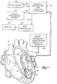
- Fig. 1A shows the components of a system 10 for analyzing body tissue biopotential morphologies for diagnostic or therapeutic purposes.
- the illustrated embodiment shows the system 10 being used to examine the depolarization of heart tissue that is subject to an arrhythmia.
- the system 10 serves to locate an arrhythmogenic focus for removal by ablation.
- the invention is well suited for use in conducting electrical therapy of the heart.
- the invention is applicable for use in other regions of the body where tissue biopotential morphologies can be ascertained by analyzing electrical events in the tissue.
- the various embodiments of the invention have application in procedures for analyzing brain or neurologic tissue.
- Fig. 1A shows the system 10 analyzing endocardial electrical events, using catheter-based, vascular access techniques. Still, many aspects of the invention can be used in association with techniques that do not require any intrusion into the body, like surface electrocardiograms or electroencephalograms. Many of the aspects of the invention also can be used with invasive surgical techniques, like in open chest or open heart surgery, or during brain surgery.
- FIG. 1A shows the system 10 analyzing electrical events within a selected region 12 inside a human heart.
- Figs. 1A and 1B generally show the system 10 deployed in the left ventricle of the heart. Of course, the system 10 can be deployed in other regions of the heart, too. It should also be noted that the heart shown in the Fig. 1 is not anatomically accurate.
- Figs. 1A and 1B show the heart in diagrammatic form to demonstrate the features of the invention.
- the system 10 includes a mapping probe 14 and an ablation probe 16.
- a mapping probe 14 and an ablation probe 16 are separately introduced into the selected heart region 12 through a vein or artery (typically the femoral vein or artery) through suitable percutaneous access.
- the mapping probe 14 and ablation probe 16 can be assembled in an integrated structure for simultaneous introduction and deployment in the heart region 12.
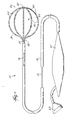
- the mapping probe 14 has a flexible catheter body 18.
- the distal end of the catheter body 18 carries a three dimensional multiple-electrode structure 20.
- the structure 20 takes the form of a basket defining an open interior space 22 (see Fig. 2). It should be appreciated that other three dimensional structures could be used.
- the illustrated basket structure 20 comprises a base member 26 and an end cap 28.
- Generally flexible splines 30 extend in a circumferentially spaced relationship between the base member 26 and the end cap 28.
- the splines 30 are preferably made of a resilient, biologically inert material, like Nitinol metal or silicone rubber.
- the splines 30 are connected between-the base member 26 and the end cap 28 in a resilient, pretensed, radially expanded condition, to bend and conform to the endocardial tissue surface they contact.
- eight splines 30 form the basket structure 20. Additional or fewer splines 30 could be used.
- the splines 30 carry an array of electrodes 24.
- each spline 30 carries eight electrodes 24.
- additional or fewer electrodes 24 can be used.
- a slidable sheath 19 is movable along the axis of the catheter body 18 (shown by arrows in Fig. 2). Moving the sheath 19 forward causes it to move over the basket structure 20, collapsing it into a compact, low profile condition for introducing into the heart region 12. Moving the sheath 19 rearward frees the basket structure 20, allowing it to spring open and assume the pretensed, radially expanded position shown in Fig. 2. The electrodes are urged into contact against the surrounding heart tissue.
- the electrodes 24 sense electrical events in myocardial tissue for the creation of electrograms.
- the electrodes 24 are electrically coupled to a process controller 32 (see Fig. 1A).
- a signal wire (not shown) is electrically coupled to each electrode 24.
- the wires extend through the body 18 of the probe 14 into a handle 21, in which they are coupled to an external multiple pin connector 23.
- the connector 23 electrically couples the electrodes to the process controller 32.
- multiple electrode structures can be located epicardially using a set of catheters individually introduced through the coronary vasculature (e.g., retrograde through the aorta or coronary sinus), as disclosed in PCT/US94/01055 entitled “Multiple Intravascular Sensing Devices for Electrical Activity.”
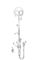
- the ablation probe 16 (see Fig. 3) includes a flexible catheter body 34 that carries one or more ablation electrodes 36.
- Fig. 3 shows a single ablation electrode 36 carried at the distal tip of the catheter body 34.
- other configurations employing multiple ablation electrodes are possible, as described in pending U.S. Patent No. 5,582,609, filed August 8, 1994, entitled “Systems and Methods for Ablating Heart Tissue Using Multiple Electrode Elements.”
- a handle 38 is attached to the proximal end of the catheter body 34.
- the handle 38 and catheter body 34 carry a steering mechanism 40 for selectively bending or flexing the catheter body 34 along its length, as the arrows in Fig. 3 show.
- the steering mechanism 40 can vary.
- the steering mechanism can be as shown in U.S. Patent 5,254,088.
- a wire (not shown) electrically connected to the ablation electrode 36 extends through the catheter body 34 into the handle 38, where it is electrically coupled to an external connector 45.
- the connector 45 connects the electrode 36 to a generator 46 of ablation energy.
- the type of energy used for ablation can vary.
- the generator 46 supplies electromagnetic radio frequency energy, which the electrode 36 emits into tissue.
- a radio frequency generator Model EPT-1000, available from EP Technologies, Inc., Sunnyvale, California, can be used for this purpose.
- the physician places the ablation electrode 36 in contact with heart tissue at the site identified for ablation.
- the ablation electrode emits ablating energy to heat and thermally destroy the contacted tissue.
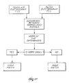
- the process controller 32 employs -electrogram matching to automatically locate for the physician the site or sites potentially appropriate for ablation.
- the process controller 32 is operable to sense electrical events in heart tissue and to process and analyze these events to achieve the objectives of the invention.
- the process controller 32 is also selectively operable to induce electrical events by transmitting pacing signals into heart tissue.
- the process controller 32 is electrically coupled by a bus 47 to a pacing module 48, which paces the heart sequentially through individual or pairs of electrodes to induce depolarization. Details of the process controller 32 and pacing module 48 are described in copending U.S. Patent No. 5,494,042, filed January 28, 1994, and entitled "Systems and Methods for Deriving Electrical Characteristics of Cardiac Tissue for Output in Iso-Characteristic Displays.”
- the process controller 32 is also electrically coupled by a bus 49 to a signal processing module 50.
- the processing module 50 processes cardiac signals into electrograms.
- a Model TMS 320C31 processor available from Spectrum Signal Processing, Inc. can be used for this purpose.
- the process controller 32 is further electrically coupled by a bus 51 to a host processor 52, which processes the input from the electrogram processing module 50 in accordance with the invention to locate arrhythmogenic foci.
- the host processor 32 can comprise a 486-type microprocessor.
- the process controller 32 operates in two functional modes, called the sampling mode and the matching mode.
- the physician deploys the basket structure 20 in the desired heart region 12.
- the physician may have to collapse the basket structure 20, rotate it, and then free the basket structure 20.
- the degree of contact can be sensed by the process controller 32 in various ways.
- the process controller 32 can condition the pacing module 48 to emit pacing signals through a selected electrode 24 or pair of electrodes 24.
- the process controller 32 conditions the electrodes 24 and processing module 50 to detect electrograms sensed by a desired number of the electrodes 24.
- the processing module can also ascertain the desired degree of contact by measuring tissue impedance, as described in copending patent No. 5,598,848, filed March 31, 1994, and entitled "Systems and Methods for Positioning Multiple Electrode Structures in Electrical Contact with the Myocardium.”
- the process controller 32 conditions the electrodes 24 and signal processing module 50 to record electrograms during a selected cardiac event having a known diagnosis. In the sampling mode, the process controller 32 typically must condition the pacing module 48 to pace the heart until the desired cardiac event is induced. Of course, if the patient spontaneously experiences the cardiac event while the structure 20 is positioned, then paced-induction is not required.
- the processor controller 32 saves these electrograms in the host processor 52.
- the process controller 32 creates templates of selected electrogram morphologies by any conventional method, e.g., by having the physician manually select representative electrogram morphologies.
- the process controller 32 typically must condition the pacing module 48 to pace terminate the cardiac event, or the physician may apply a shock to restore normal sinus rhythm.
- the matching mode is conducted without altering the position of the multiple electrode structure 20 in the heart region 12, so that the electrodes 24 occupy the same position during the matching mode as they did during the sampling mode.
- the process controller 32 conditions the pacing module 48 to pace the heart in a prescribed manner without inducing the cardiac event of interest, while conditioning the signal processing module 50 to record the resulting electrograms.
- the process controller 32 operates the host processor 52 to compare the resulting paced electrogram morphologies to the electrogram morphology templates collected during the sampling mode. Based upon this comparison, the host processor 52 generates an output that identifies the location of the electrode or electrodes 24 on the structure 20 that are close to a potential ablation site.
- the process controller 32 operates in the sampling mode while the heart is experiencing a selected cardiac event of known diagnosis and the basket structure 20 is retained in a fixed location in the region 12.
- the selected event comprises an arrhythmia that the physician seeks to treat, for example, ventricular tachycardia (VT), or atrial tachycardia (AT), or atrial fibrillation (AF).
- VT ventricular tachycardia
- AT atrial tachycardia
- AF atrial fibrillation
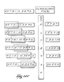
- the signal processing module 50 processes the electrogram morphologies obtained from each electrode during the known cardiac event (designated for the purpose of illustration as E1 to E3 in Fig. 4A).
- the electrograms may be recorded unipolar (between an electrode 24 and a reference electrode, not shown) or bipolar (between electrodes 24 on the structure 20).
- the host processor 52 creates a digital, event-specific template for the morphology sensed at each electrode (designated for the purpose of illustration as T1 to T3 in Fig. 4A).
- the event-specific templates T1 to T3 for each electrode E1 to E3 can be based upon electrogram morphology from one heart beat or a specified number of heart beats.
- the event-specific template T1 to T3 for each electrode E1 to E3 can be created by, for example, having the physician manually select representative electrogram morphologies.
- the template preferably comprises one heart beat and is updated beat by beat. Also preferably, though not essential, the starting point of the template should coincide with the beginning of the depolarization and extend one beat from that point. However, if the arrhythmia event under study is polymorphic, it may be necessary to extend the template over several beats. For example, in bigeminy cases, the template should preferably extend over two beats.
- the host processor 52 retains the set of event-specific templates T1 to T3 in memory.
- the processor 52 can, for an individual patient, retain sets of event-specific templates for different cardiac events. For example, a patient may undergo different VT episodes, each with a different morphology.
- the processor 52 can store templates for each VT episode for analysis according to the invention.
- the templates can be downloaded to external disk memory for off-line matching at a subsequent time, as will be described later. Templates can also be generated based upon mathematical modeling or empirical data and stored for later matching for diagnostic purposes.
- the process controller 32 operates the pacing module 48 to apply pacing signals sequentially to each of the individual electrodes.
- the pacing electrode is designated Ep in Fig. 4A.
- the pacing signal induces depolarization, emanating at the location of the pacing electrode Ep.
- the process controller 32 operates the signal processing module 50 to process the resulting paced electrogram morphologies sensed at each electrode (again designated E1 to E3 for the purpose of illustration in Fig. 4A) during pacing by the selected individual electrode Ep.
- the processed paced electrograms are designated P1 to P3 in Fig. 4A.
- the paced morphology P1 to P3 at each electrode can be from one heart beat or a specified number of heart beats, provided that the length of the morphologies P1 to P3 is not shorter than the length of the event-specific templates T1 to T3 for the same electrodes E1 to E3 obtained during the sampling mode.
- Different conventional pacing techniques can be used to obtain the paced morphologies P1 to P3.
- conventional pace mapping can be used, during which the pace rate is near the arrhythmia rate, but arrhythmia is not induced.
- entrainment or reset pacing is the preferred technique.
- the pacing rate is slightly higher than and the period slightly lower than that observed during the arrhythmia event, thereby increasing the rate of the induced arrhythmia event. Further details of entrainment pacing are found in Almendral et al., "Entrainment of Ventricular Tachycardia: Explanation for Surface Electrocardiographic Phenomena by Analysis of Electrograms Recorded Within the Tachycardia Circuit," Circulation, vol. 77, No. 3, March 1988, pages 569 to 580.
- the pacing stimulus may be monophasic, biphasic, or triphasic.
- the host processor 52 compares the paced morphology P1 to P3 obtained at each electrode E1 to E3 to the stored event-specific template T1 to T3 for the same electrode E1 to E3.
- the comparisons (which are designated C1 to C3 in Fig. 4A) can be performed by using matched filtering or correlation functions, as will be described later.
- the paced morphologies P1 to P3 can be retained in memory or downloaded to external disk memory for matching at a later time.
- the host processor 52 preferably includes an input module 72 for uploading pregenerated templates and/or paced morphologies recorded at an earlier time.
- the input module 72 allows templates and paced morphologies to be matched off-line by the host processor 52, without requiring the real time presence of the patient.
- recorded paced morphologies can be matched in real time using templates generated earlier.
- the pregenerated templates can represent "typical" biopotential events based upon either real, empirical data, or mathematical models for diagnostic purposes, or reflect earlier biopotential events recorded for the same patient or for a patient having the same or similar prognosis.
- the host processor 52 For each pacing electrode Ep(j), the host processor 52 generates a matching coefficient M COEF(i) for each electrode E(i) from the comparison C(i) of the pacing morphology P(i) to the template morphology T(i) for the same electrode E(i).
- both j and i 1 to n, where n is the total number of electrodes on the three dimensional structure (which, for the purpose of illustration in Fig. 4A, is 3).
- the value of the matching coefficient M COEF(i) is indicative for that electrode E(i) how alike the pacing morphology P(i) is to the event-specific template T(i) for that electrode E(i).
- the value of M COEF(i) for each electrode E(i) varies as the location of the pacing electrode Ep(j) changes.
- the value of the matching coefficient M COEF(i) for a given electrode E(i) increases in relation to the closeness of the pacing electrode Ep(j) to the arrhythmogenic foci.
- the host processor 52 while pacing at an individual one of the electrodes Ep(j), the host processor 52 generates from the matching coefficients M COEF(i) for each electrode E(i) an overall matching factor M PACE(j) for the pacing electrode Ep(j).
- the value of the overall matching factor M PACE(j) for the pacing electrode Ep(j) is indicative of how alike the overall propagation pattern observed during pacing at the electrode Ep(j) is to the overall propagation pattern recorded on the associated event-specific templates.
- the process controller 32 operates the pacing module 48 to apply a pacing signal sequentially to each electrode Ep(j) and processes and compares the resulting electrogram morphologies at each electrode E(i) (including Ep(j)) to the event-specific templates, obtaining the matching coefficients M COEF(i) for each electrode E(i) and an overall matching factor M PACE(j) for the pacing electrode Ep(j), and so on, until every electrode E(i) serves as a pacing electrode Ep(j).
- M PACE(j) for each pacing electrode can be derived from associated matching coefficients M COEF(i) in various ways.
- the value of the overall matching factor M PACE(j) increases in relation to the proximity of the particular pacing electrode Ep(j) to a potential ablation site.
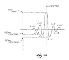
- the site appropriate for ablation typically constitutes a slow conduction zone, designated SCZ in Fig. 4B.
- Depolarization wave fronts (designated DWF in Fig. 4B) entering the slow conduction zone SCZ (at site A in Fig. 4B) break into errant, circular propagation patterns (designated B and C in Fig. 4B), called "circus motion.”
- the circus motions disrupt the normal depolarization patterns, thereby disrupting the normal contraction of heart tissue to cause the cardiac event.
- the event-specific templates T(i) record these disrupted depolarization patterns.
- the pacing signal gets caught in the same circus motion (i.e., paths B and C in Fig. 4B) that triggers the targeted cardiac event.
- a large proportion of the associated pacing morphologies P(i) at the sensing electrodes E(i) will therefore match the associated event-specific templates P(i) recorded during the targeted cardiac event. This leads to a greater number of larger matching coefficients M COEF(i) and thus to a larger overall matching factor M PACE(j) .
- Ablating tissue in or close to the slow conduction zone prevents subsequent depolarization.
- the destroyed tissue is thereby "closed” as a possible path of propagation.
- Depolarization events bypass the ablated region and no longer become caught in circus motion. In this way, ablation can restore normal heart function.
- the matching of pacing morphologies P(i) to template morphologies T(i) to create the matching coefficient M COEF(i) and the overall matching factor M PACE(i) can be accomplished in various ways.
- the host processor 52 can employ pattern matching; symmetry matching; matched filtering; cross correlation; or norm of the difference techniques. The following provides an overview of each of these techniques.
- Fig. 5 diagrammatically shows a pattern matching technique that embodies features of the invention.
- the pattern matching technique matched filters the template T(i) for each electrode E(i) using the same template flipped left to right with respect to time, Tflip(i), as coefficients of the matched filter.
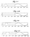
- Fig. 6B shows a representative template T(i) for a given electrode E(i).
- Fig. 6C shows Tflip(i), which is the template T(i) (shown in Fig. 6B) flipped right to left.
- Fig. 6E shows a matched filtered output MT(i), which had T(i) (Fig. 6B) as input and Tflip(i) (Fig. 6C) for the same electrode E(i) as coefficients of the matched filter.
- the matched filtered output MT(i) is, for the electrode E(i), a sequence of alternating maximums and minimums, with their values marking a first pattern employed by this technique.
- the pattern matching technique also matched filters the paced electrogram P(i) for each electrode E(i) using an identical matched filter as the one described above.
- Fig. 6A shows a representative paced electrogram P(i) for the given electrode E(i).
- Fig. 6D shows the matched filtered output MP(i), using Tflip(i) shown in Fig. 6C as the matched filtered coefficients.
- the matched filtered output MP(i) is, for each electrode E(i), a sequence of alternating maximums and minimums, which are used to construct a second pattern.
- the pattern matching technique detects the maximums and minimums for the matched filtered template outputs MT(i) and those of MP(i).
- the pattern matching technique computes the norm of the difference between the MP-pattern and the corresponding MT-pattern shifted by an amount, P, that varies from -K to K, where K L/2.
- the maximum number of comparisons for n electrodes will be n comparisons for each pacing electrode.
- the largest excursions are placed in the centers of the template and paced vectors.
- M PACE(j) ⁇ M COEF(i) n
- Fig. 7A shows a symmetry matching technique that embodies features of the invention.
- the symmetry matching technique matched filters the paced electrogram P(i) for each electrode E(i) using Tflip(i) as coefficients of the matched filter.
- Similar electrograms will create a matched filtered output having a positive largest excursion. As the degree of similarity between the two electrograms increases, the matched filtered output will become increasingly more symmetric about this positive absolute maximum.
- the scoring factors based upon SYM are converted to an overall matching factor M PACE(j) for each pacing electrode Ep(j), as previously described.
- the pacing electrode Ep(j) creating the highest overall matching factor is designated to be close to a potential ablation site.
- Fig. 6E shows the matched filtered output MT(i) of the template electrogram of Fig. 6B and its left-to-right flipped counterpart of Fig. 6C.
- the electrogram of Fig. 6B is, in effect, matched filtered against itself, and the symmetry matching technique detects this.
- Fig. 6E shows a largest excursion that is positive and an output that is perfectly symmetric about the positive absolute maximum.
- a perfect scoring factor M COEF(i) of 1.0 would be assigned.
- Fig. 6D is the matched filtered output MP(i) of the electrogram of Fig. 6A and the flipped template in Fig. 6C. These are different, yet similar electrograms.
- the symmetry matching technique detects this close similarity.
- Fig. 6D shows a positive largest excursion, and the output is relatively symmetric about this positive absolute maximum.
- a good scoring factor M COEF(i) of, for example, 0.9 would be assigned.
- Fig. 8C is the matched filtered output of the electrogram of Fig. 6A using the flipped template shown in Fig. 8B as coefficient of the matched filter. It can be seen that the electrogram shown in Fig. 8A has a morphology quite different than that shown in Fig. 6A. The symmetry matching technique detects this difference. Fig. 8C shows a negative largest excursion and an output that is not symmetric about this absolute maximum. A poor scoring factor M COEF(i) of zero would be assigned.
- Fig. 9 shows a technique matching against Dirac pulse that embodies features of the invention.
- This matching technique employs a whitening algorithm to first filter the template electrograms and the paced electrograms.
- the whitening filter transforms so-called colored noise, which can be 60-Hz (or 50-Hz) interference, or motion or muscular artifacts of the patient, to white noise.
- the technique matched filters the whitened paced electrogram for each electrode using the left-right flipped, whitened template for that electrode as coefficients of the matched filter. Ideally, exactly matched, whitened electrograms will produce an output that equals a Dirac pulse. Therefore, each filter output is compared to a Dirac pulse. An algorithm scores the similarity for each electrode.
- the pacing electrode whose whitened, matched filtered output most closely resembles a Dirac pulse is designated to be close to a potential ablation site.
- Fig. 10 shows a cross correlation technique that embodies features of the invention.
- This technique uses an appropriate algorithm to calculate for each electrode the cross correlation function between the template electrogram and the paced electrogram. For identical electrograms, the largest excursion of the cross correlation function will equal 1.0.
- M COEF(i) is equal to the largest excursion of the sequence ⁇ rxy(k) ⁇ computed for the individual electrode E(i) (i.e., the largest excursion can be either negative or positive, depending upon the degree of intercorrelation).
- the pacing electrode Ep(j) having an overall matching factor M PACE(j) closest to 1.0 is designated to be close to a potential ablation site. Additional information may be contained in the shift parameter k for each electrode.
- Fig. 11A shows the cross correlation function for the electrograms of Fig. 6A and Fig. 6B. These electrograms are quite similar, and the cross correlation technique detects this.
- the largest excursion of the cross correlation function in Fig. 11A is near 1.0 (i.e., it is 0.9694).
- Fig. 11B shows the cross correlation function for the unlike electrograms shown in Figs. 6A and 8A.
- the cross correlation technique detects this lack of similarity.
- the largest excursion in Fig. 11B is negative (i.e., it is -0.7191).
- Fig. 12 shows a norm of the difference technique that embodies features of the invention.
- This technique normalizes, for each electrode, the template electrogram with respect to the absolute value of its largest excursion from baseline. This technique also normalizes, for each electrode, the paced electrogram with respect to the largest excursion from baseline. The technique then calculates, for each electrode, the norm of the difference between the template electrogram and the paced electrogram. The norm will decrease in proportion to the similarity of the electrograms.
- Fig. 13A is the difference between the similar electrograms shown in Figs. 6A and 6B, after each was normalized with respect to its largest excursion. This technique detects the similarity with a relatively small norm of the difference (i.e., it is 0.9620).
- Fig. 13B is the difference between the dissimilar electrograms shown in Figs. 6A and 8A, after each was normalized with respect to its largest excursion. This technique detects the lack of similarity with a relatively high norm of the difference (i.e., it is 2.4972).
- the technique preferably uses a weighted averaging algorithm to average, for each pacing electrode, the norm of the differences for all recording electrodes.
- the pacing electrode having the smallest average norm of the differences is designated the appropriate place to ablate.
- the electrograms may or may not be filtered before analysis.
- a 1 to 300 Hz bandpass filter may be used for filtering. If a filter is used to reduce the noise for an electrogram that is used as a template, the same filter must also be used for the paced electrograms, since filtering may alter the electrogram morphology.
- the electrograms might need to be aligned prior to processing. Any columnar alignment technique can be used. For example, the electrograms could be aligned about the point of largest positive slope.
- an analog matched filter can be implemented with analog integrators and adders.
- optical realizations of such filters can be implemented, for example, by using optical slots to represent the template. After optical conversion, the input signal is passed through the optical slot. The average light intensity behind the optical slot plane is maximal when the shape of the optically converted input signal matches the shape of the slot.
- An optical sensor can measure the average light intensity and output a signal that represents the matched coefficient M COEF(i) .
- the host processor 52 sets a match target N Match , which numerically establishes a matching factor M PACE(j) at which a high probability exists that the pacing electrode is close to a potential ablation site.
- N MATCH 0.8.
- M PACE(j) > N MATCH the host processor 52 deems the location of the pacing electrode Ep(j) to be close to a potential site for ablation.
- the host processor 52 transmits a SITE signal to an associated output display device 54 (see Fig. 1A). Through visual prompts, the display device 54 notifies the physician of the location of the pacing electrode Ep(j) and suggests that the location as a potential ablation site.
- the host processor 52 sorts to locate the M PACE(j) having the highest value. In this instance, the host processor 52 deems the pacing electrode Ep(j) with the highest M PACE(j) to be the one having the highest likelihood for being close to a potential ablation site and transmits the SITE signal accordingly.
- the process controller 32 provides iterative pacing and matching using different pacing and matching techniques. Using different pacing-and-compare techniques allows the comparison of the location output from one technique with the location output from one or more different techniques. Using iterative pacing and matching, the process controller 32 and the host processor 52 confirm and cross-check the location output to verify its accuracy before ablation. The host processor 52 can also rely upon alternative diagnostic techniques to analyze the biopotential morphology.
- the system 10 also includes a roving pacing probe 68 usable in tandem with the basket structure 20 to generate and verify the location output.
- the process controller 32 includes a module 60 that allows the physician to select among different types of pacing techniques.
- the different pacing techniques allow the physician to conduct both global and localized site identification, with and without inducing the abnormal cardiac event.
- At least one technique is appropriate for pacing a large tissue region to identify a subregion close to a potential ablation site, without the need to induce an abnormal cardiac event.
- the process controller 32 first conditions the pacing module 48 in the mode to conduct pace mapping. Pace mapping uses all electrodes 24 on the structure 20 in sequence as the pacing electrode, and does not induce the cardiac event. Based upon pace mapping, the process controller 32 obtains a location output that points to a general subregion that is close to a potential ablation site.
- the process controller 32 conditions the pacing module 48 in the matching mode to carry out entrainment or reset pacing, using the electrodes in the general subregion as the pacing electrodes. Entrainment or reset pacing in this subregion overdrives the arrhythmia, and provides enhanced differentiation of slow conduction zones. The process controller 32 thereby obtains a location output that is more localized with respect to the potential ablation site.
- the process controller 32 also includes a module 62 that allows the physician to select more than one matching technique during iterative pacing.
- the process controller 32 may, during pace mapping or entrainment/reset pacing, compare the templates to the paced electrograms by first pattern matching, then by symmetry matching, and then by norm of the difference. In this way, the process controller 32 determines the uniformity of the location output among the different matching techniques. The correspondence of the location outputs confirms their reliability.
- the process controller 32 is also electrically coupled by a bus 64 to a diagnostic module 66.
- the diagnostic module 66 conducts one or more alternative analyses of heart activity to cross check or verify the output location that the process controller 32 generates based upon electrogram matching.
- the module 66 determines the fractionation of the paced electrograms.
- the degree of fractionation can be used as a cross-check that the physician can employ to cross-check and verify the output location or locations that the process controller 32 yields when operated in the matching mode.
- the location output may comprise a single electrode 24 or several electrodes 24 in a localized region of the structure 20.
- the system 10 further includes a roving pacing probe 68 that can be deployed in the heart region 12 while the multiple electrode structure 20 occupies the region 12.
- the roving probe 68 is electrically coupled to the pacing module 48 to emit pacing signals.
- the physician positions the roving electrode probe 68 within the localized region near the output location electrode or electrodes 24.
- the process controller 32 preferably includes a homing module 70 to aid the physician in guiding the roving electrode probe 68 in the localized region within the structure 20.
- Systems and methods for operating the homing module 70 are disclosed in copending patent No. 5,885,278, filed October 11, 1994, and entitled “Systems and Methods for Guiding Movable Electrode Elements Within Multiple Electrode Structures".
- the process controller 32 conditions the pacing module 48 to emit pacing signals through the roving pacing probe 68 to pace the heart in the localized region, while the electrodes 24 record the resulting electrograms. By pacing this localized region with the roving pacing probe 68, while comparing the paced electrograms with the templates, the process controller 32 provides the capability of pacing and comparing at any location within the structure 20. In this way, the process controller 32 generates as output a location indicator that locates a site as close to a potential ablation site as possible.
- iterative pacing and matching techniques as above described, can be practiced using the roving pacing probe 68.
- the basket structure 20 cannot contact the entire wall of a given heart chamber.
- the preferred implementation of the system 10 (as Fig. 1B shows) therefore deploys the roving pacing probe 68 outside the structure to pace the heart in those wall regions not in contact with the electrodes 24.
- the roving pacing probe 68 can also be deployed while the basket structure 20 occupies the region 12 to pace the heart in a different region or chamber.
- the electrodes 24 on the structure 20 record the resulting paced electrograms for comparison by the process controller 32 to the templates.
- the process controller 32 is thus able to generate an output identifying a location close to a potential ablation site, even when the site lies outside the structure 20 or outside the chamber that the structure 20 occupies.
- the physician deploys the ablation electrode 36 to the location of the pacing electrode Ep(j) to conduct the ablation (as Fig. 1A shows).
- the homing module 70 (as already described and as shown in Fig. 1B) can also be used to aid the physician in deploying the ablation electrode 36 to the designated site, as disclosed in copending patent No. 5,885,278, filed October 11, 1994, and entitled "Systems and Methods for Guiding Movable Electrode Elements Within Multiple Electrode Structures".
- the system 10 is not limited to the diagnosis and treatment of arrhythmia events.
- the system 10 can be used in the sampling mode, for example, to create templates while the heart is in sinus rhythm.
- the heart In the matching mode, the heart can be paced at sinus rhythm rates and the paced electrograms compared to the templates to detect abnormal activation patterns associated with other forms of heart disease or to identify the presence of accessory pathways.
- the template electrograms at all electrodes 24 are recorded during the same time interval.
- the pacing electrograms for each pacing electrode Ep(j) are recorded at all electrodes 24 during the same time interval. This technique requires the process controller 32 to have parallel processing channels equal in number to the number of electrodes 24 conditioned to record the electrograms.
- the process controller 32 must be capable of handling thirty-two (32) parallel channels of information.
- the process controller 32 can be operated in a time-sequential recording mode. In this mode, the process controller 32 records electrograms, either to create a template or to create paced electrograms for matching, at different time intervals. In this mode, the process controller 32 consolidates the time-sequential electrograms for composite analysis, as if the electrograms were recorded during the same time intervals.
- the time-sequential mode can be used when the waveshapes of the electrograms to be analyzed are generally the same during each heart beat. For example, monomorphic VT is characterized by such time-invariant electrogram waveshapes.
- the time-sequential mode allows the physician to condition the process controller 32 to record time invariant electrograms in numbers greater than the number of processing channels that the process controller 32 has.
- the process controller 32 can only accommodate twenty (20) channels of data at a given time, the time-sequential mode nevertheless allows information from thirty-two (32) electrograms to be recorded and processed.
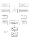
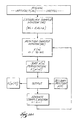
- Fig. 21 shows the time-sequential mode of operation in diagrammatic flow chart form.
- the time-sequential mode simultaneously records electrograms at first electrode sites ES(1).
- the first electrode sites ES(1) number twenty (20) and are designated E(1) to E(20).
- the electrograms for the first site electrodes E(1) to E(20) are retained for the first time interval TI(1).
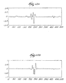
- Fig. 22A shows representative electrograms recorded at E(1) during TI(1).
- Fig. 22B shows a representative electrogram recorded at E(2) during TI(1).
- the time-sequential mode simultaneously records electrograms at second electrode sites, at least one of which is an electrode site used during the first time interval TI(1).
- Fig. 21 identifies E(1) as the common electrode site.
- E(21) to E(32) comprise the remaining electrodes in ES(2).
- Fig. 22C shows representative electrograms recorded at the common electrode site E(1) during TI(2).
- Fig. 22D shows representative electrograms recorded at the additional electrode site E(21) during TI(2).
- the time-sequential mode determines the time difference TD between the electrograms for E(1) at TI(1) and TI(2).
- Fig. 22C shows TD.
- Fig. 23C shows the representative electrograms recorded at E(1) during TI(2) after time-alignment with the electrograms recorded at E(1) during TI(1), which are shown in Fig. 23A.
- the time-sequential mode also left-shifts the electrograms E(21) through E(32) by the same amount TD.
- Fig. 23D shows the representative electrograms recorded at E(21) during TI(2) after time-alignment.
- the time-sequential mode creates the electrogram composite EC, which consists of the time-registered electrograms E(1) to E(32) taken at TI(1) and TI(2).
- the time-alignment process of creating the electrogram composite EC can be done manually by the physician, by interacting with the display device 54.
- the host processor 52 automatically analyzes the signals, computes TD, and accomplishes the time-alignment to create the composite electrogram EC.
- TD need not be computed.
- the physician or the operator can make use of any time-assignment method to align the signals based on the information contained in the common channels E(1).
- An example of useful information is the location of the maximal slopes of E(1).
- this algorithm can be automatically implemented and executed.
- the time-aligned electrogram composite EC can be analyzed in the same manner as electrograms taken simultaneously during the same time interval.
- the electrogram composite EC can be used to create the electrogram template, or to create paced electrograms for comparison with an electrogram template, or as electrograms for any other diagnostic purpose.
- signals derived from biological events can be processed, such as electrocardiograms, tissue biopotential signals, pressure waves, electrogastrograms, electromyograms, electroencephalograms, impedance measurements, and temperature measurements.
- the endocardially positioned basket structure 20 both paces and senses the resulting electrograms.
- the process controller 32 can condition the pacing module 48 in the sampling mode to pace the heart to induce a desired cardiac event, using individual or pairs of electrodes 24 on the basket structure 20 deployed in the heart region 12 (as already described), while creating templates of the resulting electrocardiograms recorded by the processing module 50 from body surface electrodes electrically coupled to the process controller 32.
- the process controller 32 paces the heart with the individual or pairs of endocardial electrodes 24 positioned on the structure 20 in the heart region 12.
- the resulting paced electrocardiograms are recorded by the same body surface electrodes (located in the same position as during the sampling mode) and compared to the electrocardiogram templates in the manner above described.
- the process controller 32 generates the location output based upon comparing the electrocardiogram sample templates with endocardially paced electrocardiograms.
- Endocardially paced electrocardiograms can also be used to identify regions of slow conduction.
- the process controller 32 conditions the pacing module 48 to pace the heart with the individual or pairs of electrodes 24 positioned on the structure 20 endocardially in the heart region 12, the resulting endocardially paced electrocardiograms are recorded by body surface electrodes coupled to the process controller 32. From the endocardially paced electrocardiograms, the process controller 32 measures the time difference between the pacing signal and the onset of the Q-wave to detect slow conduction regions (characterized by abnormally large time delays).
- the process controller 32 generates maps displaying iso-time delay regions based upon these endocardially paced electrocardiograms, to further aid in the location of the slow conduction region.
- Time delays obtained from endocardially paced electrocardiograms can also characterize heart tissue morphology.
- the body surface electrodes record electrocardiograms while the pacing module 48 paces the heart with the individual or pairs of electrodes 24 positioned on the structure 20 in the heart region 12.
- the pacing module 48 first paces the heart at or near normal sinus rhythm rates.
- the process controller 32 registers the time delays recorded from the resulting electrocardiograms.
- the pacing module 48 next paces the heart at an increased rate, e.g., at or near an arrhythmia rate.
- the process controller 32 registers the resulting time delays from the resulting electrocardiograms.
- the process controller 32 compares the paced sinus rate time delays with the paced arrhythmia rate time delay.
- the location of the pacing electrodes where the time delays shortened as the pacing rate increased are near regions of healthy tissue.
- the location of pacing electrodes where the time delays lengthened as the pacing rate increased are near regions of ischemic tissue.
- the process controller 32 preferably generates iso-display maps showing the distribution of the time delay differences, thereby aiding the physician in differentiating between regions of healthy and ischemic tissue.
- Pacing artifacts in the pacing electrograms may be eliminated by conventional techniques to better discern the initial point of depolarization.
- the process controller 32 includes a filter 56 (see Fig. 4) that removes the pacing artifact for this purpose without otherwise altering the morphology of the electrogram.
- the operation of the filter 56 may vary.
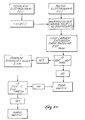
- the filter 56 implements a nonlinear sorting algorithm of the type shown in Fig. 14A.
- Fig. 14B shows a representative implementation and filter output for the algorithm in diagrammatic form.
- the algorithm establishes a sample window.
- the sample window has a predetermined length (WL), expressed in terms of the number of discrete sample points the window contains.
- the predetermined length (WL) of the sample window takes into account the length (AL) of the pacing artifact, which is expressed in terms of the number of sample points that encompass the pacing artifact.
- the window length WL is an odd number.
- WL is significantly smaller than twice AL, the sorting algorithm will not serve to eliminate the pacing artifact to the extent necessary to accurately discern the initial point of depolarization. There is, however, a limitation placed upon how large WL is relative to the size of AL. When WL is significantly larger than twice AL, the morphology of the electrogram will be distorted by being spread out with respect to time.
- the algorithm sorts the sample values X(n) in the window from smallest value to largest value.
- the algorithm outputs the sample value X(p[f]) contained in the selected sort position, which constitutes the filter output for the boxcar sample.
- the algorithm outputs X(p[f]) and advances the window forward in time one sample point.
- the algorithm repeats the sorting process, generating a filter output for each boxcar sample and advancing the window, until the entire electrogram has been processed.
- the algorithm then plots the filter outputs with respect to time, which constitutes the filtered electrogram.
- the sequence of sample values X(1 to 5) constitutes the boxcar sample.
- the algorithm sorts the sequence X(1 to 5) in increasing numerical value, or X(2) ⁇ X(1) ⁇ X(5) ⁇ X(4) ⁇ X(3).
- the algorithm establishes the sort positions p(n) based upon this permutation, or X(p(n)) X(p(1)) X(p(2)) X(p(3)) X(p(4)) X(p(5)) Value 2 4 6 8 10
- the algorithm selects a sort position p(f) according to prescribed criteria.
- the criteria for selecting the sort position takes into account the length of the artifact AL, as will be discussed later.
- the criteria specifies the sort position relative to the other sort positions.
- (f) is expressed as a position (z) of WL positions, i.e., p(z/WL), where WL is the size of the sort window.
- the position z is selected taking into account AL, and, more particularly, z should increase as AL decreases.
- p(3/5) means that X(p(3)) replaces x(3) in the output sequence.
- the value X(p(3)) is 6, which becomes the filter output for this boxcar sample, based upon the selected sort position criteria.
- p(3/5) criteria actually implements a median filter.
- the value X(p(4)) is 8, which becomes the nonlinear, non-median filter output for this boxcar sample, based upon the selected sort position criteria. This corresponds to x(4) of the output sequence.
- the algorithm advances the window one sample at a time, sorting the sample enclosed within the window, and generating a filter output based upon the sort criteria, and so on until the entire electrogram has been filtered.
- the algorithm keeps the timing of filter output in sequence with the timing of the electrogram by retaining the value of edge samples, so that the number of filter outputs equal the number of electrogram samples.
- the number of edge values retained depends upon the size of the sample window WL.
- the algorithm retains a prescribed number, y 1 , of beginning sample values a number, y 2 , of ending sample values, arranging the filter output between the prescribed number of beginning and ending sample values to keep the filter output arranged with respect to time in sequence with the derived biological signal.
- Fig. 14B shows the filtering of ten sample points (4 2 7 5 1 10 3 8 9 6) in accordance with the above described technique.
- the window length WL in Fig. 14B is 5, and the sort criteria is median filtering, i.e. p(3/5).
- Fig. 14B also shows the filter outputs (4 5 5 5 8 8) between the edge samples, with the sorted samples appearing to the right of the filter outputs.
- Fig. 14C shows the filtering of the same ten sample points (4 2 7 5 1 10 3 8 9 6), with the same window length WL of 5, but with a non-median sort criteria p(4/5).
- Fig. 14C shows the filter output for the p(4/5)-criterion: (5 7 7 8 9 9) between the edge samples.
- the selection of the sort position p(f) takes into account the morphology of the pacing artifact in terms of the length of the artifact AL, expressed in terms of the number of sample points that encompass it.
- the percentage value of f should increase as the artifact length AL decreases, or, given a constant WL, z should increase as AL decreases.
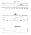
- Fig. 15A shows a simulated pacing artifact where AL is 5 and the width of the highest peak is 3.
- Fig. 15B shows the filtered output for p(2/5);
- Fig. 15C shows the filtered output for the median, or p(3/5); and
- Fig. 15D shows the filtered output for p(4/5).
- the criteria p(2/5) fully eliminated the pacing artifact (Fig. 15B), whereas the criteria p(3/5) and p(4/5) did not (Figs. 15C and 15D, respectively).
- the optimal elimination of certain pacing artifacts requires nonlinear, non-median filtering, where the position z comprises a positive integer; 1 ⁇ z ⁇ WL; and: z ⁇ [ WL + 1 2 ]
- Fig. 16A shows a simulated pacing artifact where AL is 5 and the width of the highest peak is 2.
- Fig. 16B shows the filtered output for p(2/5);
- Fig. 16C shows the filtered output for p(3/5), i.e. the median; and
- Fig. 16D shows the filtered output for p(4/5).
- the criteria p(3/5) fully eliminated the pacing artifact (Fig. 16C), whereas the criteria p(2/5) and p(4/5) did not (Figs. 16B and 16D, respectively).
- Fig. 17A shows a simulated pacing artifact where AL is 5 and the width of the highest peak is 1.
- Fig. 17B shows the filtered output for p(2/5);
- Fig. 17C shows the filtered output for p(3/5), i.e. the median; and
- Fig. 17D shows the filtered output for p(4/5).
- the criteria p(4/5) fully eliminated the pacing artifact (Fig. 17D), whereas the criteria p(2/5) and p(3/5) did not (Figs. 17B and 17C, respectively).
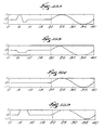
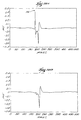
- Fig. 18A shows a paced electrogram consisting of 500 samples taken in increments of 0.5 seconds.
- Fig. 18C shows a reduction in the size but not an elimination of the pacing artifact PA by median filtering.
- Fig. 18B shows an elimination of the pacing artifact by median filtering.
- the filter 56 can implement the adaptive filtering algorithm shown in Fig. 19 to remove the pacing artifact.
- the filter 56 generates an internal variable TPACE(t) expressing a template of the pacing artifact itself.
- the function TPACE(t) preferably begins with a preestablished template typical for a pacing artifact.
- the algorithm can create an initial template by manually selecting a window about the artifact and creating a template by, for example, conventional signal averaging techniques. This template could be adaptively updated using appropriate signal averaging techniques.
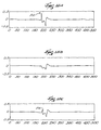
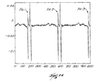
- Figs. 24 to 28 exemplify a preferred way of generating a template of the pacing artifact.
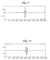
- Fig. 24 shows a portion of a recording of a paced electrogram extending over about two beats and a half.
- Fig. 24 shows three pacing pulses (PA-1; PA-2; PA-3), which are the artifacts that are to be ultimately removed.
- PA-1 pacing pulses
- PA-3 pacing pulses
- the physician preferably selects windows about each pacing pulse PA-1 to 3 to create an averaged template.
- the physician can select one of the pacing pulse, for example PA-1, to generate the template.
- Figs. 25A to C represent the signals PS-1; PS-2; and PS-3 contained by the three windows manually selected about the pacing pulses, respectively PA-1; PA-2; and PA-3.
- the physician manually aligns the three signals PS-1; PS-2; and PS-3 and truncates them at the same length, as Figs. 26A to C show.
- the three signals PS-1; PS-2; and PS-3 have been aligned about their largest positive peak, although other alignment techniques could be used.
- Fig. 27 shows the template TPACE(t) of the pacing artifact generated by averaging the three signals PS-1; PS-2; and PS-3 after alignment and truncation (i.e., the signals shown in Figs. 26A to C are averaged).
- the template TPACE(t) (Fig. 28B) is aligned with the first pacing pulse in the electrogram (Fig. 28A) prior to executing the adaptive algorithm for artifact removal.
- TPACE(t) It is not necessary to generate a new pacing artifact template TPACE(t) for the electrogram sensed by each electrode.
- the same initial template TPACE(t) from only one of the electrodes can be used for every electrogram.
- pacing signals from different electrodes can be aligned for averaging to create the template TPACE(t), which is then used for all electrograms.
- the template TPACE(t) can also be generated by approximating the pacing pulse using suitable mathematical techniques, for example, spline interpolation.
- a universal template TPACE(t) can also be generated from recordings taken from different patients at different times with different equipment, although such different records may require proper adjustment before generating the universal template TPACE(t).
- the template TPACE(t) of the filter 56 reduces IN(t), so the output signal EG(t) is expressed as IN(t) - TPACE(t).
- the filter 56 changes TPACE(t) over time based upon the energy of the output EG(t) so as to minimize the energy of (PACE(t) - TPACE(t)) over time, and therefore, the energy of EG(t).
- the filter 56 seeks to minimize the function EG(t) + PACE(t) - TPACE(t) over time. Ideally, the energy of EG(t) is minimized over time when TPACE(t) equals PACE(t), therefore being equal to the energy of EG(t).
- the filter algorithm changes TPACE(t) over time applying known iterative techniques.
- LMS Least-Mean-Squares
- the template for TPACE(t) is used as a reference input for the LMS algorithm.
- the weight vector is initialized at [K 0 0 ... 0].
- K is chosen equal to the ratio between the peak of PACE(t) and the peak of the template TPACE(t).
- PACE(t) TPACE(t)
- k is equal to one. Further details of LMS are found in "Adaptive Filter Theory" by S. Haykin (Prentice Hall, 1991)
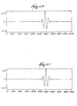
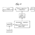
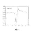
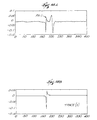
- Fig. 20A shows a representative paced electrogram.
- the designation PA in Fig. 20A marks the location of the pacing artifact.
- Fig. 20B shows the paced electrogram after filtering using the LMS technique above described.
- Fig. 20B shows the effectiveness of the adaptive filter to remove the pacing artifact, without otherwise altering the morphology of the paced electrogram.
- Either of the above described techniques for removing the pacing artifact have application outside the conditioning of the electrogram for morphology matching described herein. Either technique has application whenever it is desired to remove an artifact signal from a useful signal or to otherwise eliminate virtually any signal of a known shape.
- nonlinear filtering or adaptive filtering can be used whenever it is desired to remove cardiac related or other periodic artifacts, for example, in respiratory signals, or EEG's, or from neurological signals.
- Nonlinear filtering or adaptive filtering can also be used to eliminate periodic artifacts that are not cardiac related, for example, 50 to 60 Hz noise from sensed signals due to poor power source isolation.
- nonlinear filtering or adaptive filtering can also be used to remove the pacing artifact before measuring the level of fractionation in an electrogram. Since a pacing artifact looks much like an electrogram, it is desirable to remove it before analyzing for actual fractionation.
- nonlinear filtering or adaptive filtering can be used to remove a pacing artifact when it is desired to conduct a frequency domain analysis of the cardiac signal, to determine the regularity of the heart beat.
- any portion of the electrogram can be isolated for elimination using the filtering techniques described above, not merely the pacing artifact.
- the nonlinear and adaptive filtering techniques can be used in applications where low pass filtering cannot be used.
- body surface mapping can use low pass filtering of electrograms
- endocardial mapping cannot, due to the use of higher frequencies than in electrocardiograms.
- a common electrocardiogram frequency spectrum is .05 to 100 Hz
- a common bipolar electrogram spectrum is 1 to 300 Hz.
- Nonlinear filtering or adaptive filtered can be used for processing or analyzing virtually any signal derived from a biological event.
- nonlinear filter or adaptive filtering can be used to process or analyze electroencephalograms, respiratory signals, electrogastrograms, and electromyograms.
Landscapes
- Health & Medical Sciences (AREA)
- Life Sciences & Earth Sciences (AREA)
- Heart & Thoracic Surgery (AREA)
- General Health & Medical Sciences (AREA)
- Animal Behavior & Ethology (AREA)
- Engineering & Computer Science (AREA)
- Biomedical Technology (AREA)
- Veterinary Medicine (AREA)
- Public Health (AREA)
- Molecular Biology (AREA)
- Surgery (AREA)
- Pathology (AREA)
- Physics & Mathematics (AREA)
- Medical Informatics (AREA)
- Biophysics (AREA)
- Cardiology (AREA)
- Physiology (AREA)
- Vascular Medicine (AREA)
- Nuclear Medicine, Radiotherapy & Molecular Imaging (AREA)
- Radiology & Medical Imaging (AREA)
- Electrotherapy Devices (AREA)
- Apparatus For Radiation Diagnosis (AREA)
- Surgical Instruments (AREA)
- Polishing Bodies And Polishing Tools (AREA)
- Measurement And Recording Of Electrical Phenomena And Electrical Characteristics Of The Living Body (AREA)
Abstract
Description

where N equals the number of local extremes to the left of EXCMAX (which is also equal to the number of local extremes situated to the right of EXCMAX (see Fig. 7B).
| X(n) | X(1) | X(2) | X(3) | X(4) | X(5) |
| Value | 4 | 2 | 10 | 8 | 6 |
| X(p(n)) | X(p(1)) | X(p(2)) | X(p(3)) | X(p(4)) | X(p(5)) |
| Value | 2 | 4 | 6 | 8 | 10 |
the expression:
Claims (13)
- A system (10) for examining heart tissue, comprising an array of multiple electrodes (24) supported for operative association with a region of heart tissue, a roving electrode (68) supported for movement relative to the multiple electrodes (24) for operative association with selected, different regions of endocardial tissue within the heart, and an analog or digital processing element (32) coupled to the multiple electrodes (24), characterized in that
the processing element also is coupled to the roving electrode (68) for conditioning a first of the multiple electrodes (24) and the roving electrode (68) to emit a pacing signal while a second of the multiple electrodes (24) and the roving electrode (68) records paced electrograms occurring as a result of the pacing signal. - A system according to claim 1, wherein the analog or digital processing element (32) is configured for processing the paced electrograms.
- A system according to claim 1, wherein the analog and digital processing element (32) is configured for:conditioning the multiple electrodes (24) to sense a sample of biopotentials occurring during a cardiac event of known diagnosis and for creating a template based upon the sensed biopotential sample,conditioning either one of the multiple electrodes (24) or the remote electrode to emit a pacing signal and to sense with the multiple electrodes (24) a sample of the paced biopotentials occurring as a result of the pacing signal, andelectronically comparing the paced biopotential sample to the template and generating an output based upon the comparison.
- A system according to claim 3,wherein the sensed biopotential sample of the template comprises an electrogram of a first predetermined duration, andwherein the sensed paced biopotential sample comprises an electrogram of a second predetermined duration not shorter than the first predetermined duration.
- A system according to claim 4, wherein the first and second predetermined durations are equal.
- A system according to claim 5, wherein the first and second predetermined durations comprise one heart beat.
- A system according to any preceding claim, wherein the multiple electrode array (24) assumes a radially expanded position in operative association with the region of endocardial tissue.
- A system according to any preceding claim, wherein the roving electrode (68) is remotely steerable.
- A system according to claim 3, wherein the output comprises a matching coefficient indicating how alike the biopotential sample is to the template.
- A system according to claim 3, wherein the biopotential sample and the template are compared by matched filtering.
- A system according to claim 3, wherein the biopotential sample and the template are compared by cross correlation.
- A system according to claim 3, wherein the biopotential sample and the template are compared by deriving a norm of the difference.
- A system according to claim 3, wherein the biopotential sample and the template are compared by using the template to create a matched filtered sample and by analyzing the symmetry of the matched filtered sample.
Applications Claiming Priority (3)
| Application Number | Priority Date | Filing Date | Title |
|---|---|---|---|
| US390383 | 1995-02-17 | ||
| US08/390,383 US5595183A (en) | 1995-02-17 | 1995-02-17 | Systems and methods for examining heart tissue employing multiple electrode structures and roving electrodes |
| PCT/US1996/002190 WO1996025097A1 (en) | 1995-02-17 | 1996-02-16 | Systems and methods for examining heart tissue |
Publications (3)
| Publication Number | Publication Date |
|---|---|
| EP0809464A1 EP0809464A1 (en) | 1997-12-03 |
| EP0809464A4 EP0809464A4 (en) | 1999-01-07 |
| EP0809464B1 true EP0809464B1 (en) | 2001-06-13 |
Family
ID=23542257
Family Applications (1)
| Application Number | Title | Priority Date | Filing Date |
|---|---|---|---|
| EP96906520A Expired - Lifetime EP0809464B1 (en) | 1995-02-17 | 1996-02-16 | System for examining heart tissue |
Country Status (8)
| Country | Link |
|---|---|
| US (1) | US5595183A (en) |
| EP (1) | EP0809464B1 (en) |
| JP (1) | JP3677780B2 (en) |
| AT (1) | ATE201974T1 (en) |
| CA (1) | CA2213216C (en) |
| DE (1) | DE69613350T2 (en) |
| ES (1) | ES2159725T3 (en) |
| WO (1) | WO1996025097A1 (en) |
Families Citing this family (263)
| Publication number | Priority date | Publication date | Assignee | Title |
|---|---|---|---|---|
| US5324284A (en) * | 1992-06-05 | 1994-06-28 | Cardiac Pathways, Inc. | Endocardial mapping and ablation system utilizing a separately controlled ablation catheter and method |
| US6161543A (en) | 1993-02-22 | 2000-12-19 | Epicor, Inc. | Methods of epicardial ablation for creating a lesion around the pulmonary veins |
| IL116699A (en) | 1996-01-08 | 2001-09-13 | Biosense Ltd | Method of constructing cardiac map |
| US5921924A (en) * | 1993-12-03 | 1999-07-13 | Avitall; Boaz | Mapping and ablation catheter system utilizing multiple control elements |
| US6405732B1 (en) * | 1994-06-24 | 2002-06-18 | Curon Medical, Inc. | Method to treat gastric reflux via the detection and ablation of gastro-esophageal nerves and receptors |
| US6101409A (en) * | 1995-02-17 | 2000-08-08 | Ep Technologies, Inc. | Systems and methods for analyzing biopotential morphologies in body tissue |
| US5711305A (en) * | 1995-02-17 | 1998-01-27 | Ep Technologies, Inc. | Systems and methods for acquiring endocardially or epicardially paced electrocardiograms |
| US5897553A (en) | 1995-11-02 | 1999-04-27 | Medtronic, Inc. | Ball point fluid-assisted electrocautery device |
| US6409722B1 (en) | 1998-07-07 | 2002-06-25 | Medtronic, Inc. | Apparatus and method for creating, maintaining, and controlling a virtual electrode used for the ablation of tissue |
| US5853364A (en) * | 1995-08-07 | 1998-12-29 | Nellcor Puritan Bennett, Inc. | Method and apparatus for estimating physiological parameters using model-based adaptive filtering |
| NL1003024C2 (en) * | 1996-05-03 | 1997-11-06 | Tjong Hauw Sie | Stimulus conduction blocking instrument. |
| US5842998A (en) * | 1996-08-21 | 1998-12-01 | Cleveland Clinic Foundation | Apparatus for determining the conductivity of blood |
| US8353908B2 (en) | 1996-09-20 | 2013-01-15 | Novasys Medical, Inc. | Treatment of tissue in sphincters, sinuses, and orifices |
| US6311692B1 (en) * | 1996-10-22 | 2001-11-06 | Epicor, Inc. | Apparatus and method for diagnosis and therapy of electrophysiological disease |
| US7052493B2 (en) * | 1996-10-22 | 2006-05-30 | Epicor Medical, Inc. | Methods and devices for ablation |
| US6840936B2 (en) * | 1996-10-22 | 2005-01-11 | Epicor Medical, Inc. | Methods and devices for ablation |
| US6805128B1 (en) | 1996-10-22 | 2004-10-19 | Epicor Medical, Inc. | Apparatus and method for ablating tissue |
| US6719755B2 (en) * | 1996-10-22 | 2004-04-13 | Epicor Medical, Inc. | Methods and devices for ablation |
| CA2273149A1 (en) * | 1996-12-02 | 1998-06-11 | Angiotrax, Inc. | Apparatus and methods for percutaneously performing surgery |
| US6120520A (en) | 1997-05-27 | 2000-09-19 | Angiotrax, Inc. | Apparatus and methods for stimulating revascularization and/or tissue growth |
| US6051008A (en) | 1996-12-02 | 2000-04-18 | Angiotrax, Inc. | Apparatus having stabilization members for percutaneously performing surgery and methods of use |
| US6102926A (en) | 1996-12-02 | 2000-08-15 | Angiotrax, Inc. | Apparatus for percutaneously performing myocardial revascularization having means for sensing tissue parameters and methods of use |
| US5916163A (en) * | 1997-03-07 | 1999-06-29 | Ep Technologies, Inc. | Graphical user interface for use with multiple electrode catheters |
| US5954661A (en) * | 1997-03-31 | 1999-09-21 | Thomas Jefferson University | Tissue characterization and treatment using pacing |
| US6088614A (en) * | 1997-03-31 | 2000-07-11 | Boston Scientific Corporation | Tissue characterization to identify an ablation site |
| US5972026A (en) | 1997-04-07 | 1999-10-26 | Broncus Technologies, Inc. | Bronchial stenter having diametrically adjustable electrodes |
| US7027869B2 (en) | 1998-01-07 | 2006-04-11 | Asthmatx, Inc. | Method for treating an asthma attack |
| US6200333B1 (en) | 1997-04-07 | 2001-03-13 | Broncus Technologies, Inc. | Bronchial stenter |
| US6634363B1 (en) | 1997-04-07 | 2003-10-21 | Broncus Technologies, Inc. | Methods of treating lungs having reversible obstructive pulmonary disease |
| US7992572B2 (en) | 1998-06-10 | 2011-08-09 | Asthmatx, Inc. | Methods of evaluating individuals having reversible obstructive pulmonary disease |
| US7425212B1 (en) | 1998-06-10 | 2008-09-16 | Asthmatx, Inc. | Devices for modification of airways by transfer of energy |
| US6488673B1 (en) | 1997-04-07 | 2002-12-03 | Broncus Technologies, Inc. | Method of increasing gas exchange of a lung |
| US6273907B1 (en) | 1997-04-07 | 2001-08-14 | Broncus Technologies, Inc. | Bronchial stenter |
| US6411852B1 (en) | 1997-04-07 | 2002-06-25 | Broncus Technologies, Inc. | Modification of airways by application of energy |
| US6283988B1 (en) | 1997-04-07 | 2001-09-04 | Broncus Technologies, Inc. | Bronchial stenter having expandable electrodes |
| US6096037A (en) * | 1997-07-29 | 2000-08-01 | Medtronic, Inc. | Tissue sealing electrosurgery device and methods of sealing tissue |
| US6014579A (en) * | 1997-07-21 | 2000-01-11 | Cardiac Pathways Corp. | Endocardial mapping catheter with movable electrode |
| US9023031B2 (en) * | 1997-08-13 | 2015-05-05 | Verathon Inc. | Noninvasive devices, methods, and systems for modifying tissues |
| US8709007B2 (en) | 1997-10-15 | 2014-04-29 | St. Jude Medical, Atrial Fibrillation Division, Inc. | Devices and methods for ablating cardiac tissue |
| US7921855B2 (en) * | 1998-01-07 | 2011-04-12 | Asthmatx, Inc. | Method for treating an asthma attack |
| US7165551B2 (en) * | 1998-02-19 | 2007-01-23 | Curon Medical, Inc. | Apparatus to detect and treat aberrant myoelectric activity |
| US20100114087A1 (en) * | 1998-02-19 | 2010-05-06 | Edwards Stuart D | Methods and devices for treating urinary incontinence |
| US6115626A (en) * | 1998-03-26 | 2000-09-05 | Scimed Life Systems, Inc. | Systems and methods using annotated images for controlling the use of diagnostic or therapeutic instruments in instruments in interior body regions |
| US6527767B2 (en) | 1998-05-20 | 2003-03-04 | New England Medical Center | Cardiac ablation system and method for treatment of cardiac arrhythmias and transmyocardial revascularization |
| US20070123958A1 (en) * | 1998-06-10 | 2007-05-31 | Asthmatx, Inc. | Apparatus for treating airways in the lung |
| US8181656B2 (en) | 1998-06-10 | 2012-05-22 | Asthmatx, Inc. | Methods for treating airways |
| US7198635B2 (en) | 2000-10-17 | 2007-04-03 | Asthmatx, Inc. | Modification of airways by application of energy |
| US6537248B2 (en) | 1998-07-07 | 2003-03-25 | Medtronic, Inc. | Helical needle apparatus for creating a virtual electrode used for the ablation of tissue |
| US6706039B2 (en) | 1998-07-07 | 2004-03-16 | Medtronic, Inc. | Method and apparatus for creating a bi-polar virtual electrode used for the ablation of tissue |
| US6301496B1 (en) | 1998-07-24 | 2001-10-09 | Biosense, Inc. | Vector mapping of three-dimensionally reconstructed intrabody organs and method of display |
| US6226542B1 (en) | 1998-07-24 | 2001-05-01 | Biosense, Inc. | Three-dimensional reconstruction of intrabody organs |
| US8308719B2 (en) * | 1998-09-21 | 2012-11-13 | St. Jude Medical, Atrial Fibrillation Division, Inc. | Apparatus and method for ablating tissue |
| US20070282324A1 (en) * | 1999-07-19 | 2007-12-06 | Matthias Vaska | Apparatus and method for diagnosis and therapy of electrophysiological disease |
| EP1207788A4 (en) * | 1999-07-19 | 2009-12-09 | St Jude Medical Atrial Fibrill | FABRIC ABLATION TECHNIQUES AND CORRESPONDING DEVICE |
| JP3213602B2 (en) * | 1999-07-27 | 2001-10-02 | 笠貫 宏 | Intracardiac potential analyzer and method |
| US6368285B1 (en) | 1999-09-21 | 2002-04-09 | Biosense, Inc. | Method and apparatus for mapping a chamber of a heart |
| US6385476B1 (en) | 1999-09-21 | 2002-05-07 | Biosense, Inc. | Method and apparatus for intracardially surveying a condition of a chamber of a heart |
| US6546271B1 (en) | 1999-10-01 | 2003-04-08 | Bioscience, Inc. | Vascular reconstruction |
| US6645199B1 (en) * | 1999-11-22 | 2003-11-11 | Scimed Life Systems, Inc. | Loop structures for supporting diagnostic and therapeutic elements contact with body tissue and expandable push devices for use with same |
| US6529756B1 (en) * | 1999-11-22 | 2003-03-04 | Scimed Life Systems, Inc. | Apparatus for mapping and coagulating soft tissue in or around body orifices |
| US7706882B2 (en) * | 2000-01-19 | 2010-04-27 | Medtronic, Inc. | Methods of using high intensity focused ultrasound to form an ablated tissue area |
| US8221402B2 (en) * | 2000-01-19 | 2012-07-17 | Medtronic, Inc. | Method for guiding a medical device |
| US6447443B1 (en) * | 2001-01-13 | 2002-09-10 | Medtronic, Inc. | Method for organ positioning and stabilization |
| US6692450B1 (en) * | 2000-01-19 | 2004-02-17 | Medtronic Xomed, Inc. | Focused ultrasound ablation devices having selectively actuatable ultrasound emitting elements and methods of using the same |
| US6595934B1 (en) * | 2000-01-19 | 2003-07-22 | Medtronic Xomed, Inc. | Methods of skin rejuvenation using high intensity focused ultrasound to form an ablated tissue area containing a plurality of lesions |
| US6892091B1 (en) | 2000-02-18 | 2005-05-10 | Biosense, Inc. | Catheter, method and apparatus for generating an electrical map of a chamber of the heart |
| US8048070B2 (en) | 2000-03-06 | 2011-11-01 | Salient Surgical Technologies, Inc. | Fluid-assisted medical devices, systems and methods |
| US6760620B2 (en) | 2000-03-15 | 2004-07-06 | Resolution Medical, Inc. | Non-invasive localization and treatment of focal atrial fibrillation |
| US8251070B2 (en) | 2000-03-27 | 2012-08-28 | Asthmatx, Inc. | Methods for treating airways |
| US20020107514A1 (en) * | 2000-04-27 | 2002-08-08 | Hooven Michael D. | Transmural ablation device with parallel jaws |
| US6514250B1 (en) * | 2000-04-27 | 2003-02-04 | Medtronic, Inc. | Suction stabilized epicardial ablation devices |
| US6932811B2 (en) | 2000-04-27 | 2005-08-23 | Atricure, Inc. | Transmural ablation device with integral EKG sensor |
| AU2001249874A1 (en) * | 2000-04-27 | 2001-11-12 | Medtronic, Inc. | System and method for assessing transmurality of ablation lesions |
| US6488680B1 (en) | 2000-04-27 | 2002-12-03 | Medtronic, Inc. | Variable length electrodes for delivery of irrigated ablation |
| US6546935B2 (en) | 2000-04-27 | 2003-04-15 | Atricure, Inc. | Method for transmural ablation |
| US6905498B2 (en) | 2000-04-27 | 2005-06-14 | Atricure Inc. | Transmural ablation device with EKG sensor and pacing electrode |
| DE60111517T2 (en) * | 2000-04-27 | 2006-05-11 | Medtronic, Inc., Minneapolis | VIBRATION-SENSITIVE ABLATION DEVICE |
| US6837886B2 (en) * | 2000-05-03 | 2005-01-04 | C.R. Bard, Inc. | Apparatus and methods for mapping and ablation in electrophysiology procedures |
| US6400981B1 (en) | 2000-06-21 | 2002-06-04 | Biosense, Inc. | Rapid mapping of electrical activity in the heart |
| US6650927B1 (en) | 2000-08-18 | 2003-11-18 | Biosense, Inc. | Rendering of diagnostic imaging data on a three-dimensional map |
| US6633773B1 (en) | 2000-09-29 | 2003-10-14 | Biosene, Inc. | Area of interest reconstruction for surface of an organ using location data |
| US7306591B2 (en) | 2000-10-02 | 2007-12-11 | Novasys Medical, Inc. | Apparatus and methods for treating female urinary incontinence |
| US6640120B1 (en) | 2000-10-05 | 2003-10-28 | Scimed Life Systems, Inc. | Probe assembly for mapping and ablating pulmonary vein tissue and method of using same |
| US6926669B1 (en) | 2000-10-10 | 2005-08-09 | Medtronic, Inc. | Heart wall ablation/mapping catheter and method |
| US7104987B2 (en) | 2000-10-17 | 2006-09-12 | Asthmatx, Inc. | Control system and process for application of energy to airway walls and other mediums |
| US6475179B1 (en) | 2000-11-10 | 2002-11-05 | New England Medical Center | Tissue folding device for tissue ablation, and method thereof |
| US7628780B2 (en) * | 2001-01-13 | 2009-12-08 | Medtronic, Inc. | Devices and methods for interstitial injection of biologic agents into tissue |
| US20040138621A1 (en) | 2003-01-14 | 2004-07-15 | Jahns Scott E. | Devices and methods for interstitial injection of biologic agents into tissue |
| US7740623B2 (en) * | 2001-01-13 | 2010-06-22 | Medtronic, Inc. | Devices and methods for interstitial injection of biologic agents into tissue |
| US7959626B2 (en) | 2001-04-26 | 2011-06-14 | Medtronic, Inc. | Transmural ablation systems and methods |
| US6807968B2 (en) * | 2001-04-26 | 2004-10-26 | Medtronic, Inc. | Method and system for treatment of atrial tachyarrhythmias |
| US6699240B2 (en) * | 2001-04-26 | 2004-03-02 | Medtronic, Inc. | Method and apparatus for tissue ablation |
| US6663627B2 (en) | 2001-04-26 | 2003-12-16 | Medtronic, Inc. | Ablation system and method of use |
| US6648883B2 (en) * | 2001-04-26 | 2003-11-18 | Medtronic, Inc. | Ablation system and method of use |
| US7250048B2 (en) | 2001-04-26 | 2007-07-31 | Medtronic, Inc. | Ablation system and method of use |
| EP1435867B1 (en) | 2001-09-05 | 2010-11-17 | Salient Surgical Technologies, Inc. | Fluid-assisted medical devices and systems |
| US6895267B2 (en) | 2001-10-24 | 2005-05-17 | Scimed Life Systems, Inc. | Systems and methods for guiding and locating functional elements on medical devices positioned in a body |
| US6656175B2 (en) * | 2001-12-11 | 2003-12-02 | Medtronic, Inc. | Method and system for treatment of atrial tachyarrhythmias |
| KR100580618B1 (en) * | 2002-01-23 | 2006-05-16 | 삼성전자주식회사 | Apparatus and method for recognizing user emotion through short time monitoring of physiological signals |
| US7967816B2 (en) * | 2002-01-25 | 2011-06-28 | Medtronic, Inc. | Fluid-assisted electrosurgical instrument with shapeable electrode |
| US6827715B2 (en) * | 2002-01-25 | 2004-12-07 | Medtronic, Inc. | System and method of performing an electrosurgical procedure |
| US20080275439A1 (en) * | 2002-01-25 | 2008-11-06 | David Francischelli | Cardiac ablation and electrical interface system and instrument |
| US7311705B2 (en) * | 2002-02-05 | 2007-12-25 | Medtronic, Inc. | Catheter apparatus for treatment of heart arrhythmia |
| US7653438B2 (en) | 2002-04-08 | 2010-01-26 | Ardian, Inc. | Methods and apparatus for renal neuromodulation |
| US7118566B2 (en) | 2002-05-16 | 2006-10-10 | Medtronic, Inc. | Device and method for needle-less interstitial injection of fluid for ablation of cardiac tissue |
| US7294143B2 (en) * | 2002-05-16 | 2007-11-13 | Medtronic, Inc. | Device and method for ablation of cardiac tissue |
| US7291161B2 (en) | 2002-10-02 | 2007-11-06 | Atricure, Inc. | Articulated clamping member |
| US20040082947A1 (en) * | 2002-10-25 | 2004-04-29 | The Regents Of The University Of Michigan | Ablation catheters |
| US20050033137A1 (en) * | 2002-10-25 | 2005-02-10 | The Regents Of The University Of Michigan | Ablation catheters and methods for their use |
| US7083620B2 (en) | 2002-10-30 | 2006-08-01 | Medtronic, Inc. | Electrosurgical hemostat |
| WO2006020920A2 (en) * | 2003-01-29 | 2006-02-23 | Medtronic, Inc. | Catheter apparatus for treatment of heart arrhythmia |
| US7288092B2 (en) | 2003-04-23 | 2007-10-30 | Atricure, Inc. | Method and apparatus for ablating cardiac tissue with guide facility |
| US7497857B2 (en) * | 2003-04-29 | 2009-03-03 | Medtronic, Inc. | Endocardial dispersive electrode for use with a monopolar RF ablation pen |
| US20040226556A1 (en) | 2003-05-13 | 2004-11-18 | Deem Mark E. | Apparatus for treating asthma using neurotoxin |
| US20050187545A1 (en) * | 2004-02-20 | 2005-08-25 | Hooven Michael D. | Magnetic catheter ablation device and method |
| US7530980B2 (en) * | 2004-04-14 | 2009-05-12 | Atricure, Inc | Bipolar transmural ablation method and apparatus |
| US8333764B2 (en) * | 2004-05-12 | 2012-12-18 | Medtronic, Inc. | Device and method for determining tissue thickness and creating cardiac ablation lesions |
| ATE547990T1 (en) * | 2004-05-14 | 2012-03-15 | Medtronic Inc | DEVICES FOR TREATING AFRICIA BY MASS ABLATION |
| EP1761186B1 (en) | 2004-05-17 | 2016-01-06 | Boston Scientific Scimed, Inc. | Apparatus for mapping and/or ablation of cardiac tissue |
| US20050288599A1 (en) * | 2004-05-17 | 2005-12-29 | C.R. Bard, Inc. | High density atrial fibrillation cycle length (AFCL) detection and mapping system |
| EP1750607A2 (en) * | 2004-06-02 | 2007-02-14 | Medtronic, Inc. | Loop ablation apparatus and method |
| US20100145331A1 (en) * | 2004-06-02 | 2010-06-10 | Chrisitian Steven C | Loop Ablation Apparatus and Method |
| EP1750606B1 (en) * | 2004-06-02 | 2010-05-05 | Medtronic, Inc. | Compound bipolar ablation device |
| EP1761188B1 (en) * | 2004-06-02 | 2011-07-20 | Medtronic, Inc. | Clamping ablation tool |
| WO2005120376A2 (en) | 2004-06-02 | 2005-12-22 | Medtronic, Inc. | Ablation device with jaws |
| US8663245B2 (en) | 2004-06-18 | 2014-03-04 | Medtronic, Inc. | Device for occlusion of a left atrial appendage |
| WO2006009729A2 (en) * | 2004-06-18 | 2006-01-26 | Medtronic, Inc. | Methods and devices for occlusion of an atrial appendage |
| US8926635B2 (en) * | 2004-06-18 | 2015-01-06 | Medtronic, Inc. | Methods and devices for occlusion of an atrial appendage |
| US8409219B2 (en) * | 2004-06-18 | 2013-04-02 | Medtronic, Inc. | Method and system for placement of electrical lead inside heart |
| US20060089637A1 (en) | 2004-10-14 | 2006-04-27 | Werneth Randell L | Ablation catheter |
| WO2006052940A2 (en) | 2004-11-05 | 2006-05-18 | Asthmatx, Inc. | Medical device with procedure improvement features |
| US7949407B2 (en) | 2004-11-05 | 2011-05-24 | Asthmatx, Inc. | Energy delivery devices and methods |
| US20070093802A1 (en) * | 2005-10-21 | 2007-04-26 | Danek Christopher J | Energy delivery devices and methods |
| US8617152B2 (en) * | 2004-11-15 | 2013-12-31 | Medtronic Ablation Frontiers Llc | Ablation system with feedback |
| US7429261B2 (en) * | 2004-11-24 | 2008-09-30 | Ablation Frontiers, Inc. | Atrial ablation catheter and method of use |
| US7468062B2 (en) * | 2004-11-24 | 2008-12-23 | Ablation Frontiers, Inc. | Atrial ablation catheter adapted for treatment of septal wall arrhythmogenic foci and method of use |
| US20060270900A1 (en) * | 2005-05-26 | 2006-11-30 | Chin Albert K | Apparatus and methods for performing ablation |
| US8932208B2 (en) * | 2005-05-26 | 2015-01-13 | Maquet Cardiovascular Llc | Apparatus and methods for performing minimally-invasive surgical procedures |
| EP2759276A1 (en) * | 2005-06-20 | 2014-07-30 | Medtronic Ablation Frontiers LLC | Ablation catheter |
| AU2006268238A1 (en) | 2005-07-11 | 2007-01-18 | Medtronic Ablation Frontiers Llc | Low power tissue ablation system |
| US8657814B2 (en) * | 2005-08-22 | 2014-02-25 | Medtronic Ablation Frontiers Llc | User interface for tissue ablation system |
| US20070185479A1 (en) * | 2006-02-06 | 2007-08-09 | Liming Lau | Methods and devices for performing ablation and assessing efficacy thereof |
| US20070225697A1 (en) * | 2006-03-23 | 2007-09-27 | Ketan Shroff | Apparatus and methods for cardiac ablation |
| WO2007140331A2 (en) | 2006-05-25 | 2007-12-06 | Medtronic, Inc. | Methods of using high intensity focused ultrasound to form an ablated tissue area containing a plurality of lesions |
| WO2008014629A2 (en) | 2006-08-03 | 2008-02-07 | Christoph Scharf | Method and device for determining and presenting surface charge and dipole densities on cardiac walls |
| US20080039879A1 (en) * | 2006-08-09 | 2008-02-14 | Chin Albert K | Devices and methods for atrial appendage exclusion |
| US7931647B2 (en) * | 2006-10-20 | 2011-04-26 | Asthmatx, Inc. | Method of delivering energy to a lung airway using markers |
| US9757036B2 (en) | 2007-05-08 | 2017-09-12 | Mediguide Ltd. | Method for producing an electrophysiological map of the heart |
| WO2008136008A2 (en) * | 2007-05-08 | 2008-11-13 | Mediguide Ltd. | Method for producing an electrophysiological map of the heart |
| US8641704B2 (en) | 2007-05-11 | 2014-02-04 | Medtronic Ablation Frontiers Llc | Ablation therapy system and method for treating continuous atrial fibrillation |
| US8235983B2 (en) * | 2007-07-12 | 2012-08-07 | Asthmatx, Inc. | Systems and methods for delivering energy to passageways in a patient |
| US20090043301A1 (en) * | 2007-08-09 | 2009-02-12 | Asthmatx, Inc. | Monopolar energy delivery devices and methods for controlling current density in tissue |
| JP2010540160A (en) | 2007-10-05 | 2010-12-24 | マッケ カーディオバスキュラー,エルエルシー | Apparatus and method for minimally invasive surgical procedures |
| US8906011B2 (en) * | 2007-11-16 | 2014-12-09 | Kardium Inc. | Medical device for use in bodily lumens, for example an atrium |
| US8882756B2 (en) * | 2007-12-28 | 2014-11-11 | Medtronic Advanced Energy Llc | Fluid-assisted electrosurgical devices, methods and systems |
| EP2737849A3 (en) | 2008-01-17 | 2014-10-29 | Christoph Scharf | A device and method for the geometric determination of electrical dipole densities on the cardiac wall |
| US8483831B1 (en) | 2008-02-15 | 2013-07-09 | Holaira, Inc. | System and method for bronchial dilation |
| US20090209986A1 (en) * | 2008-02-15 | 2009-08-20 | Stewart Michael C | Devices, Tools and Methods for Atrial Appendage Exclusion |
| KR101719824B1 (en) | 2008-05-09 | 2017-04-04 | 호라이라 인코포레이티드 | Systems, assemblies, and methods for treating a bronchial tree |
| US8821488B2 (en) * | 2008-05-13 | 2014-09-02 | Medtronic, Inc. | Tissue lesion evaluation |
| US9254168B2 (en) * | 2009-02-02 | 2016-02-09 | Medtronic Advanced Energy Llc | Electro-thermotherapy of tissue using penetrating microelectrode array |
| JP5592409B2 (en) | 2009-02-23 | 2014-09-17 | サリエント・サージカル・テクノロジーズ・インコーポレーテッド | Fluid-assisted electrosurgical device and method of use thereof |
| US20120165684A1 (en) * | 2009-05-13 | 2012-06-28 | Monitoring Information Technologies, Inc. | Systems and Methods for Heart and Activity Monitoring |
| EP2475320B1 (en) | 2009-09-08 | 2018-02-21 | Salient Surgical Technologies, Inc. | Cartridge assembly for electrosurgical devices and corresponding electrosurgical unit |
| CN107049479B (en) | 2009-10-27 | 2020-10-16 | 努瓦拉公司 | Delivery device with coolable energy emitting assembly |
| US8911439B2 (en) | 2009-11-11 | 2014-12-16 | Holaira, Inc. | Non-invasive and minimally invasive denervation methods and systems for performing the same |
| CN106618731B (en) | 2009-11-11 | 2020-08-07 | 努瓦拉公司 | Systems, devices and methods for treating tissue and controlling stenosis |
| EP2544616B1 (en) | 2010-03-11 | 2017-09-06 | Medtronic Advanced Energy LLC | Bipolar electrosurgical cutter with position insensitive return electrode contact |
| US20110295249A1 (en) * | 2010-05-28 | 2011-12-01 | Salient Surgical Technologies, Inc. | Fluid-Assisted Electrosurgical Devices, and Methods of Manufacture Thereof |
| US9138289B2 (en) | 2010-06-28 | 2015-09-22 | Medtronic Advanced Energy Llc | Electrode sheath for electrosurgical device |
| US8906012B2 (en) | 2010-06-30 | 2014-12-09 | Medtronic Advanced Energy Llc | Electrosurgical devices with wire electrode |
| US8920417B2 (en) | 2010-06-30 | 2014-12-30 | Medtronic Advanced Energy Llc | Electrosurgical devices and methods of use thereof |
| CN101933803B (en) * | 2010-08-19 | 2012-06-27 | 复旦大学 | Cardiac mapping signal analyzing and processing device and method |
| US9023040B2 (en) | 2010-10-26 | 2015-05-05 | Medtronic Advanced Energy Llc | Electrosurgical cutting devices |
| US9480525B2 (en) | 2011-01-21 | 2016-11-01 | Kardium, Inc. | High-density electrode-based medical device system |
| US11259867B2 (en) | 2011-01-21 | 2022-03-01 | Kardium Inc. | High-density electrode-based medical device system |
| CA2764494A1 (en) | 2011-01-21 | 2012-07-21 | Kardium Inc. | Enhanced medical device for use in bodily cavities, for example an atrium |
| US9452016B2 (en) | 2011-01-21 | 2016-09-27 | Kardium Inc. | Catheter system |
| US9757044B2 (en) | 2011-03-10 | 2017-09-12 | Acutus Medical, Inc. | Device and method for the geometric determination of electrical dipole densities on the cardiac wall |
| US9427281B2 (en) | 2011-03-11 | 2016-08-30 | Medtronic Advanced Energy Llc | Bronchoscope-compatible catheter provided with electrosurgical device |
| US9750565B2 (en) | 2011-09-30 | 2017-09-05 | Medtronic Advanced Energy Llc | Electrosurgical balloons |
| US8870864B2 (en) | 2011-10-28 | 2014-10-28 | Medtronic Advanced Energy Llc | Single instrument electrosurgery apparatus and its method of use |
| US8403927B1 (en) | 2012-04-05 | 2013-03-26 | William Bruce Shingleton | Vasectomy devices and methods |
| US9770293B2 (en) | 2012-06-04 | 2017-09-26 | Boston Scientific Scimed, Inc. | Systems and methods for treating tissue of a passageway within a body |
| US9226792B2 (en) | 2012-06-12 | 2016-01-05 | Medtronic Advanced Energy Llc | Debridement device and method |
| US9592086B2 (en) | 2012-07-24 | 2017-03-14 | Boston Scientific Scimed, Inc. | Electrodes for tissue treatment |
| CA2881457C (en) | 2012-08-31 | 2021-10-26 | Acutus Medical, Inc. | Catheter system and methods of medical uses of same, including diagnostic and treatment uses for the heart |
| US11234760B2 (en) | 2012-10-05 | 2022-02-01 | Medtronic Advanced Energy Llc | Electrosurgical device for cutting and removing tissue |
| US20140121657A1 (en) * | 2012-10-26 | 2014-05-01 | Biosense Webster (Israel) Ltd. | Irrrigated ablation catheter with deformable head |
| US9272132B2 (en) | 2012-11-02 | 2016-03-01 | Boston Scientific Scimed, Inc. | Medical device for treating airways and related methods of use |
| WO2014071372A1 (en) | 2012-11-05 | 2014-05-08 | Boston Scientific Scimed, Inc. | Devices for delivering energy to body lumens |
| US9398933B2 (en) | 2012-12-27 | 2016-07-26 | Holaira, Inc. | Methods for improving drug efficacy including a combination of drug administration and nerve modulation |
| CN105358070B (en) | 2013-02-08 | 2018-03-23 | 阿库图森医疗有限公司 | Expandable catheter assembly with flexible printed circuit board |
| US9814618B2 (en) | 2013-06-06 | 2017-11-14 | Boston Scientific Scimed, Inc. | Devices for delivering energy and related methods of use |
| CA2913220A1 (en) | 2013-08-09 | 2015-02-12 | Boston Scientific Scimed, Inc. | Expandable catheter and related methods of manufacture and use |
| US10828011B2 (en) | 2013-09-13 | 2020-11-10 | Acutus Medical, Inc. | Devices and methods for determination of electrical dipole densities on a cardiac surface |
| WO2015066164A1 (en) | 2013-10-31 | 2015-05-07 | Boston Scientific Scimed, Inc. | Medical device for high resolution mapping using localized matching |
| CN105636514B (en) | 2013-11-01 | 2020-06-05 | 波士顿科学医学有限公司 | Cardiac Mapping Using Delay Interpolation |
| US10314647B2 (en) | 2013-12-23 | 2019-06-11 | Medtronic Advanced Energy Llc | Electrosurgical cutting instrument |
| US10813686B2 (en) | 2014-02-26 | 2020-10-27 | Medtronic Advanced Energy Llc | Electrosurgical cutting instrument |
| JP2017506572A (en) | 2014-03-07 | 2017-03-09 | ボストン サイエンティフィック サイムド,インコーポレイテッドBoston Scientific Scimed,Inc. | Medical device for mapping heart tissue |
| WO2015138167A1 (en) | 2014-03-11 | 2015-09-17 | Boston Scientific Scimed, Inc. | Medical devices for mapping cardiac tissue |
| EP3122246B1 (en) | 2014-03-25 | 2022-05-04 | Acutus Medical, Inc. | Cardiac analysis user interface system and method |
| US9974599B2 (en) | 2014-08-15 | 2018-05-22 | Medtronic Ps Medical, Inc. | Multipurpose electrosurgical device |
| EP3220843B1 (en) | 2014-11-19 | 2020-01-01 | EPiX Therapeutics, Inc. | Ablation devices and methods of using a high-resolution electrode assembly |
| AU2015350007A1 (en) | 2014-11-19 | 2017-06-29 | Epix Therapeutics, Inc. | Systems and methods for high-resolution mapping of tissue |
| WO2016081611A1 (en) | 2014-11-19 | 2016-05-26 | Advanced Cardiac Therapeutics, Inc. | High-resolution mapping of tissue with pacing |
| JP6564189B2 (en) * | 2015-01-09 | 2019-08-21 | 国立研究開発法人国立循環器病研究センター | Cardiac catheter testing device, cardiac catheter testing system, and method for operating cardiac catheter testing device |
| US10188456B2 (en) | 2015-02-18 | 2019-01-29 | Medtronic Xomed, Inc. | Electrode assembly for RF energy enabled tissue debridement device |
| WO2016134156A1 (en) | 2015-02-18 | 2016-08-25 | Medtronic Xomed, Inc. | Rf energy enabled tissue debridement device |
| US10376302B2 (en) | 2015-02-18 | 2019-08-13 | Medtronic Xomed, Inc. | Rotating electrical connector for RF energy enabled tissue debridement device |
| US9636164B2 (en) | 2015-03-25 | 2017-05-02 | Advanced Cardiac Therapeutics, Inc. | Contact sensing systems and methods |
| CN107847173B (en) | 2015-05-12 | 2022-08-30 | 阿库图森医疗有限公司 | Ultrasonic sequencing system and method |
| US10593234B2 (en) | 2015-05-12 | 2020-03-17 | Acutus Medical, Inc. | Cardiac virtualization test tank and testing system and method |
| CA2984929A1 (en) | 2015-05-13 | 2016-11-17 | Acutus Medical, Inc. | Localization system and method useful in the acquisition and analysis of cardiac information |
| US11389227B2 (en) | 2015-08-20 | 2022-07-19 | Medtronic Advanced Energy Llc | Electrosurgical device with multivariate control |
| US11051875B2 (en) | 2015-08-24 | 2021-07-06 | Medtronic Advanced Energy Llc | Multipurpose electrosurgical device |
| US10030961B2 (en) | 2015-11-27 | 2018-07-24 | General Electric Company | Gap measuring device |
| US10716612B2 (en) | 2015-12-18 | 2020-07-21 | Medtronic Advanced Energy Llc | Electrosurgical device with multiple monopolar electrode assembly |
| CN109069006B (en) | 2016-03-15 | 2022-08-23 | Epix疗法公司 | Improved devices, systems, and methods for irrigated ablation |
| CN109715055B (en) | 2016-05-03 | 2022-01-04 | 阿库图森医疗有限公司 | Cardiac mapping system with efficiency algorithm |
| US10905329B2 (en) | 2016-06-09 | 2021-02-02 | Biosense Webster (Israel) Ltd. | Multi-function conducting elements for a catheter |
| US10376221B2 (en) * | 2016-07-06 | 2019-08-13 | Biosense Webster (Israel) Ltd. | Automatic creation of multiple electroanatomic maps |
| IL250610B (en) | 2017-02-14 | 2022-09-01 | Inna Luria | A system and method for diagnosing a heart rhythm disorder |
| US10631928B2 (en) | 2017-03-24 | 2020-04-28 | Biosense Webster (Israel) Ltd. | Catheter with deformable distal electrode |
| EP3614946B1 (en) | 2017-04-27 | 2024-03-20 | EPiX Therapeutics, Inc. | Determining nature of contact between catheter tip and tissue |
| US12029545B2 (en) | 2017-05-30 | 2024-07-09 | Biosense Webster (Israel) Ltd. | Catheter splines as location sensors |
| US10194975B1 (en) | 2017-07-11 | 2019-02-05 | Medtronic Advanced Energy, Llc | Illuminated and isolated electrosurgical apparatus |
| US12023082B2 (en) | 2017-10-06 | 2024-07-02 | Medtronic Advanced Energy Llc | Hemostatic thermal sealer |
| US20190314083A1 (en) | 2018-04-11 | 2019-10-17 | Biosense Webster (Israel) Ltd. | Flexible Multi-Arm Catheter with Diametrically Opposed Sensing Electrodes |
| EP3876833A1 (en) | 2018-11-09 | 2021-09-15 | Acutus Medical, Inc. | Systems and methods for calculating patient information |
| US11045628B2 (en) | 2018-12-11 | 2021-06-29 | Biosense Webster (Israel) Ltd. | Balloon catheter with high articulation |
| US11207016B2 (en) | 2018-12-28 | 2021-12-28 | Biosense Webster (Israel) Ltd. | Mapping ECG signals using a multipole electrode assembly |
| US11850051B2 (en) | 2019-04-30 | 2023-12-26 | Biosense Webster (Israel) Ltd. | Mapping grid with high density electrode array |
| US12295669B2 (en) | 2019-06-04 | 2025-05-13 | Acutus Medical, Inc. | Systems and methods for performing localization within a body |
| US11712172B2 (en) | 2019-07-18 | 2023-08-01 | Biosense Webster (Israel) Ltd. | Visual guidance for positioning a distal end of a medical probe |
| US11759150B2 (en) | 2019-08-27 | 2023-09-19 | Biosense Webster (Israel) Ltd. | Accurate basket catheter tracking |
| US11950930B2 (en) | 2019-12-12 | 2024-04-09 | Biosense Webster (Israel) Ltd. | Multi-dimensional acquisition of bipolar signals from a catheter |
| US11517218B2 (en) | 2019-12-20 | 2022-12-06 | Biosense Webster (Israel) Ltd. | Selective graphical presentation of electrophysiological parameters |
| US12232874B2 (en) | 2020-05-29 | 2025-02-25 | Biosense Webster (Israel) Ltd. | Electrode apparatus for diagnosis of arrhythmias |
| US11987017B2 (en) | 2020-06-08 | 2024-05-21 | Biosense Webster (Israel) Ltd. | Features to assist in assembly and testing of devices |
| US12048479B2 (en) | 2020-09-10 | 2024-07-30 | Biosense Webster (Israel) Ltd. | Surface mounted electrode catheter |
| US11950840B2 (en) | 2020-09-22 | 2024-04-09 | Biosense Webster (Israel) Ltd. | Basket catheter having insulated ablation electrodes |
| US11950841B2 (en) | 2020-09-22 | 2024-04-09 | Biosense Webster (Israel) Ltd. | Basket catheter having insulated ablation electrodes and diagnostic electrodes |
| US12082875B2 (en) | 2020-09-24 | 2024-09-10 | Biosense Webster (Israel) Ltd | Balloon catheter having a coil for sensing tissue temperature and position of the balloon |
| US11974803B2 (en) | 2020-10-12 | 2024-05-07 | Biosense Webster (Israel) Ltd. | Basket catheter with balloon |
| US12201786B2 (en) | 2020-12-17 | 2025-01-21 | Biosense Webster (Israel) Ltd. | Measurement of distal end dimension of catheters using magnetic fields |
| US11918383B2 (en) | 2020-12-21 | 2024-03-05 | Biosense Webster (Israel) Ltd. | Visualizing performance of catheter electrodes |
| US12064170B2 (en) | 2021-05-13 | 2024-08-20 | Biosense Webster (Israel) Ltd. | Distal assembly for catheter with lumens running along spines |
| US12364426B2 (en) | 2021-08-12 | 2025-07-22 | Biosense Webster (Israel) Ltd. | Electro-anatomical mapping and annotation presented in electrophysiological procedures |
| US12004804B2 (en) | 2021-09-09 | 2024-06-11 | Biosense Webster (Israel) Ltd. | Basket catheter with mushroom shape distal tip |
| US12478424B2 (en) | 2021-09-10 | 2025-11-25 | Biosense Webster (Israel) Ltd. | Staggered pairs of biased ablation electrodes on basket catheter |
| US12011280B2 (en) | 2021-10-04 | 2024-06-18 | Biosense Webster (Israel) Ltd. | Electrophysiological mapping in the presence of injury current |
| US12533489B2 (en) | 2021-10-08 | 2026-01-27 | Biosense Webster (Israel) Ltd. | Measuring tissue proximity for multi-electrode catheter |
| US12419683B2 (en) | 2021-12-22 | 2025-09-23 | Biosense Webster (Israel) Ltd. | Irreversible electroporation with shorted electrodes |
| US12446946B2 (en) | 2022-01-20 | 2025-10-21 | Biosense Webster (Israel) Ltd. | Systems and methods for a single spiral electrode assembly forming a spherical basket for improved tissue contact and current delivery |
| US12484961B2 (en) | 2022-01-20 | 2025-12-02 | Biosense Webster (Israel) Ltd. | Mechanical retainer systems for electrodes of a basket catheter, and methods of the same |
| US12440263B2 (en) | 2022-01-20 | 2025-10-14 | Biosense Webster (Israel) Ltd. | Systems and methods for tripodic spines forming a spherical basket for improved tissue contact and current delivery |
| EP4248859A1 (en) * | 2022-03-24 | 2023-09-27 | Ablacon Inc. | Systems, devices, components and methods for electroanatomical mapping of the heart using 3d reconstructions derived from biosignals |
| US12471989B2 (en) | 2022-04-28 | 2025-11-18 | Biosense Webster (Israel) Ltd. | Strengthened expandable baskets for medical probes and medical probes containing strengthen expandable baskets |
| US12533185B2 (en) | 2022-12-28 | 2026-01-27 | Biosense Webster (Israel) Ltd. | Basket end effector with distal position sensor |
| US12521035B2 (en) | 2022-12-29 | 2026-01-13 | Biosense Webster (Israel) Ltd. | Cylindrical cage systems and methods for distributed tissue contact for mapping and ablation |
| US20250032049A1 (en) * | 2023-07-25 | 2025-01-30 | Biosense Webster (Israel) Ltd. | Filtering intracardiac electrograms in the presence of pacing spikes |
Family Cites Families (37)
| Publication number | Priority date | Publication date | Assignee | Title |
|---|---|---|---|---|
| DE1248059B (en) | 1964-09-01 | 1967-08-24 | Schering Ag | Process for the production of bradykinin-active undeca and dodecapeptides |
| US4105023A (en) * | 1977-01-19 | 1978-08-08 | American Optical Corporation | Pacemaker artifact suppression in coronary monitoring |
| US4149527A (en) * | 1977-03-28 | 1979-04-17 | American Optical Corporation | Pacemaker artifact suppression in coronary monitoring |
| US4244376A (en) * | 1980-02-08 | 1981-01-13 | Fisher Charles B | Measurement of evoked nervous system potentials |
| US4868773A (en) * | 1985-03-15 | 1989-09-19 | Purdue Research Foundation | Digital filtering by threshold decomposition |
| US4674509A (en) * | 1985-05-28 | 1987-06-23 | Cordis Corporation | System and method for detecting evoked cardiac contractions |
| JPH0613027B2 (en) * | 1985-06-26 | 1994-02-23 | 富士通株式会社 | Ultrasonic medium characteristic value measuring device |
| US5029118A (en) * | 1985-12-04 | 1991-07-02 | Nissan Motor Co. Ltd. | Periodic noise canceling system and method |
| US4793361A (en) * | 1987-03-13 | 1988-12-27 | Cardiac Pacemakers, Inc. | Dual channel P-wave detection in surface electrocardiographs |
| US5010888A (en) * | 1988-03-25 | 1991-04-30 | Arzco Medical Electronics, Inc. | Method and apparatus for detection of posterior ischemia |
| US5254088A (en) | 1990-02-02 | 1993-10-19 | Ep Technologies, Inc. | Catheter steering mechanism |
| US5117834A (en) * | 1990-08-06 | 1992-06-02 | Kroll Mark W | Method and apparatus for non-invasively determing a patients susceptibility to ventricular arrhythmias |
| CA2042271A1 (en) * | 1990-08-06 | 1992-02-07 | Kevin Scott Kreger | Bio-potential signal processor for magnetic resonance imaging |
| JP2524278Y2 (en) * | 1990-09-10 | 1997-01-29 | コーリン電子株式会社 | Pulse wave detector |
| US5168459A (en) * | 1991-01-03 | 1992-12-01 | Hewlett-Packard Company | Adaptive filter using continuous cross-correlation |
| US5415166A (en) * | 1991-02-15 | 1995-05-16 | Cardiac Pathways Corporation | Endocardial mapping apparatus and cylindrical semiconductor device mounting structure for use therewith and method |
| JP2938231B2 (en) * | 1991-07-15 | 1999-08-23 | 日本コーリン株式会社 | Oscillometric type automatic blood pressure measurement device |
| US5509411A (en) * | 1993-01-29 | 1996-04-23 | Cardima, Inc. | Intravascular sensing device |
| US5222501A (en) * | 1992-01-31 | 1993-06-29 | Duke University | Methods for the diagnosis and ablation treatment of ventricular tachycardia |
| US5273049A (en) * | 1992-04-09 | 1993-12-28 | Telectronics Pacing Systems, Inc. | Detection of cardiac arrhythmias using template matching by signature analysis |
| US5311874A (en) * | 1992-05-18 | 1994-05-17 | Cardiac Pacemakers, Inc. | Method for tachycardia discrimination |
| US5324284A (en) * | 1992-06-05 | 1994-06-28 | Cardiac Pathways, Inc. | Endocardial mapping and ablation system utilizing a separately controlled ablation catheter and method |
| US5411025A (en) * | 1992-06-30 | 1995-05-02 | Cordis Webster, Inc. | Cardiovascular catheter with laterally stable basket-shaped electrode array |
| US5311873A (en) * | 1992-08-28 | 1994-05-17 | Ecole Polytechnique | Comparative analysis of body surface potential distribution during cardiac pacing |
| US5385146A (en) * | 1993-01-08 | 1995-01-31 | Goldreyer; Bruce N. | Orthogonal sensing for use in clinical electrophysiology |
| US5636634A (en) * | 1993-03-16 | 1997-06-10 | Ep Technologies, Inc. | Systems using guide sheaths for introducing, deploying, and stabilizing cardiac mapping and ablation probes |
| US5476495A (en) * | 1993-03-16 | 1995-12-19 | Ep Technologies, Inc. | Cardiac mapping and ablation systems |
| WO1994021168A1 (en) * | 1993-03-16 | 1994-09-29 | Ep Technologies, Inc. | Cardiac mapping and ablation systems |
| US5391199A (en) * | 1993-07-20 | 1995-02-21 | Biosense, Inc. | Apparatus and method for treating cardiac arrhythmias |
| US5409000A (en) * | 1993-09-14 | 1995-04-25 | Cardiac Pathways Corporation | Endocardial mapping and ablation system utilizing separately controlled steerable ablation catheter with ultrasonic imaging capabilities and method |
| US5409007A (en) * | 1993-11-26 | 1995-04-25 | General Electric Company | Filter to reduce speckle artifact in ultrasound imaging |
| US5454370A (en) * | 1993-12-03 | 1995-10-03 | Avitall; Boaz | Mapping and ablation electrode configuration |
| US5405375A (en) * | 1994-01-21 | 1995-04-11 | Incontrol, Inc. | Combined mapping, pacing, and defibrillating catheter |
| US5485849A (en) * | 1994-01-31 | 1996-01-23 | Ep Technologies, Inc. | System and methods for matching electrical characteristics and propagation velocities in cardiac tissue |
| US5487391A (en) * | 1994-01-28 | 1996-01-30 | Ep Technologies, Inc. | Systems and methods for deriving and displaying the propagation velocities of electrical events in the heart |
| US5447519A (en) * | 1994-03-19 | 1995-09-05 | Medtronic, Inc. | Method and apparatus for discrimination of monomorphic and polymorphic arrhythmias and for treatment thereof |
| US5413105A (en) * | 1994-05-09 | 1995-05-09 | Diasonics Ultrasound, Inc. | Median temporal filtering of ultrasonic data |
-
1995
- 1995-02-17 US US08/390,383 patent/US5595183A/en not_active Expired - Lifetime
-
1996
- 1996-02-16 ES ES96906520T patent/ES2159725T3/en not_active Expired - Lifetime
- 1996-02-16 JP JP52519096A patent/JP3677780B2/en not_active Expired - Fee Related
- 1996-02-16 AT AT96906520T patent/ATE201974T1/en not_active IP Right Cessation
- 1996-02-16 DE DE69613350T patent/DE69613350T2/en not_active Expired - Fee Related
- 1996-02-16 WO PCT/US1996/002190 patent/WO1996025097A1/en not_active Ceased
- 1996-02-16 CA CA002213216A patent/CA2213216C/en not_active Expired - Fee Related
- 1996-02-16 EP EP96906520A patent/EP0809464B1/en not_active Expired - Lifetime
Also Published As
| Publication number | Publication date |
|---|---|
| CA2213216C (en) | 2004-06-29 |
| EP0809464A4 (en) | 1999-01-07 |
| ES2159725T3 (en) | 2001-10-16 |
| JP3677780B2 (en) | 2005-08-03 |
| EP0809464A1 (en) | 1997-12-03 |
| US5595183A (en) | 1997-01-21 |
| ATE201974T1 (en) | 2001-06-15 |
| DE69613350D1 (en) | 2001-07-19 |
| JPH11500037A (en) | 1999-01-06 |
| DE69613350T2 (en) | 2002-04-25 |
| CA2213216A1 (en) | 1996-08-22 |
| WO1996025097A1 (en) | 1996-08-22 |
Similar Documents
| Publication | Publication Date | Title |
|---|---|---|
| EP0809464B1 (en) | System for examining heart tissue | |
| US5609157A (en) | Systems and methods for analyzing biopotential morphologies in body tissue using iterative techniques | |
| US5711305A (en) | Systems and methods for acquiring endocardially or epicardially paced electrocardiograms | |
| US5722416A (en) | Systems and methods for analyzing biopotential morphologies in heart tissue to locate potential ablation sites | |
| EP0809463B1 (en) | Systems for making time-sequential measurements of biological events | |
| US5630425A (en) | Systems and methods for adaptive filtering artifacts from composite signals | |
| US6101409A (en) | Systems and methods for analyzing biopotential morphologies in body tissue | |
| US5601088A (en) | Systems and methods for filtering artifacts from composite signals | |
| US5605157A (en) | Systems and methods for filtering signals derived from biological events | |
| WO1996025095A9 (en) | Systems and methods for making time-sequential measurements of biological events | |
| US5792064A (en) | Systems and methods for analyzing cardiac biopotential morphologies by cross-correlation | |
| US5759158A (en) | Systems and methods for conducting electrophysiological testing using high-voltage energy pulses to stun heart tissue | |
| US5954661A (en) | Tissue characterization and treatment using pacing | |
| WO1996025096A9 (en) | Acquisition of endocardially or epicardially paced electrocardiograms | |
| WO1996025096A1 (en) | Acquisition of endocardially or epicardially paced electrocardiograms | |
| US9579064B2 (en) | Medical devices for mapping cardiac tissue | |
| US12543994B2 (en) | Intracardiac unipolar far field cancelation using multiple electrode cathethers | |
| WO1996025094A1 (en) | Systems and methods for analyzing biopotential morphologies in body tissue | |
| JP2025502643A (en) | Intracardiac unipolar far-field cancellation using a multielectrode catheter. | |
| WO1996025093A1 (en) | Systems and methods for filtering signals derived from biological events | |
| EP4019079A1 (en) | Improved cardiac mapping via near-field identification from physiological signals |
Legal Events
| Date | Code | Title | Description |
|---|---|---|---|
| PUAI | Public reference made under article 153(3) epc to a published international application that has entered the european phase |
Free format text: ORIGINAL CODE: 0009012 |
|
| 17P | Request for examination filed |
Effective date: 19970818 |
|
| AK | Designated contracting states |
Kind code of ref document: A1 Designated state(s): AT BE CH DE DK ES FR GB GR IE IT LI LU MC NL PT SE |
|
| A4 | Supplementary search report drawn up and despatched |
Effective date: 19981124 |
|
| AK | Designated contracting states |
Kind code of ref document: A4 Designated state(s): AT BE CH DE DK ES FR GB GR IE IT LI LU MC NL PT SE |
|
| 17Q | First examination report despatched |
Effective date: 19990805 |
|
| GRAG | Despatch of communication of intention to grant |
Free format text: ORIGINAL CODE: EPIDOS AGRA |
|
| GRAG | Despatch of communication of intention to grant |
Free format text: ORIGINAL CODE: EPIDOS AGRA |
|
| GRAH | Despatch of communication of intention to grant a patent |
Free format text: ORIGINAL CODE: EPIDOS IGRA |
|
| RTI1 | Title (correction) |
Free format text: SYSTEM FOR EXAMINING HEART TISSUE |
|
| GRAH | Despatch of communication of intention to grant a patent |
Free format text: ORIGINAL CODE: EPIDOS IGRA |
|
| GRAA | (expected) grant |
Free format text: ORIGINAL CODE: 0009210 |
|
| RAP1 | Party data changed (applicant data changed or rights of an application transferred) |
Owner name: BOSTON SCIENTIFIC LIMITED |
|
| AK | Designated contracting states |
Kind code of ref document: B1 Designated state(s): AT BE CH DE DK ES FR GB GR IE IT LI LU MC NL PT SE |
|
| PG25 | Lapsed in a contracting state [announced via postgrant information from national office to epo] |
Ref country code: NL Free format text: LAPSE BECAUSE OF FAILURE TO SUBMIT A TRANSLATION OF THE DESCRIPTION OR TO PAY THE FEE WITHIN THE PRESCRIBED TIME-LIMIT Effective date: 20010613 Ref country code: LI Free format text: LAPSE BECAUSE OF FAILURE TO SUBMIT A TRANSLATION OF THE DESCRIPTION OR TO PAY THE FEE WITHIN THE PRESCRIBED TIME-LIMIT Effective date: 20010613 Ref country code: CH Free format text: LAPSE BECAUSE OF FAILURE TO SUBMIT A TRANSLATION OF THE DESCRIPTION OR TO PAY THE FEE WITHIN THE PRESCRIBED TIME-LIMIT Effective date: 20010613 Ref country code: BE Free format text: LAPSE BECAUSE OF FAILURE TO SUBMIT A TRANSLATION OF THE DESCRIPTION OR TO PAY THE FEE WITHIN THE PRESCRIBED TIME-LIMIT Effective date: 20010613 Ref country code: AT Free format text: LAPSE BECAUSE OF FAILURE TO SUBMIT A TRANSLATION OF THE DESCRIPTION OR TO PAY THE FEE WITHIN THE PRESCRIBED TIME-LIMIT Effective date: 20010613 |
|
| REF | Corresponds to: |
Ref document number: 201974 Country of ref document: AT Date of ref document: 20010615 Kind code of ref document: T |
|
| REF | Corresponds to: |
Ref document number: 69613350 Country of ref document: DE Date of ref document: 20010719 |
|
| REG | Reference to a national code |
Ref country code: IE Ref legal event code: FG4D |
|
| ET | Fr: translation filed | ||
| ITF | It: translation for a ep patent filed | ||
| PG25 | Lapsed in a contracting state [announced via postgrant information from national office to epo] |
Ref country code: SE Free format text: LAPSE BECAUSE OF FAILURE TO SUBMIT A TRANSLATION OF THE DESCRIPTION OR TO PAY THE FEE WITHIN THE PRESCRIBED TIME-LIMIT Effective date: 20010913 Ref country code: DK Free format text: LAPSE BECAUSE OF FAILURE TO SUBMIT A TRANSLATION OF THE DESCRIPTION OR TO PAY THE FEE WITHIN THE PRESCRIBED TIME-LIMIT Effective date: 20010913 |
|
| PG25 | Lapsed in a contracting state [announced via postgrant information from national office to epo] |
Ref country code: GR Free format text: LAPSE BECAUSE OF FAILURE TO SUBMIT A TRANSLATION OF THE DESCRIPTION OR TO PAY THE FEE WITHIN THE PRESCRIBED TIME-LIMIT Effective date: 20010914 |
|
| PG25 | Lapsed in a contracting state [announced via postgrant information from national office to epo] |
Ref country code: PT Free format text: LAPSE BECAUSE OF FAILURE TO SUBMIT A TRANSLATION OF THE DESCRIPTION OR TO PAY THE FEE WITHIN THE PRESCRIBED TIME-LIMIT Effective date: 20010917 |
|
| REG | Reference to a national code |
Ref country code: ES Ref legal event code: FG2A Ref document number: 2159725 Country of ref document: ES Kind code of ref document: T3 |
|
| NLV1 | Nl: lapsed or annulled due to failure to fulfill the requirements of art. 29p and 29m of the patents act | ||
| REG | Reference to a national code |
Ref country code: CH Ref legal event code: PL |
|
| REG | Reference to a national code |
Ref country code: GB Ref legal event code: IF02 |
|
| PG25 | Lapsed in a contracting state [announced via postgrant information from national office to epo] |
Ref country code: LU Free format text: LAPSE BECAUSE OF NON-PAYMENT OF DUE FEES Effective date: 20020216 |
|
| PG25 | Lapsed in a contracting state [announced via postgrant information from national office to epo] |
Ref country code: IE Free format text: LAPSE BECAUSE OF NON-PAYMENT OF DUE FEES Effective date: 20020218 |
|
| PLBE | No opposition filed within time limit |
Free format text: ORIGINAL CODE: 0009261 |
|
| STAA | Information on the status of an ep patent application or granted ep patent |
Free format text: STATUS: NO OPPOSITION FILED WITHIN TIME LIMIT |
|
| 26N | No opposition filed | ||
| PG25 | Lapsed in a contracting state [announced via postgrant information from national office to epo] |
Ref country code: MC Free format text: LAPSE BECAUSE OF NON-PAYMENT OF DUE FEES Effective date: 20020901 |
|
| REG | Reference to a national code |
Ref country code: IE Ref legal event code: MM4A |
|
| PGFP | Annual fee paid to national office [announced via postgrant information from national office to epo] |
Ref country code: IT Payment date: 20060228 Year of fee payment: 11 |
|
| PGFP | Annual fee paid to national office [announced via postgrant information from national office to epo] |
Ref country code: GB Payment date: 20070105 Year of fee payment: 12 |
|
| PGFP | Annual fee paid to national office [announced via postgrant information from national office to epo] |
Ref country code: ES Payment date: 20070212 Year of fee payment: 12 |
|
| PGFP | Annual fee paid to national office [announced via postgrant information from national office to epo] |
Ref country code: DE Payment date: 20070228 Year of fee payment: 12 |
|
| PGFP | Annual fee paid to national office [announced via postgrant information from national office to epo] |
Ref country code: FR Payment date: 20070201 Year of fee payment: 12 |
|
| GBPC | Gb: european patent ceased through non-payment of renewal fee |
Effective date: 20080216 |
|
| REG | Reference to a national code |
Ref country code: FR Ref legal event code: ST Effective date: 20081031 |
|
| PG25 | Lapsed in a contracting state [announced via postgrant information from national office to epo] |
Ref country code: DE Free format text: LAPSE BECAUSE OF NON-PAYMENT OF DUE FEES Effective date: 20080902 |
|
| PG25 | Lapsed in a contracting state [announced via postgrant information from national office to epo] |
Ref country code: FR Free format text: LAPSE BECAUSE OF NON-PAYMENT OF DUE FEES Effective date: 20080229 |
|
| REG | Reference to a national code |
Ref country code: ES Ref legal event code: FD2A Effective date: 20080218 |
|
| PG25 | Lapsed in a contracting state [announced via postgrant information from national office to epo] |
Ref country code: GB Free format text: LAPSE BECAUSE OF NON-PAYMENT OF DUE FEES Effective date: 20080216 |
|
| PG25 | Lapsed in a contracting state [announced via postgrant information from national office to epo] |
Ref country code: ES Free format text: LAPSE BECAUSE OF NON-PAYMENT OF DUE FEES Effective date: 20080218 |
|
| PG25 | Lapsed in a contracting state [announced via postgrant information from national office to epo] |
Ref country code: IT Free format text: LAPSE BECAUSE OF NON-PAYMENT OF DUE FEES Effective date: 20070216 |