EP0809427B1 - Centrifugal fertiliser spreader - Google Patents
Centrifugal fertiliser spreader Download PDFInfo
- Publication number
- EP0809427B1 EP0809427B1 EP96900319A EP96900319A EP0809427B1 EP 0809427 B1 EP0809427 B1 EP 0809427B1 EP 96900319 A EP96900319 A EP 96900319A EP 96900319 A EP96900319 A EP 96900319A EP 0809427 B1 EP0809427 B1 EP 0809427B1
- Authority
- EP
- European Patent Office
- Prior art keywords
- scales
- disposed
- centrifugal fertilizer
- adjusting levers
- hopper
- Prior art date
- Legal status (The legal status is an assumption and is not a legal conclusion. Google has not performed a legal analysis and makes no representation as to the accuracy of the status listed.)
- Expired - Lifetime
Links
Images


Classifications
-
- A—HUMAN NECESSITIES
- A01—AGRICULTURE; FORESTRY; ANIMAL HUSBANDRY; HUNTING; TRAPPING; FISHING
- A01C—PLANTING; SOWING; FERTILISING
- A01C17/00—Fertilisers or seeders with centrifugal wheels
- A01C17/006—Regulating or dosing devices
Definitions
- the invention relates to a centrifugal fertilizer spreader according to the preamble of Claim 1.
- Such a centrifugal fertilizer spreader is for example in DE-OS 39 20 778 described.
- stops are just above the centrifugal discs on the back of the centrifugal fertilizer spreader, i.e. on the the Three-point coupling elements facing away from the spreader, in the area of roof-shaped central part arranged.
- the stops and setting scales are towards spreaders where the stops and scales on the front are arranged, relatively accessible. However, they are still there in the lower area of the fertilizer spreader.
- the stops and Scales in an area where they always get contaminated by fertilizer dust because they are too close to the spreading discs. After a short period of use the scales are no longer legible. Before a new setting, the scales to be cleaned first.
- the adjustment mechanism for the stops also contaminated with fertilizer.
- the operator must bend down or kneel to read the scales in a convenient way. There the stop mechanism is contaminated with fertilizer dust Operator of the machine fertilizer on the hands, which is undesirable.
- the invention has for its object the stops and scales in one Arrange an area that is easily accessible and at the same time not or only relatively little is polluted with fertilizer dust.
- the stops and scales as well as the adjusting lever are in a relatively protected space. Furthermore, the arrangement of the Adjustment lever around axes running at least approximately in the direction of travel Easy to read and compact design and arrangement of the adjustment mechanisms reached in the rear area of the centrifugal fertilizer spreader. So these are the Scales and the stop elements as well as the adjustment ranges of the adjustment lever are good visible, they stay clean and lie protected and they don't stand very far from the container. Furthermore, they pose no risk of injury to the Operator and are not easily damaged during transport.
- the Connecting levers can go up close to the rear reservoir wall be performed. They maintain their precision and function in an exemplary manner. Furthermore, the scales for the adjustment levers can be folded tightly together, so that the settings for the two dosing elements can be easily read at the same time are.
- a simple connection of the slide with the adjustment levers is thereby achieved that on the one hand between the sliders and / or the transmission levers and the adjusting levers on the other hand by means of joints connecting elements are arranged.
- the adjusting lever / stops and scales are at least 40-50 cm above the scattering elements. Consequently So the adjustment levers, scales and stops are outside the range in which fertilizer dust is deposited during operation. This can be provided that the scales at least approximately to the upper end of the funnel-shaped area of the storage container.
- the scales and stops can be in an upright plane or slightly oblique from be arranged running upwards to the rear.
- the centrifugal fertilizer spreader has the reservoir 1 and the frame 2. On frame 2 are on the front Three-point coupling elements 3 arranged, via which the Centrifugal fertilizer spreader on the three-point linkage of a not shown Tractor is to be cultivated.
- the reservoir 1 is in its lower area divided by the roof-shaped middle part 4 into the two discharge funnels 5.
- Outlet openings 7 arranged in the the lower region of the side walls 6 of the roof-shaped central part 4 .
- In front of the outlet openings 7 is one Slider 8 arranged by means of which the opening width of the adjust the respective outlet openings 7 and close the outlet openings is closed.
- centrifugal disks 9 with their Throwing elements 10 and 11 on the transmission output shafts 12 of the transmission 13, which is attached to the frame 2, arranged.
- Centrifugal disks 9 rotating in opposite directions to each other driven, in such a way that they are in the middle of each other in front approach.
- On the upper end of the transmission output shafts 12 is above the Centrifugal disks 9 have a tubular sleeve 14 arranged in a rotationally fixed manner.
- the tubular sleeve 14 is connected to the transmission output shaft 12.
- On the tubular sleeve 14 is in lower area of the reservoir 1 in front of the outlet opening 7 Stirring element 15 arranged.
- the slides 8 are located in front of the outlet openings 7 to adjust the opening size of the outlet opening 7. Form the slide 8 together with the outlet openings 7, the metering elements 16.
- the slides 8 are designed as hydraulic cylinders 17 Actuators assigned. By means of this hydraulic cylinder 17, the Slide 8 brought into the closed position so that the overflow openings 7 are closed are. Furthermore, the connecting elements 18 are on the slide 8 by means of Ball heads 19 trained joints arranged. These connecting elements 18th are on a lever 20 by means of the joint designed as a spherical head 21 arranged. This lever 20 is pivotable on the pin 22 on the Holding element 23 arranged. The holding element 23 is on the rear wall 24 of the Reservoir 1 attached. The scale 25 is arranged on the holding element 23. The counter-holding element 26 is located in one behind the holding element 23 Distance to the holding element 23. Between the counter-holding element 26 and the Holding element 24, the lever 20 is guided.
- the pointer 27 On the front of the holding element 23, the pointer 27 is pivotally mounted on the pin 22. The one on the pointer 27 arranged bolt 28 passes through an arcuate in the holding member 23 arranged slot 29. On the back of the holding member 23 is on the Bolt 28 is arranged the approach 30, the stop 31 for the lever 20th forms. Using the scale 25, the pointer 27 and thus the stop 31 for adjust the setting lever 20 according to the desired spread rate. In the position shown in Figure 1, the stops 31 are in the position drove the maximum spread rate. The slider 8 are also in the largest possible opening position for the overflow openings 7 is shown. In the with Positions shown in broken lines are the lever 20 in the closed position for the slide 8. One each engages the lever 20 Tension spring 32 attached to the reservoir 1.
- the spring 32 is on the Adjusting lever 20 arranged such that the connecting elements 18 are always on Train are loaded. Thus, the spring 32 pulls the slider 8 in the direction of it Open position for the outlet openings 7. This ensures that the Slide 8 are always brought into the desired opening position. Consequently so possibly existing game in the linkage 18 is switched off.
- the adjusting levers 20 are about an axis 34 extending in the direction of travel 33 runs through the bolts 22 arranged, pivotally attached to the spreader.
- the Stops 31 with the scales 25 are located in the rear upper, upward extending area 35 of the storage container 1.
- the setting levers 20 are as possible arranged close to the rear reservoir wall 24.
- the adjusting lever 20, stops 31 and scales 25 at least 40-50 cm above the Scattering elements 10 arranged.
- the adjusting levers 20, scales 25 are thus located and stops 31 outside the area 36 in which during operation Fertilizer dust deposits.
- the scales 25 extend approximately to the upper end 37 of the funnel-shaped area of the storage container 1.
- the stops 31 and scales 25 are attached to the storage container in an upright plane.
- the connecting rods 18 can run on the reservoir wall 24, as shown in Fig.2 is shown. If desired, the rods 18 can be attached directly to the Connect reservoir wall 24 with a small gap.
- the fertilizer spreader according to Figures 7 and 8 has the reservoir 38 and the Frame 39 on.
- the three-point coupling elements are on the front of the frame 39 3 arranged, via which the centrifugal fertilizer spreader to the Three-point linkage of a tractor, not shown, is to be attached.
- Of the Storage container 38 is in its lower region through the roof-shaped central part 40 divided into the two discharge funnels 41.
- the two discharge funnels 41 are completed by base plates 42, in each of which there is an opening located.
- centrifugal disc underneath each base plate 42 or each run-up opening 44 with throwing elements 45 on the transmission output shafts 46 of the transmission arranged.
- the centrifugal disks 44 are in the opposite direction of rotation rotated to each other.
- the slides 43 are actuating elements designed as hydraulic cylinders, which are not shown assigned. By means of the hydraulic cylinder, the slide 43 brought into the closed position so that the outlet openings are closed. Furthermore, extension levers 47 are fastened to the sliders 43. To the Ends 48 of the extension lever 47 are connecting elements 49 by means of the as Ball heads 50 trained joints arranged. The connecting elements 49 are still on their other side on an adjusting lever 51 by means of a Ball head 51 trained joint arranged. This adjustment lever 51 is pivotally arranged on the bolt 53 which is fixed to the container 38. The outer end of the adjusting lever 51 is a scale 54 and a stop acting setting element 55, which are set using the scale 54 can, assigned. The stop 55 is adjustable and precisely defined Positions adjustable.
- a spring 56 is arranged such that the spring 56 the Slider 43 pulls towards its open position.
- the tension spring 56 pulls the Adjusting lever 51 against the stop 55, so the slide 43 is always in the brought desired opening position.
- the spring 56 is arranged such that it pulls the slide 43, so it may be in the transmission linkage existing game turned off.
- the adjusting lever 51 is in each case about an axis 34 running in the direction of travel 33, which runs through the bolt 53 and is pivotally attached to the spreader.
- the stops 55 with the scales 54 are located in the upper rear, preferably obliquely upward region of the storage container 38 Adjustment levers 51 are as close as possible to the rear reservoir wall 57 arranged horizontally.
- the adjusting lever 51, stops 55 and scales 54 are located are at least 40-50 cm above the scattering elements 44. The are thus Scales 54 and stops 55 outside the range in which during the Operating fertilizer dust deposits.
Description
Die Erfindung betrifft einen Zentrifugaldüngerstreuer gemäß des Oberbegriffes des Patentanspruches 1.The invention relates to a centrifugal fertilizer spreader according to the preamble of Claim 1.
Ein derartiger Zentrifugaldüngerstreuer ist beispielsweise in der DE-OS 39 20 778 beschrieben.Such a centrifugal fertilizer spreader is for example in DE-OS 39 20 778 described.
Die Einstellhebel und die mit den Einstellhebeln zusammenwirkenden Skalen und Anschläge sind bei diesem bekannten Streuer dicht oberhalb der Schleuderscheiben auf der Rückseite des Zentrifugaldüngerstreuers, d.h. auf der den Dreipunktankupplungselementen abgewandten Seite des Streuers, im Bereich des dachförmigen Mittelteiles angeordnet. Die Anschläge und Einstellskalen sind gegenüber Streuern, bei denen die Anschläge und Skalen auf der Vorderseite angeordnet sind, schon relativ gut zugänglich. Sie befinden sich jedoch immer noch im unteren Bereich des Düngerstreuers. Weiterhin befinden sich die Anschläge und Skalen in einem Bereich, in dem sie immer durch Düngerstaub verschmutzen, weil sie zu nah an den Streuscheiben angeordnet sind. Bereits nach kurzer Einsatzzeit sind die Skalen nicht mehr lesbar. Vor einer neuen Einstellung müssen die Skalen erst gesäubert werden. Desweiteren ist der Verstellmechanismus für die Anschläge ebenfalls mit Düngerstaub behaftet. Weiterhin muß sich die Bedienungsperson bücken oder hinknien, um in bequemer Weise die Skalen ablesen zu können. Da der Anschlagmechanismus mit Düngerstaub verschmutzt ist, bekommt der Bediener der Maschine Dünger an den Händen, welches unerwünscht ist.The adjusting levers and the scales and which interact with the adjusting levers In this known spreader, stops are just above the centrifugal discs on the back of the centrifugal fertilizer spreader, i.e. on the the Three-point coupling elements facing away from the spreader, in the area of roof-shaped central part arranged. The stops and setting scales are towards spreaders where the stops and scales on the front are arranged, relatively accessible. However, they are still there in the lower area of the fertilizer spreader. Furthermore, the stops and Scales in an area where they always get contaminated by fertilizer dust because they are too close to the spreading discs. After a short period of use the scales are no longer legible. Before a new setting, the scales to be cleaned first. Furthermore, the adjustment mechanism for the stops also contaminated with fertilizer. Furthermore, the operator must bend down or kneel to read the scales in a convenient way. There the stop mechanism is contaminated with fertilizer dust Operator of the machine fertilizer on the hands, which is undesirable.
Der Erfindung liegt die Aufgabe zugrunde, die Anschläge und Skalen in einem Bereich anzuordnen, der bequem zugänglich ist und gleichzeitig nicht oder nur relativ wenig mit Düngerstaub verschmutzt wird.The invention has for its object the stops and scales in one Arrange an area that is easily accessible and at the same time not or only relatively little is polluted with fertilizer dust.
Diese Aufgabe wird erfindungsgemäß durch die kennzeichnenden Maßnahmen des
Anspruches 1 gelöst. Infolge dieser Maßnahmen gelingt es in überraschend
einfacher Weise, die Anschläge mit den Skalen in einem Bereich anzuordnen, der
optimal bequem zugänglich ist. Hierbei ist von entscheidender Bedeutung, daß der
Behälter des Düngerstreuers sich von unten von dem Ausfluß- und Dosierbereich
des Düngerstreuers nach oben-hinten erstreckt. Wenn nun die Anschläge und
Einstellskalen in erfindungsgemäßer Weise angeordnet sind, sind sie gegenüber
der bekannten Anordnung nach hinten-oben verlegt und befinden sich somit in
einem optimal bequem zugänglich und sauberen ![]()
![]()
Desweiteren befinden sich die Anschläge und Skalen sowie die Einstellhebel in einem relativ geschützten Raum. Weiterhin wird durch die Anordnung der Einstellhebel um zumindest annähernd in Fahrtrichtung verlaufende Achsen eine gut ablesbare sowie kompakte Bauweise und Anordnung der Einstellmechanismen im hinteren Bereich des Schleuderdüngerstreuers erreicht. Somit sind also die Skalen und die Anschlagelemente sowie die Einstellbereiche der Einstellhebel gut sichtbar, sie bleiben sauber und liegen geschützt und sie stehen nicht sehr weit vom Behälter ab. Desweiteren bilden sie keine Verletzungsgefahr für die Bedienungsperson und werden beim Transport nicht so leicht beschädigt. Die Verbindungshebel können dicht an der hinteren Vorratsbehälterwand nach oben geführt werden. Sie behalten ihre Präzision und Funktion in vorbildlicher Weise bei. Desweiteren können die Skalen für die Einstellhebel dicht zusammengelegt werden, so daß die Einstellungen für die beiden Dosierorgane gleichzeitig leicht ablesbar sind.Furthermore, the stops and scales as well as the adjusting lever are in a relatively protected space. Furthermore, the arrangement of the Adjustment lever around axes running at least approximately in the direction of travel Easy to read and compact design and arrangement of the adjustment mechanisms reached in the rear area of the centrifugal fertilizer spreader. So these are the Scales and the stop elements as well as the adjustment ranges of the adjustment lever are good visible, they stay clean and lie protected and they don't stand very far from the container. Furthermore, they pose no risk of injury to the Operator and are not easily damaged during transport. The Connecting levers can go up close to the rear reservoir wall be performed. They maintain their precision and function in an exemplary manner. Furthermore, the scales for the adjustment levers can be folded tightly together, so that the settings for the two dosing elements can be easily read at the same time are.
Eine einfache Verbindung der Schieber mit den Einstellhebeln wird dadurch erreicht, daß zwischen den Schiebern und/oder den Übertragungshebeln einerseits und den Einstellhebeln andererseits mittels Gelenken Verbindungselemente angeordnet sind.A simple connection of the slide with the adjustment levers is thereby achieved that on the one hand between the sliders and / or the transmission levers and the adjusting levers on the other hand by means of joints connecting elements are arranged.
Damit in jedem Falle eine sehr genaue Einstellung der Schieber und somit eine genaue Einstellung der Schieber gegenüber den Auslauföffnungen gewährleistet ist, ist vorgesehen, daß zwischen dem Vorratsbehälter und/oder Rahmen und den Einstellhebeln Federn derart angeordnet sind, daß die Verbindungselemente immer auf Zug belastet sind. Infolge dieser Maßnahmen wird sichergestellt, daß evtl. vorhandenes Spiel in dem Übertragungsgestänge eliminiert wird. So that in any case a very precise adjustment of the slide and thus one exact adjustment of the slide in relation to the outlet openings is guaranteed, it is provided that between the reservoir and / or frame and the Adjusting lever springs are arranged so that the connecting elements always are loaded on train. These measures ensure that any existing play in which transmission linkage is eliminated.
Damit die Anschläge und Skalen sich außerhalb des stark durch Düngerstaub verschmutzen Bereiches befinden, ist vorgesehen, daß die Einstellhebel/Anschläge und Skalen sich zumindest 40-50 cm oberhalb der Streuorgane befinden. Somit sind also die Einstellhebel, Skalen und Anschläge außerhalb des Bereiches, in dem sich während des Betriebes Düngerstaub ablagert, angeordnet. Hierbei kann vorgesehen sein, daß die Skalen zumindest annähernd bis an das obere Ende des trichterförmigen Bereiches des Vorratsbehälters reichen.So the stops and scales are outside of the strong by fertilizer dust dirty area, it is provided that the adjusting lever / stops and scales are at least 40-50 cm above the scattering elements. Consequently So the adjustment levers, scales and stops are outside the range in which fertilizer dust is deposited during operation. This can be provided that the scales at least approximately to the upper end of the funnel-shaped area of the storage container.
Die Skalen und Anschläge können in einer aufrechten Ebene oder leicht schräg von oben nach hinten verlaufend angeordnet sein.The scales and stops can be in an upright plane or slightly oblique from be arranged running upwards to the rear.
Weitere Einzelheiten der Erfindung sind den übrigen Unteransprüchen, der Beispielsbeschreibung und den Zeichnungen zu entnehmen. Hierbei zeigen
- Fig.1
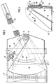
- den Düngerstreuer in der Ansicht von hinten,
- Fig.2
- den Düngerstreuer in Seitenansicht,
- Fig.3
- den Einstellmechanismus in der Ansicht von hinten im vergrößerten Maßstab,
- Fig.4
- den Einstellmechanismus in Seitenansicht in dem Maßstab gemäß Fig.3,
- Fig.5
- den Einstellmechanismus in vergrößertem Maßstab in Teilansicht,
- Fig.6
- den Einstellmechanismus in Seitenansicht in dem Maßstab gemäß Fig.5,
- Fig.7
- einen weiteren Düngerstreuer in Seitenansicht und
- Fig.8
- den Düngerstreuer gemäß Fig.7 in der Ansicht von hinten.
- Fig. 1
- the fertilizer spreader from behind,
- Fig. 2
- the fertilizer spreader in side view,
- Fig. 3
- the adjustment mechanism in the view from behind on an enlarged scale,
- Fig. 4
- the adjustment mechanism in side view on the scale of Figure 3,
- Fig. 5
- the adjustment mechanism on an enlarged scale in partial view,
- Fig. 6
- the adjustment mechanism in side view on the scale of Figure 5,
- Fig. 7
- another fertilizer spreader in side view and
- Fig. 8
- the fertilizer spreader according to Figure 7 in the view from behind.
Der Zentrifugaldüngerstreuer gemäß der Fig.1-6 weist den Vorratsbehälter 1 und
den Rahmen 2 auf. Am Rahmen 2 sind auf der Vorderseite die
Dreipunktkupplungselemente 3 angeordnet, über welche der
Zentrifugaldüngerstreuer an den Dreipunktkraftheber eines nicht dargestellten
Schleppers anzubauen ist. Der Vorratsbehälter 1 ist in seinem unteren Bereich
durch das dachförmige Mittelteil 4 in die beiden Auslauftrichter 5 aufgeteilt. Im
unteren Bereich der Seitenwände 6 des dachförmigen Mittelteiles 4 sind die
Auslauföffnungen 7 angeordnet. Vor den Auslauföffnungen 7 ist jeweils ein
Schieber 8 angeordnet, mittels welchen die Öffnungsweite der
jeweiligenAuslauföffnungen 7 einzustellen und die Auslauföffnungen zu
verschließen ist.The centrifugal fertilizer spreader according to Fig.1-6 has the reservoir 1 and
the
Unterhalb der Auslauföffnung 5 sind die Schleuderscheiben 9 mit ihren
Wurfelementen 10 und 11 auf den Getriebeausgangswellen 12 des Getriebes 13,
welches am Rahmen 2 befestigt ist, angeordnet. Über das Getriebe 13 werden die
Schleuderscheiben 9 im entgegengesetzten Drehsinn zueinander rotierend
angetrieben, und zwar in der Weise, daß sie im mittleren Bereich vorne aufeinander
zulaufen. Auf dem oberen Ende der Getriebeausgangswellen 12 ist oberhalb der
Schleuderscheiben 9 eine Rohrhülse 14 drehfest angeordnet. Die Rohrhülse 14 ist
mit der Getriebeausgangswelle 12 verbunden. Auf der Rohrhülse 14 ist das sich im
unteren Bereich des Vorratsbehälters 1 vor der Auslauföffnung 7 sich befindende
Rührorgan 15 angeordnet. Vor den Auslauföffnungen 7 befinden sich die Schieber 8
zur Einstellung der Öffnungsgröße der Auslauföffnung 7. Die Schieber 8 bilden
zusammen mit den Auslauföffnungen 7 die Dosierorgane 16.Below the
Den Schiebern 8 sind die als Hydraulikzylinder 17 ausgebildeten
Betätigungselemente zugeordnet. Mittels dieser Hydraulikzylinder 17 werden die
Schieber 8 in Schließstellung gebracht, so daß die Auflauföffnungen 7 verschlossen
sind. Desweiteren sind an den Schiebern 8 die Verbindungselemente 18 mittels als
Kugelköpfe 19 ausgebildeten Gelenke angeordnet. Diese Verbindungselemente 18
sind an einem Hebel 20 mittels das als Kugelkopf 21 ausgebildetem Gelenkes
angeordnet. Dieser Hebel 20 ist schwenkbar auf dem Bolzen 22 an dem
Halteelement 23 angeordnet. Das Halteelement 23 ist an der Rückwand 24 des
Vorratsbehälters 1 befestigt. An dem Halteelement 23 ist die Skala 25 angeordnet.
Hinter dem Halteelement 23 befindet sich das Gegenhalteelement 26 in einem
Abstand zu dem Halteelement 23. Zwischen dem Gegenhaltelement 26 und dem
Halteelement 24 wird der Hebel 20 geführt. Auf der Vorderseite des Halteelementes
23 ist auf dem Bolzen 22 der Zeiger 27 schwenkbar gelagert. Der an dem Zeiger 27
angeordnete Bolzen 28 durchsetzt ein in dem Haltelement 23 bogenförmig
angeordnetes Langloch 29. Auf der Rückseite des Halteelementes 23 ist auf dem
Bolzen 28 ist der Ansatz 30 angeordnet, der den Anschlag 31 für den Hebel 20
bildet. Anhand der Skala 25 läßt sich der Zeiger 27 und somit der Anschlag 31 für
den Einstellhebel 20 entsprechend der gewünschten Ausbringmenge einstellen. In
der in Fig.1 gezeigten Position befinden sich die Anschläge 31 in der Position fuhr die
größtmögliche Ausbringmenge. Die Schieber 8 sind ebenfalls in der größten
möglichen Öffnungstellung für die Auflauföffnungen 7 eingezeichnet. In den mit
strichpunktierten Linien dargestellten Positionen befinden sich die Hebel 20 in der
geschlossen Position für die Schieber 8. An dem Hebel 20 greift jeweils eine
Zugfeder 32 an, die an dem Vorratsbehälter 1 befestigt ist. Die Feder 32 ist an dem
Einstellhebel 20 derart angeordnet, daß die Verbindungselemente 18 immer auf
Zug belastet sind. Somit zieht also die Feder 32 die Schieber 8 in Richtung ihrer
Öffnungstellung für die Auslauföffnungen 7. Hierdurch wird erreicht, daß die
Schieber 8 immer in die gewünschten Öffnungsposition gebracht werden. Somit
wird also evtl. in dem Verbindungsgestänge 18 vorhandenes Spiel ausgeschaltet.The
Die Einstellhebel 20 sind um eine in Fahrtrichtung 33 verlaufende Achse 34, die
durch die Bolzen 22 verläuft angeordnet, schwenkbar am Streuer befestigt. Die
Anschläge 31 mit den Skalen 25 befinden sich im hinteren-oberen, nach oben
verlaufenden Bereich 35 des Vorratsbehälters 1. Die Einstellhebel 20 sind möglichst
dicht an der hinteren Vorratsbehälterwand 24 liegend angeordnet. Desweiteren sind
die Einstellhebel 20, Anschläge 31 und Skalen 25 zumindest 40-50 cm oberhalb der
Streuorgane 10 angeordnet. Somit befinden sich die Einstellhebel 20, Skalen 25
und Anschläge 31 außerhalb des Bereiches 36, in dem sich während des Betriebes
Düngerstaub ablagert. Die Skalen 25 reichen etwa bis an das obere Ende 37 des
trichterförmigen Bereiches des Vorratsbehälters 1. Die Anschläge 31 und Skalen 25
sind in einer aufrechten Ebene am Vorratsbehälter befestigt. Die Verbindungsstangen
18 können an der Vorratsbehälterwand 24 verlaufen, wie es in Fig.2
dargestellt wird. Falls gewünscht, können die Stangen 18 unmittelbar an die
Vorratsbehälterwand 24 mit einem kleinen Spalt anschließen.The adjusting levers 20 are about an
Der Düngerstreuer gemäß der Fig.7 und 8 weist den Vorratsbehälter 38 und den
Rahmen 39 auf. Am Rahmen 39 sind auf der Vorderseite die Dreipunktkupplungselemente
3 angeordnet, über welche der Zentrifugaldüngerstreuer an den
Dreipunktkraftheber eines nicht dargestellten Schleppers anzubauen ist. Der
Vorratsbehälter 38 ist in seinem unteren Bereich durch das dachförmige Mittelteil 40
in die beiden Auslauftrichter 41 aufgeteilt. Die beiden Auslauftrichter 41 werden
durch Bodenplatten 42 abgeschlossen, in denen sich jeweils eine Auflauföffnung
befindet. Unterhalb der Bodenplatte befindet sich jeweils ein Schieber 43, mittels
welchem die Öffnungsweite der Auflauföffnung einzustellen und zu verschließen ist.The fertilizer spreader according to Figures 7 and 8 has the
Unterhalb jeder Bodenplatte 42 bzw. jeder Auflauföffnung ist eine Schleuderscheibe
44 mit Wurfelementen 45 auf den Getriebeausgangswellen 46 des Getriebes
angeordnet. Über die Getriebe werden die Schleuderscheiben 44 im
entgegengesetzten Drehsinn rotierend zueinander angetrieben.There is a centrifugal disc underneath each
Den Schiebern 43 sind als Hydraulikzylinder ausgebildete Betätigungselemente, die
nicht dargestellt sind, zugeordnet. Mittels der Hydraulikzylinder werden die Schieber
43 in Schließstellung gebracht, so daß die Auslauföffnungen verschlossen sind.
Desweiteren sind an den Schiebern 43 Verlängerungshebel 47 befestigt. An den
Enden 48 der Verlängerungshebel 47 sind Verbindungselemente 49 mittels der als
Kugelköpfe 50 ausgebildeten Gelenken angeordnet. Die Verbindungselemente 49
sind weiterhin an ihrer anderen Seite an einem Einstellhebel 51 mittels eines als
Kugelkopf 51 ausgebildeten Gelenkes angeordnet. Dieser Einstellhebel 51 ist
schwenkbar auf dem Bolzen 53, der an dem Behälter 38 befestigt ist, angeordnet.
Dem äußeren Ende des Einstellhebel 51 ist eine Skala 54 und ein als Anschlag
wirkendes Einstellelement 55, welches an Hand der Skala 54 eingestellt werden
kann, zugeordnet. Der Anschlag 55 ist verstellbar und in exakt definierten
Positionen einstellbar. Zwischen dem äußeren Ende des Einstellhebels 51 und dem
Vorratsbehälter 38 ist eine Feder 56 derart angeordnet, daß die Feder 56 den
Schieber 43 in Richtung seiner Öffnungstellung zieht. Die Zugfeder 56 zieht den
Einstellhebel 51 gegen den Anschlag 55, somit wird der Schieber 43 immer in der
gewünschten Öffnungsposition gebracht. Die Feder 56 ist derart angeordnet, daß
sie den Schieber 43 aufzieht, somit wird evtl. in dem Übertragungsgestänge
vorhandenes Spiel ausgeschaltet.The
Der Einstellhebel 51 ist jeweils um eine in Fahrtrichtung 33 verlaufende Achse 34,
die durch den Bolzen 53 verläuft angeordnet und schwenkbar am Streuer befestigt.
Die Anschläge 55 mit den Skalen 54 befinden sich im hinteren oberen,
vorzugsweise schräg nach oben verlaufenden Bereich des Vorratsbehälters 38. Die
Einstellhebel 51 sind möglichst dicht an der hinteren Vorratsbehälterwand 57
liegend angeordnet. Die Einstellhebel 51, Anschläge 55 und Skalen 54 befinden
sich zumindest 40-50 cm oberhalb der Streuorgane 44. Somit befinden sich die
Skalen 54 und Anschläge 55 außerhalb des Bereiches, in dem sich während des
Betriebes Düngerstaub ablagert.The adjusting
Claims (10)
- Centrifugal fertilizer broadcaster provided with a hopper (1), at least two outlet apertures (7) being provided in the lower region of said hopper, which apertures are adjustable and closable in respect of their width of opening by sliders (8), driven scattering elements being disposed beneath the outlet apertures (7), the widths of opening of the outlet apertures (7) being determinable by adjusting levers (20,21 51), which co-operate with sliders and are disposed on the rear side of the broadcaster, and by stop members (31,55) which co-operate with scales (25,54) on the rear side of the broadcaster, the stop members (31,55) and the sliders (8) and/or the adjusting levers (20,21 51) being adjustable independently of one another, characterised in that the adjusting levers (20,21 51) are each disposed on the broadcaster so as to be pivotable about an axis (34), which extends at least approximately in the direction of travel (33), in that the stop members (31,55), together with the scales (25,54), are disposed at least in the rear-upper, upwardly extending region of the hopper (1,38), and in that the adjusting levers (20,51) are situated so as to lie as close as possible to the rear hopper wall (24).
- Centrifugal fertilizer broadcaster according to claim 1, characterised in that connection members are disposed between the sliders (8,43) and/or the transmission levers (18,49), on the one hand, and the adjusting levers (20,51), on the other hand, by means of pivot joints.
- Centrifugal fertilizer broadcaster according to one or more of the preceding claims, characterised in that the pivot] joints are configured as spherical ends (21,50,52).
- Centrifugal fertilizer broadcaster according to one or more of the preceding claims, characterised in that the connection members are configured as resiliently sprung struts.
- Centrifugal fertilizer broadcaster according to one or more of the preceding claims, characterised in that springs (32,56) are disposed between the hopper (1,38) and/or frame (2,39) and the adjusting levers (20,51) in such a manner that the connection members are always tensilely loaded.
- Centrifugal fertilizer broadcaster according to one or more of the preceding claims, characterised in that the adjusting levers (20,51), stop members (31,55) and scales (24 25,54) are situated at least 40-50 cm above the scattering elements.
- Centrifugal fertilizer broadcaster according to one or more of the preceding claims, characterised in that the adjusting levers (20,51), scales (24 25,54) and stop members (31,55) are disposed externally of the region in which powdered fertilizer is deposited during the operation.
- Centrifugal fertilizer broadcaster according to one or more of the preceding claims, characterised in that the scales (24 25,54) extend at least approximately to the upper end of the funnel-shaped region of the hopper (1,38).
- Centrifugal fertilizer broadcaster according to one or more of the preceding claims, characterised in that the scales (24 25,54) and stop members (31,55) are disposed in an upwardly extending plane.
- Centrifugal fertilizer broadcaster according to one or more of the preceding claims, characterised in that the scales (24 25,54) and stop members (31,55) are disposed so as to extend slightly inclinedly upwardly and rearwardly.
Applications Claiming Priority (3)
| Application Number | Priority Date | Filing Date | Title |
|---|---|---|---|
| DE19504983A DE19504983A1 (en) | 1995-02-15 | 1995-02-15 | Centrifugal fertilizer spreader |
| DE19504983 | 1995-02-15 | ||
| PCT/EP1996/000125 WO1996025027A1 (en) | 1995-02-15 | 1996-01-12 | Centrifugal fertiliser spreader |
Publications (2)
| Publication Number | Publication Date |
|---|---|
| EP0809427A1 EP0809427A1 (en) | 1997-12-03 |
| EP0809427B1 true EP0809427B1 (en) | 1998-10-07 |
Family
ID=7753981
Family Applications (1)
| Application Number | Title | Priority Date | Filing Date |
|---|---|---|---|
| EP96900319A Expired - Lifetime EP0809427B1 (en) | 1995-02-15 | 1996-01-12 | Centrifugal fertiliser spreader |
Country Status (7)
| Country | Link |
|---|---|
| EP (1) | EP0809427B1 (en) |
| DE (2) | DE19504983A1 (en) |
| DK (1) | DK0809427T3 (en) |
| ES (1) | ES2123332T3 (en) |
| PL (1) | PL181829B1 (en) |
| SK (1) | SK28897A3 (en) |
| WO (1) | WO1996025027A1 (en) |
Families Citing this family (2)
| Publication number | Priority date | Publication date | Assignee | Title |
|---|---|---|---|---|
| DE202019003491U1 (en) * | 2019-08-23 | 2020-08-26 | Rauch Landmaschinenfabrik Gmbh | Double disc spreader |
| CN113728793B (en) * | 2021-09-07 | 2022-06-17 | 农业农村部南京农业机械化研究所 | Grain combined harvesting and fertilizer spreading all-in-one machine for interplanting mode |
Family Cites Families (2)
| Publication number | Priority date | Publication date | Assignee | Title |
|---|---|---|---|---|
| US2526081A (en) * | 1947-07-16 | 1950-10-17 | Henry H Meincke | Fertilizer distributor |
| DE3920778A1 (en) * | 1989-06-24 | 1991-01-03 | Amazonen Werke Dreyer H | CENTRIFUGAL FERTILIZER SPREADER |
-
1995
- 1995-02-15 DE DE19504983A patent/DE19504983A1/en not_active Withdrawn
-
1996
- 1996-01-12 DK DK96900319T patent/DK0809427T3/en active
- 1996-01-12 DE DE59600647T patent/DE59600647D1/en not_active Expired - Lifetime
- 1996-01-12 SK SK288-97A patent/SK28897A3/en unknown
- 1996-01-12 PL PL96319818A patent/PL181829B1/en not_active IP Right Cessation
- 1996-01-12 EP EP96900319A patent/EP0809427B1/en not_active Expired - Lifetime
- 1996-01-12 WO PCT/EP1996/000125 patent/WO1996025027A1/en active IP Right Grant
- 1996-01-12 ES ES96900319T patent/ES2123332T3/en not_active Expired - Lifetime
Also Published As
| Publication number | Publication date |
|---|---|
| DE19504983A1 (en) | 1996-08-22 |
| PL181829B1 (en) | 2001-09-28 |
| DE59600647D1 (en) | 1998-11-12 |
| WO1996025027A1 (en) | 1996-08-22 |
| SK28897A3 (en) | 1998-06-03 |
| ES2123332T3 (en) | 1999-01-01 |
| EP0809427A1 (en) | 1997-12-03 |
| DK0809427T3 (en) | 1999-06-21 |
| PL319818A1 (en) | 1997-09-01 |
Similar Documents
| Publication | Publication Date | Title |
|---|---|---|
| EP0084872B1 (en) | Manure spreader | |
| DE2943721A1 (en) | SPREADER FOR GRAINY OR POWDERED SPREADING GOODS | |
| EP0820219B1 (en) | Centrifugal fertiliser spreader | |
| EP0545894B2 (en) | Broadcaster | |
| DE102005015228B4 (en) | Centrifugal spreader for spreading material | |
| DE3924334A1 (en) | SINGLE SPREADER FOR GIANT CAPABILITY, IN PARTICULAR DUENGER | |
| EP0968639B1 (en) | Centrifugal fertiliser spreader | |
| EP0809427B1 (en) | Centrifugal fertiliser spreader | |
| EP1031268B1 (en) | Centrifugal fertiliser spreader | |
| EP0405180B2 (en) | Broadcaster | |
| DE2010863A1 (en) | Spreader | |
| DE3405245A1 (en) | SPREADER FOR GRAINY AND / OR POWDERED SPREADING GOODS | |
| EP0356770B1 (en) | Spinning fertilizer distributors | |
| EP0613613A1 (en) | Broadcaster | |
| DE4302802A1 (en) | Agricultural dung spreading machine with spinning discs | |
| DD297905A5 (en) | SCHLEUDERDUENGERSTREUER | |
| EP0386540B1 (en) | System for making a series broadcaster | |
| DE1945077B2 (en) | Spreader for granular or powdery grit | |
| DE4036235A1 (en) | SLINGER SPREADER | |
| DE4102986A1 (en) | SLINGER SPREADER | |
| DE4102092A1 (en) | Centrifugal fertiliser distributor machine - with two functional options on one base design | |
| DE19606586A1 (en) | Centrifugal fertilizer spreader | |
| DE10033674A1 (en) | Centrifugal manure spreader has revolution rate adjustment devices arranged in centrifugal plate drive and centrifugal plates can be rotated at different speeds | |
| AT267930B (en) | Spreader | |
| EP0410109A1 (en) | Centrifugal spreader for pourable material, especially fertilizer |
Legal Events
| Date | Code | Title | Description |
|---|---|---|---|
| PUAI | Public reference made under article 153(3) epc to a published international application that has entered the european phase |
Free format text: ORIGINAL CODE: 0009012 |
|
| 17P | Request for examination filed |
Effective date: 19970729 |
|
| AK | Designated contracting states |
Kind code of ref document: A1 Designated state(s): DE DK ES FR GB NL |
|
| GRAG | Despatch of communication of intention to grant |
Free format text: ORIGINAL CODE: EPIDOS AGRA |
|
| 17Q | First examination report despatched |
Effective date: 19971217 |
|
| GRAG | Despatch of communication of intention to grant |
Free format text: ORIGINAL CODE: EPIDOS AGRA |
|
| GRAH | Despatch of communication of intention to grant a patent |
Free format text: ORIGINAL CODE: EPIDOS IGRA |
|
| GRAH | Despatch of communication of intention to grant a patent |
Free format text: ORIGINAL CODE: EPIDOS IGRA |
|
| GRAA | (expected) grant |
Free format text: ORIGINAL CODE: 0009210 |
|
| AK | Designated contracting states |
Kind code of ref document: B1 Designated state(s): DE DK ES FR GB NL |
|
| REF | Corresponds to: |
Ref document number: 59600647 Country of ref document: DE Date of ref document: 19981112 |
|
| ET | Fr: translation filed | ||
| REG | Reference to a national code |
Ref country code: ES Ref legal event code: FG2A Ref document number: 2123332 Country of ref document: ES Kind code of ref document: T3 |
|
| GBT | Gb: translation of ep patent filed (gb section 77(6)(a)/1977) |
Effective date: 19990104 |
|
| REG | Reference to a national code |
Ref country code: DK Ref legal event code: T3 |
|
| PLBE | No opposition filed within time limit |
Free format text: ORIGINAL CODE: 0009261 |
|
| STAA | Information on the status of an ep patent application or granted ep patent |
Free format text: STATUS: NO OPPOSITION FILED WITHIN TIME LIMIT |
|
| 26N | No opposition filed | ||
| REG | Reference to a national code |
Ref country code: GB Ref legal event code: IF02 |
|
| PGFP | Annual fee paid to national office [announced via postgrant information from national office to epo] |
Ref country code: GB Payment date: 20021224 Year of fee payment: 8 |
|
| PG25 | Lapsed in a contracting state [announced via postgrant information from national office to epo] |
Ref country code: GB Free format text: LAPSE BECAUSE OF NON-PAYMENT OF DUE FEES Effective date: 20040112 |
|
| GBPC | Gb: european patent ceased through non-payment of renewal fee |
Effective date: 20040112 |
|
| PGFP | Annual fee paid to national office [announced via postgrant information from national office to epo] |
Ref country code: NL Payment date: 20060124 Year of fee payment: 11 |
|
| PGFP | Annual fee paid to national office [announced via postgrant information from national office to epo] |
Ref country code: ES Payment date: 20070115 Year of fee payment: 12 |
|
| NLV4 | Nl: lapsed or anulled due to non-payment of the annual fee |
Effective date: 20070801 |
|
| PG25 | Lapsed in a contracting state [announced via postgrant information from national office to epo] |
Ref country code: NL Free format text: LAPSE BECAUSE OF NON-PAYMENT OF DUE FEES Effective date: 20070801 |
|
| REG | Reference to a national code |
Ref country code: ES Ref legal event code: FD2A Effective date: 20080114 |
|
| PGFP | Annual fee paid to national office [announced via postgrant information from national office to epo] |
Ref country code: DK Payment date: 20090122 Year of fee payment: 14 |
|
| PG25 | Lapsed in a contracting state [announced via postgrant information from national office to epo] |
Ref country code: ES Free format text: LAPSE BECAUSE OF NON-PAYMENT OF DUE FEES Effective date: 20080114 |
|
| REG | Reference to a national code |
Ref country code: DK Ref legal event code: EBP |
|
| PG25 | Lapsed in a contracting state [announced via postgrant information from national office to epo] |
Ref country code: DK Free format text: LAPSE BECAUSE OF NON-PAYMENT OF DUE FEES Effective date: 20100131 |
|
| PGFP | Annual fee paid to national office [announced via postgrant information from national office to epo] |
Ref country code: FR Payment date: 20120202 Year of fee payment: 17 |
|
| REG | Reference to a national code |
Ref country code: FR Ref legal event code: ST Effective date: 20130930 |
|
| PG25 | Lapsed in a contracting state [announced via postgrant information from national office to epo] |
Ref country code: FR Free format text: LAPSE BECAUSE OF NON-PAYMENT OF DUE FEES Effective date: 20130131 |
|
| PGFP | Annual fee paid to national office [announced via postgrant information from national office to epo] |
Ref country code: DE Payment date: 20140108 Year of fee payment: 19 |
|
| REG | Reference to a national code |
Ref country code: DE Ref legal event code: R119 Ref document number: 59600647 Country of ref document: DE |
|
| PG25 | Lapsed in a contracting state [announced via postgrant information from national office to epo] |
Ref country code: DE Free format text: LAPSE BECAUSE OF NON-PAYMENT OF DUE FEES Effective date: 20150801 |