EP0809318B1 - Circulateur - Google Patents
Circulateur Download PDFInfo
- Publication number
- EP0809318B1 EP0809318B1 EP97850064A EP97850064A EP0809318B1 EP 0809318 B1 EP0809318 B1 EP 0809318B1 EP 97850064 A EP97850064 A EP 97850064A EP 97850064 A EP97850064 A EP 97850064A EP 0809318 B1 EP0809318 B1 EP 0809318B1
- Authority
- EP
- European Patent Office
- Prior art keywords
- waveguide
- hole
- circulator according
- circulator
- wall
- Prior art date
- Legal status (The legal status is an assumption and is not a legal conclusion. Google has not performed a legal analysis and makes no representation as to the accuracy of the status listed.)
- Expired - Lifetime
Links
- 229910000859 α-Fe Inorganic materials 0.000 claims description 43
- 239000000126 substance Substances 0.000 claims description 20
- 230000004907 flux Effects 0.000 claims description 2
- 238000010276 construction Methods 0.000 description 5
- 238000003780 insertion Methods 0.000 description 4
- 230000037431 insertion Effects 0.000 description 4
- 238000002955 isolation Methods 0.000 description 4
- 238000004519 manufacturing process Methods 0.000 description 4
- 238000012986 modification Methods 0.000 description 4
- 230000004048 modification Effects 0.000 description 4
- 239000000463 material Substances 0.000 description 3
- 239000002184 metal Substances 0.000 description 3
- 230000008901 benefit Effects 0.000 description 2
- 239000003989 dielectric material Substances 0.000 description 2
- 239000003292 glue Substances 0.000 description 2
- 239000012858 resilient material Substances 0.000 description 2
- 238000004026 adhesive bonding Methods 0.000 description 1
- 238000004220 aggregation Methods 0.000 description 1
- 230000002776 aggregation Effects 0.000 description 1
- 230000002238 attenuated effect Effects 0.000 description 1
- 230000009286 beneficial effect Effects 0.000 description 1
- 230000005540 biological transmission Effects 0.000 description 1
- 239000000919 ceramic Substances 0.000 description 1
- 230000008859 change Effects 0.000 description 1
- 238000004891 communication Methods 0.000 description 1
- 239000004020 conductor Substances 0.000 description 1
- 238000009826 distribution Methods 0.000 description 1
- 230000000694 effects Effects 0.000 description 1
- 230000002349 favourable effect Effects 0.000 description 1
- 230000001771 impaired effect Effects 0.000 description 1
- 230000010363 phase shift Effects 0.000 description 1
- 238000012545 processing Methods 0.000 description 1
Images
Classifications
-
- H—ELECTRICITY
- H01—ELECTRIC ELEMENTS
- H01P—WAVEGUIDES; RESONATORS, LINES, OR OTHER DEVICES OF THE WAVEGUIDE TYPE
- H01P1/00—Auxiliary devices
- H01P1/32—Non-reciprocal transmission devices
- H01P1/38—Circulators
- H01P1/383—Junction circulators, e.g. Y-circulators
- H01P1/39—Hollow waveguide circulators
Definitions
- the present invention relates to the field of components intended for use in waveguide systems for frequencies in the microwave range and higher frequency ranges where the phase shifting ability of a ferrite substance placed in a magnetic field is utilized.
- microwaves here and in the following is meant signals with frequencies within the microwave range as well as signals with higher frequencies, for example within the millimetre wave range.
- the circulator is a component used in these situations, which has the property that it transmits microwave signals between certain of the waveguide ports (connections) comprised in the circulator, while other routes are blocked.
- a signal fed to port 1 is thus transmitted to port 2
- a signal fed to port 2 is transmitted to port 3
- a signal fed to port 3 is transmitted to port I, while the signals in the opposite direction are strongly attenuated, whereby an isolation between the ports is achieved.
- the property of a ferrite substance to phase shift microwave signals passing the ferrite, under the influence of a magnetic field is utilized.
- a circulator for which the mounting work has been somewhat simplified is described.
- a package comprising a ferrite substance in the shape of a puck has here been mounted on a fixing part which has then been introduced into the waveguide through a hole in one of the waveguide walls.
- the fixing part presses the packet towards the opposite waveguide wall so that the package is in this way kept in place in the waveguide.
- a flange at the fixing part lies in contact with an edge positioned in the hole to which it is also fixed with a screw.
- a package comprising ferrite substance in the shape of pucks is placed on a piston - which corresponds to the fixing part of the above mentioned abstract - which has then been guided into a waveguide through a hole in a waveguide wall.
- the piston is movable in the hole in the waveguide wall, with the appropriate clearance fit, and a spring element presses the piston towards the package with the ferrite pucks so that this package is held in place in the waveguide, between the piston and the opposite waveguide wall.
- the spring coefficient and the initial tension of the spring element have been chosen in such a way that the spring element can compensate for changes in the dimension caused by temperature variations without too high tension or play arising.
- This circulator however also has disadvantages.
- the piston and the body of the waveguide house can sometimes lack a good galvanic contact with each other. This causes the electrical properties of the circulator to be somewhat impaired - first and foremost regarding insertion loss.
- the present invention is intended to solve the following problem: Firstly to provide a circulator for which the mounting is simple and insensitive and for which the requirements on the dimensions of the comprised parts are reasonable. Secondly the performance of the circulator regarding galvanic contact between the parts, frequency properties, insertion loss, reflection and isolation must be good. Thirdly the circulator must be able to take vibrations, blows and large variations in temperature without being damaged and without the performance being significantly reduced.
- a package comprising a ferrite substance in the shape of a puck is arranged at a movable and electrically conductive element.
- a portion of the movable element is found in a hole in one of the waveguide walls of the circulator and is slideable in this hole.
- the package with the ferrite material is kept in place in a waveguide between the movable element and a waveguide wall, the waveguide wall being opposite to the waveguide wall at which the hole is located.
- one or more sections have been made deformable in the direction towards the wall of the hole.
- One or more press elements have been designed to press limited ranges of the deformable sections towards the wall of the hole.
- the distance between these limited ranges and the waveguide wall in which the hole is positioned is substantially equal to half the working wavelength of the circulator, whereby the circulator obtains particularly good electrical properties.
- the object of the invention is thus that when the limited ranges are pressed towards the wall of the hole a good mechanical and galvanic contact will arise between the movable element and the wall of the hole.
- the movable element is made up of a tubular metal piston.
- the shape of the piston corresponds to the shape of a hole in a waveguide wall, and the piston is, in whole or in part, arranged in this hole.
- the piston comprises a first end which as a suggestion is closed, so that a package of ferrite substance in the shape of a puck can be placed at this end.
- the package is kept in place in the waveguide between the first end of the piston and an opposite waveguide wall.
- the other end of the piston is open and provided with slits which as a suggestion extend substantially in the longitudinal direction of the piston.
- the edge of the tube at the open end of the piston can be deformed in relation to the rest of the piston in the direction towards the wall of the hole.
- the tube edge can however not be deformed in relation to the rest of the piston in the longitudinal direction of the hole.
- a press element lies close to the tube edge at the other end of the piston. It is suggested to place the surface of the press element that is close to the tube edge at such an angle that the press element exerts a force on the tube edge both in the longitudinal direction of the hole and in the direction towards the walls of the hole, whereby the piston is pressed in the direction towards the package with the ferrite substance wile the tube edge is pressed towards the wall of the hole.
- the press element can, for a piston with a circular cross-section, as a suggestion be a screw with a conical top, which conical top is intended to lie in contact with the tube edge.
- the hole in the waveguide wall is, for example, equipped with threads corresponding to the threads of the screw so that the screw can be inserted in the direction towards the tubular piston.
- the screw will here be screwed with a well defined momentum so that the package is brought into good contact with the opposite waveguide wall without at the same time exposing the ferrite substance to too high compressive stress.
- the invention has, in addition to solving the above listed problems, the advantage that the mounting becomes relatively simple and cheap.
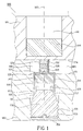
- Figure 1 is a cross-section of a first circulator construction in accordance with the invention.
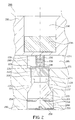
- Figure 2 is a cross-section of a second circulator construction in accordance with the invention.
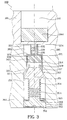
- Figure 3 is a cross-section of a third circulator construction in accordance with the invention.
- the circulator 100 in the example is a 3 port circulator.
- the ports on such a circulator are located at regular intervals around the circumference of the circulator, 120° apart.
- the cross section shown in the figure runs through the central point of one of the ports and the centre of the circulator.
- the circulator comprises a waveguide house, and in the embodiment shown in figure I comprises the waveguide house comprises two blocks, an upper part 101 and a lower part 102. These parts 101 and 102 are joined together in a suitable manner, for example with glue or with a screw union.
- the waveguide house is manufactured in an electrically conductive material, for example a metal. From the central axis 103 of the circulator three grooves with rectangular cross sections extend in the lower part.
- the three grooves are 120° apart. Together with the lower side of the upper part 101 the three grooves constitute waveguides which make up the ports of the circulator.
- the reference number 105 denotes such a port. This space may be given different shapes depending on the manufacturing method and the desired properties of the circulator 100.
- a hole 111 in which a movable element 114 may be moved with the appropriate clearance fit.
- the movable element 114 is shown in figure 1 as a tubular metal piston 114.
- the hole 111 and the piston 114 in the example shown here have circular cross sections.
- the end 117 of the piston facing away from the space 108 is open and provided with slits 120, which in the figure extent parallel to the central axis of the piston.
- the slits 120 divide the open end 117 of the piston 114 into a number of beam shaped sections. By selecting the dimension, positioning and number of the slits 120 in a suitable way, these sections have been made to be deformable in the direction towards the wall of the hole 111.
- the end 123 of the piston 114 which is close to the space 108 is closed and enters the space 108 by a certain distance.
- This end 123 of the piston therefore serves as a radial transformer, which transformer, with suitable height and diameter adjusts the circulator impedance to the impedances of the waveguides connected to the waveguide ports.
- This elevated portion determines, with a high degree of accuracy, the position of a casing 129 with thin walls, by making the inner diameter of the casing correspond to the diameter of the elevated portion.
- the casing 129 is manufactured in a dielectric material which is also relatively resilient.
- the length of the casing 129 is to correspond to the added height of the elevated portion 126, the ferrite pucks 132 and 135 and the dielectric puck 138.
- a magnet 144 which, together with a magnet 147 placed inside the tubular piston 114, creates a magnetic flux through the ferrite pucks 132 and 135.
- the hole 111 in the lower part 102 is a through hole and has an exit 150 on the lower side of the lower part.
- the hole 111 is provided at the exit 150 with threads which extend a bit into the hole.
- a press element in the shape of a screw 156 with corresponding threads 159 is screwed into the hole 111.
- the screw 156 has a conical top 162 which lies in contact with the edge 165 of the open end 117 of the tubular piston. To improve the contact, the edge 156 has a bevelling with a shape corresponding to the shape of the conical top 162.
- the conical top 162 presses the piston 114 in the direction of the hole 111, and the piston therefore in turn presses the upper ferrite puck 132 towards the upper part 101, whereby good mechanical contact, and thus also good thermal and galvanic contact, is achieved between the upper part, the pucks and the piston.
- the upper end of the casing 129 would extend past the ferrite puck 132 which is closest to the upper part 101, the casing will, because it has been manufactured in a relatively resilient material, be somewhat deformed, so that even in the most disadvantageous case the ferrite puck 132 will be in contact with the upper part 101. In the opposite situation, the end of the casing 129 will not reach the upper part 101, but this will in practice not affect the function.
- the slits 120 divide, as previously stated, the open end 117 of the piston 114 into a number of beam shaped sections, which are deformable in the direction towards the wall of the hole 111.
- the edge 165 of the open end 117 here constitutes a limited area of these deformable sections. When the conical top 162 presses against the edge 165, this edge will be pressed out against the walls of the hole 111, whereby a very good mechanical and galvanic contact is achieved between the edge 165 and the material in the wall of the hole.
- the good galvanic contact between the piston 114 and the material in the wall of the hole gives the circulator 100 improved electrical characteristics, primarily regarding insertion loss, but also regarding reflection and isolation.
- the good mechanical contact makes sure the piston 114 is centred well in the hole 111, so that the circulator 100 becomes easier to mount and can take blows and vibrations to a larger extent without its electrical performance being affected too much.
- microwave signals can propagate in the gap 168 between the piston 114 and the walls of the hole 111.
- the edge 165 of the open end 117 lies tight against the wall of the hole 111, so that this area of the piston can be seen as a short circuit.
- the microwave signals are reflected in this short circuit and this may result in resonance effects which might impair the performance of the circulator 100.
- the microwaves will then first propagate a distance of half a wavelength, then will be reflected and go back a distance half a wavelength, that is, in total one whole wavelength. This may be seen as the short circuit at the end of the piston where the slits are, is transformed up to the waveguide wall. In the microwave range, this corresponds to the situation where the gap 168 does not exist. Of course it works just as well if the distance between the wavelength wall 171 and the edge 165 substantially corresponds to an arbitrary integer number of half wavelengths (N* ⁇ /2).
- the dimensions of all components comprised in the circulator will change according to the coefficient of linear expansion of each substance. Temperature variations might therefore create so high compressive stress on the ferrite pucks 132 and 135 that they might be damaged. Of course also the opposite can occur, that is the compressive stress drops so that the contact between the upper ferrite puck 132 and the upper part 101 is not good enough. To make sure that none of this happens, it is suggested according to the invention to manufacture the dielectric puck 138 in a dielectric material which is also relatively resilient. This puck 138 can then be deformed and thereby compensate for the changes in dimensions of the other components, without the compressive state of the ferrite pucks 132 and 135 being affected.
- the magnet 147 is glued in place in the tubular piston 114.
- the casing 129 is pressed on to the elevated portion 126, which keeps the casing in place.
- the pucks 132, 135 and 138 are placed in the casing 129, where they are kept in place by the magnet.
- the open end 117 of the piston 114 which has the slits, is then placed on the conical top 162 of the screw 156, and the assembly is introduced so far into the hole 111 that the screw can be screwed in.
- the screw 156 is screwed until the casing 129 and the upper ferrite puck 132 touch the waveguide wall 174 in the upper part 101. Screwing in the screw then continues until a well defined torque is achieved, which torque has been chosen so that a suitable pressure is achieved between the upper part 101 and the ferrite puck 132 which touches this part.
- FIG 2 another embodiment of a circulator 200 according to the invention is shown.
- the circulator 200 in figure 2 shows major similarities with the one in figure 1 and therefore primarily the differences are described.
- the parts that are the same in the two embodiments is only described very briefly or omitted from the description.
- a piston 214 drawn in figure 2 in the same way as the piston in figure 1, is arranged in a hole 211 corresponding to the hole 111 in figure 1.
- a casing 229, two ferrite pucks 232 and 235 and a dielectric puck 238 are held in place in a space 208 between the piston 214 and an upper part 201.
- the hole 211 has, just like the hole 111 in figure 1, an exit on the lower side of a lower part 202 and threads 253 extend from this exit 250 into the hole 211.
- the screw 156 in figure 1 has been replaced with two parts, a contact element 255 and a twist-on cap 260.
- the contact element 255 is arranged in the hole 211 with the appropriate clearance fit and has conical upper side 257 and a plane under side 258.
- the conical upper side 257 lies in contact with the edge 265 of the open end 217.
- the twist-on cap 260 is provided with threads 261 corresponding to the threads 253 in the hole 211 and is also screwed into these threads.
- the side of the twist-on cap 260 facing the contact element 255 is provided with a convex part 263 and this convex part lies in contact with the plane underside 258 of the contact element 255.
- the convex part 263 of the twist-on cap 260 is made so that the twist-on cap and the contact element 255 can easily be turned relative to each other without any significant torque arising between these parts.
- the twist-on cap 260 thus presses the contact element 255 in the longitudinal direction of the hole 211 and the contact element in turn presses against the edge 265 of the end of the piston 214 where the slits are.
- the parts comprised in the circulator 200 are, just as in the circulator 100 in figure 1, dimensioned in such a way that the distance between the waveguide wall 271 in the lower part 202 and the edge 256 of the open end 217 substantially corresponds to half the wavelength ( ⁇ /2) of the working wavelength of the circulator 200.
- the dielectric puck 238 may, just as in the circulator 100 of figure 1, be manufactured in a relatively resilient material.
- the mounting of the embodiment in figure 2 becomes precise and easy to perform.
- the casing 229, the magnet 247 and the pucks 232, 235 and 238 are mounted at the piston 214 in a corresponding way as with the circulator 100 of figure 1.
- the open end 217 of the piston 214 is placed on the conical upper side 247 of the contact element 255.
- the piston 214, the casing 229, the pucks 232, 235 and 238 and the contact element 225 are then introduced into the hole 211 through the exit 250.
- the convex part 263 of the twist-on cap 260 is brought in contact with the underside 258 of the contact element 255, and the twist-on cap is twisted into the hole 211 until the casing 229 and the upper ferrite puck 232 touch the waveguide wall 274 in the upper part 201.
- the twisting on of the twist-on cap 260 then continues until a well-defined torque is achieved, which torque has been selected so that the pressure between the upper part 201 and the ferrite puck 232 touching this part obtains a reasonable value.
- the piston 214 and the hole 211 have circular shapes in the circulator 200 shown in figure 2. With a couple of minor modifications the circulator construction of figure 2 will however allow other shapes of the piston and the hole - which the circulator of figure 1 does not allow.
- the piston may be given a rectangular cross-section and the modifications needed for this are the following.
- the portion of the hole in which the rectangular piston is to be arranged with the appropriate clearance fit must of course have a corresponding rectangular shape.
- the rest of the hole does not need to have a rectangular shape, but must be dimensioned so that there is no risk that the piston will get stuck when the circulator is being mounted.
- the threaded portion of the hole must however still have a circular shape, so that the twist-on cap may be put on.
- the far end of the piston from the space is still open and has slits. It is however an advantage if the slits have been placed in the corners of the rectangle, as the edge of the open end in this case will be more easily deformed against the wall of the hole.
- the upper side of the contact element cannot be conical but instead may advantageously have a pyramid shape so that the upper side of the contact element can lie close to the edge of the open end, which is now rectangular.
- the shape of the contact element must in all other aspects be such that the contact element is arranged in the hole with the appropriate clearance fit.
- FIG 3 yet another embodiment of a circulator 300 according to the invention is shown.
- This circulator 300 also has major similarities with the circulator 100 of figure 1, and therefore primarily the differences will be described, whereas the similarities will be described briefly or omitted from the description.
- a casing 329 Just like in figure 1 a casing 329, two ferrite pucks 333 and 335 and a dielectric puck 338 are held in place in a space 308 between the piston 314 and an upper part 301.
- the hole 311 has, just like the hole 111 in figure 1, an exit 350 on the underside of a lower part 302, and threads 353 extend from this exit 350 into the hole 311.
- the screw 156 of the circulator 100 in figure 1 has in the circulator 300 of figure 3 been replaced with three parts: a contact element 355, a twist-on cap 360 and a coil spring 364.
- the contact element 355 has a conical upper side 357 which lies in contact with the edge 365 of the open end 317 of the piston 314.
- the underside 358 of the contact element 355 is provided with a protruding part 354 with a circular cylindrical shape. This protruding part 354 is positioned so that its centre line coincides with the centre line of the conical upper side 357.
- the twist-on cap 360 is provided with threads 316 corresponding to the threads 353 in the hole 311 and is screwed into the hole.
- the side of the twist-on cap 360 which faces the contact element 355 is provided with a protruding part 363 with a circular cylindrical shape. This protruding part 363 has the same diameter as the protruding part 354 of the underside 358 of the contact element 355.
- the coil spring 364 has an inner diameter corresponding to the diameters of the two protruding part 354 and 363 and with one end lies in contact with the underside 358 of the contact element 355 and with its other end to the side of the twist-on cap 360 facing the contact element 355.
- the coil spring here encloses the two protruding parts 354 and 363, whereby the coil spring 364 is prevented from moving perpendicularly to the longitudinal direction of the hole 311.
- the coil spring 364 is partially compressed and thus exerts a force between the twist-on cap 360 and the contact element 355.
- the contact element 355 is therefore pressed against the edge 365 of the open end 317 of the piston 314.
- the parts comprised in the circulator 300 are, just as in the circulator 100 of Figure 1, dimensioned in such a way that the distance between the waveguide wall 371 in the lower part 302 and the edge 365 of the open end 317 substantially corresponds to half the wavelength of the wavelength intended for the circulator.
- the coil spring can be deformed and thus compensate for size changes brought on by temperature variations, in the components comprised in the circulator 300, without significantly affecting the compressive states of the pucks 332, 335 and 338.
- the circulator 300 can therefore take large variations in temperature without any risk that the ferrite pucks 332 and 335 will be damaged or that the performance of the circulator 300 is deteriorated in other aspects.
- the dielectric puck 338 can be of a ceramic substance.
- the mounting of the embodiment of figure 3 becomes precise and simple to perform.
- the casing 329, the magnet 347 and the pucks 332, 335 and 338 are assembled with the piston 314 in a corresponding way as for the circulator 100 of figure 1.
- the open end 317 of the piston, which has the slits, is placed on the conical upper side 357 of the contact element 355.
- One end of the coil spring 364 is placed around the protruding part 354 on the lower side 358 of the contact element 314.
- the contact element 314 and the coil spring are introduced through the exit 350 so far into the hole that the casing 329 and the pucks 332, 335 and 338 get in contact with the upper part 301.
- the other end of the coil spring is placed around the protruding part 363 of the twist-on cap 360, and the twist-on cap is introduced in the exit 350 so that it can be twisted on.
- the twist-on cap 360 is twisted a predetermined number of turns. The number of turns has been selected with respect to the sizes of the circulator components and the spring coefficient of the coil spring 364, so that the pressure between the upper part 301 and the ferrite puck 332 lying in contact with the upper part 301 obtains a suitable value.
- the circulator 300 of Figure 3 can, if it is modified, also be used if the piston and the hole are not circular.
- the ferrite and dielectric pucks which have been given a circular shape in the embodiments described above, can of course have another shape, for example triangular. Depending on the desired electrical properties the distribution and the placement of the pucks may be varied. In some applications for example dielectric pucks may be completely left out.
- the shape of the dielectric casing must be adapted to these modifications, but as the task of the casing is primarily to keep the pucks together it can in some applications be left out or replaced with, as an example, glue.
- the coil spring 364 of Figure 3 can of course be replaced with another spring, for example a spring clip.
Landscapes
- Non-Reversible Transmitting Devices (AREA)
Claims (22)
- Circulateur pour des fréquences dans la gamme des hyperfréquences et des fréquences plus élevées, comportant un logement à guide d'onde en une substance électriquement conductrice ; une première paroi (171 ; 271 ; 371) de guide d'onde agencée dans le logement à guide d'onde ; un trou (111 ; 211 ; 311) agencé dans la première paroi de guide d'onde et s'étendant vers l'intérieur du logement à guide d'onde ; une seconde paroi de guide d'onde (174 ; 274 ; 374) agencée dans le logement à guide d'onde et opposée à la première paroi de guide d'onde ; un nombre prédéterminé de parois additionnelles de guide d'onde, agencées d'une manière telle qu'elles forment ensemble, avec les première et seconde parois de guide d'onde, un système de guide d'onde, situé dans le logement à guide d'onde, lequel système de guide d'onde présente au moins trois orifices (105 ; 205 ; 305) de guide d'onde ; un élément mobile (114 ; 214 ; 314) en substance électriquement conductrice et comprenant à son tour une partie qui est agencée de façon coulissante dans le trou ; au moins un galet de ferrite (132 ; 135 ; 232, 235 ; 332, 335) agencé entre l'élément mobile et la seconde paroi de guide d'onde, grâce à quoi l'élément mobile est agencé de façon à être poussé dans la direction orientée vers le galet de ferrite ; et au moins un dispositif (144, 147 ; 244, 247 ; 344, 347) générant un champ magnétique, agencé de façon à générer un flux magnétique à travers le galet de ferrite, caractérisé en ce que la partie de l'élément mobile comporte au moins une section déformable, pouvant être déformée dans la direction de la paroi du trou ; et en ce qu'au moins un élément de poussée (156 ; 255, 260 ; 355, 360, 364) est agencé de façon à pousser une zone limitée (165 ; 265 ; 365) de la section déformable vers la paroi du trou.
- Circulateur selon la revendication 1, caractérisé en ce que la distance entre la première paroi de guide d'onde et la zone limite correspond sensiblement à un multiple entier prédéterminé de la moitié de la longueur d'onde de travail du guide d'onde.
- Circulateur selon la revendication 1 ou 2, caractérisé en ce que la partie de l'élément mobile comprend un piston tubulaire (114 ; 214 ; 314) qui est agencé dans le trou avec un ajustement à jeu approprié ; et le piston tubulaire est pourvu de fentes (120 ; 220 ; 320) agencé d'une manière telle qu'au moins une zone limitée de la paroi du piston tubulaire peut être déformée en direction de la paroi du trou.
- Circulateur selon la revendication 3, caractérisé en ce que l'extrémité (117 ; 217 ; 317) du piston tubulaire tournée à l'écart de la première paroi de guide d'onde est ouverte ; en ce que les fentes sont situées à l'extrémité ouverte, et en ce que la zone limitée est formée du bord (165 ; 265 ; 365) de l'extrémité ouverte.
- Circulateur selon la revendication 4, caractérisé en ce que l'élément de poussée présente une surface de contact (162 ; 257 ; 357), en ce que la surface de contact s'étend en contact avec le bord de l'extrémité ouverte, en ce que l'élément de poussée est agencé de façon à pousser la surface de contact contre le bord de l'extrémité ouverte, et en ce que la surface de contact est positionnée sous un angle tel par rapport au bord de l'extrémité ouverte que le bord est poussé vers la paroi du trou, tandis que le piston tubulaire est poussé par la surface de contact contre le galet de ferrite.
- Circulateur selon la revendication 5, caractérisé en ce que le piston tubulaire présente une section transversale circulaire et en ce que la surface de contact présente une symétrie de rotation autour d'un axe central qui coïncide avec l'axe central du piston tubulaire.
- Circulateur selon la revendication 6, caractérisé en ce que la surface de contact a une forme conique.
- Circulateur selon la revendication 5, caractérisé en ce que la section transversale du piston tubulaire est un polygone.
- Circulateur selon la revendication 8, caractérisé en ce que certaines des fentes sont agencées le long des bords formés par les angles de la forme du polygone.
- Circulateur selon la revendication 8 ou 9, caractérisé en ce que la surface de contact a la forme d'une pyramide, la base de la pyramide ayant la même forme polygonale que celle du piston tubulaire.
- Circulateur selon la revendication 8, 9 ou 10, caractérisé en ce que la forme du polygone est rectangulaire.
- Circulateur selon la revendication 8, 9 ou 10, caractérisé en ce que la forme du polygone est triangulaire.
- Circulateur selon l'une quelconque des revendications 5 à 12, caractérisé en ce que l'élément de poussée comprend un élément de contact (255 ; 355) qui, lui-même, présente la surface de contact et est agencé de façon mobile dans le trou, en ce que l'élément de poussée comporte un bouchon fileté (260 ; 360) monté par rotation, en ce que le trou comporte des filets (253, 353) correspondant aux filets du bouchon monté par rotation, grâce à quoi le bouchon monté par rotation est introduit en étant tourné dans ces filets, et en ce que l'élément de poussée est agencé de façon à exercer une force entre le bouchon monté par rotation et l'élément de contact, cette force étant agencée d'une manière telle que la surface de contact est poussée vers le bord de l'extrémité ouverte.
- Circulateur selon la revendication 13, caractérisé en ce que l'élément de contact est agencé dans le trou à l'aide de l'ajustement à jeu approprié.
- Circulateur selon la revendication 13 ou 14, caractérisé en ce que le bouchon monté par rotation peut être tourné par rapport à l'élément de contact autour de l'axe central du bouchon monté par rotation.
- Circulateur selon la revendication 13, 14 ou 15, caractérisé en ce que la force entre le bouchon monté par rotation et l'élément de contact est obtenue par le fait que le bouchon monté par rotation s'étend en contact avec l'élément de contact.
- Circulateur selon la revendication 13, 14 ou 15, caractérisé en ce que la force entre le bouchon monté par rotation et l'élément de contact est obtenue par un élément à ressort (364) agencé dans un état semi-comprimé entre le bouchon monté par rotation et l'élément de contact.
- Circulateur selon la revendication 17, caractérisé en ce que l'élément à ressort est un ressort hélicoïdal (364).
- Circulateur selon la revendication 6 ou 7, caractérisé en ce que l'élément de poussée est une vis (156) dont une extrémité présente la surface de contact (162) ; et en ce que le trou comporte des filets (153) correspondant aux filets de la vis (159), grâce à quoi la vis est vissée dans ces filets.
- Circulateur selon l'une quelconque des revendications 5 à 19, caractérisé en ce que le bord de l'extrémité ouverte du piston tubulaire, contre lequel la surface de contact s'étend, comporte un biseau d'une forme correspondant à la forme de la surface de contact.
- Circulateur selon l'une quelconque des revendications 3 à 20, caractérisé en ce que certaines des fentes sont agencées sensiblement parallèlement à l'axe longitudinal du piston tubulaire.
- Circulateur selon l'une quelconque des revendications précédentes, caractérisé en ce qu'il y a au moins deux galets de ferrite, et en ce que les galets de ferrite sont séparés par des galets diélectriques (138 ; 238 ; 338), au moins l'un des galets diélectriques étant relativement élastique.
Applications Claiming Priority (2)
| Application Number | Priority Date | Filing Date | Title |
|---|---|---|---|
| SE9601904A SE506598C2 (sv) | 1996-05-20 | 1996-05-20 | Cirkulator |
| SE9601904 | 1996-05-20 |
Publications (2)
| Publication Number | Publication Date |
|---|---|
| EP0809318A1 EP0809318A1 (fr) | 1997-11-26 |
| EP0809318B1 true EP0809318B1 (fr) | 2002-07-17 |
Family
ID=20402619
Family Applications (1)
| Application Number | Title | Priority Date | Filing Date |
|---|---|---|---|
| EP97850064A Expired - Lifetime EP0809318B1 (fr) | 1996-05-20 | 1997-04-25 | Circulateur |
Country Status (5)
| Country | Link |
|---|---|
| US (2) | US5963108A (fr) |
| EP (1) | EP0809318B1 (fr) |
| DE (1) | DE69713958T2 (fr) |
| DK (1) | DK0809318T3 (fr) |
| SE (1) | SE506598C2 (fr) |
Families Citing this family (3)
| Publication number | Priority date | Publication date | Assignee | Title |
|---|---|---|---|---|
| ATE326776T1 (de) * | 2001-10-10 | 2006-06-15 | Marconi Comm Gmbh | Zirkulator |
| DE10205904A1 (de) * | 2002-02-13 | 2003-08-21 | Mikrowellen Technologie Und Se | Abstandsmessvorrichtung und Verfahren zur Bestimmung eines Abstands |
| DE10356916B3 (de) | 2003-12-01 | 2005-06-23 | Volker Gallatz | Verfahren zum Zünden der Verbrennung eines Kraftstoffes in einem Verbrennungsraum eines Motors, zugehörige Vorrichtung und Motor |
Family Cites Families (10)
| Publication number | Priority date | Publication date | Assignee | Title |
|---|---|---|---|---|
| US3105206A (en) * | 1962-04-25 | 1963-09-24 | Sylvania Electric Prod | Microwave circulator |
| US3573666A (en) * | 1969-02-27 | 1971-04-06 | Gen Electric | Frequency adjustable microwave stripline circulator |
| US3701054A (en) * | 1969-11-04 | 1972-10-24 | Us Army | Impedance matching structure having reduced portions of transmission lines connected to offset stripline center conductors with strip guides connecting said center conductors |
| GB1374210A (en) * | 1973-05-11 | 1974-11-20 | M O Valve Co Ltd | Wave-guide junction circulators |
| US3854106A (en) * | 1974-02-19 | 1974-12-10 | Bendix Corp | Depressed-puck microstrip circulator |
| JPS5255355A (en) * | 1975-10-30 | 1977-05-06 | Fujitsu Ltd | Circulator |
| US4254384A (en) * | 1977-11-07 | 1981-03-03 | Trw Inc. | Electronic waveguide switch |
| US4240049A (en) * | 1979-09-24 | 1980-12-16 | Bell Telephone Laboratories, Incorporated | Waveguide junction circulator having spurious mode absorbing means |
| US4276522A (en) * | 1979-12-17 | 1981-06-30 | General Dynamics | Circulator in a stripline microwave transmission line circuit |
| FR2659499B1 (fr) * | 1990-03-09 | 1992-11-27 | Tekelec Airtronic Sa | Systeme de transmission d'energie electrique, aux hyperfrequences, a effet gyromagnetique, tel que circulateur, isolateur ou filtre. |
-
1996
- 1996-05-20 SE SE9601904A patent/SE506598C2/sv unknown
-
1997
- 1997-04-25 EP EP97850064A patent/EP0809318B1/fr not_active Expired - Lifetime
- 1997-04-25 DK DK97850064T patent/DK0809318T3/da active
- 1997-04-25 DE DE69713958T patent/DE69713958T2/de not_active Expired - Lifetime
- 1997-05-19 US US08/858,456 patent/US5963108A/en not_active Expired - Lifetime
-
1998
- 1998-08-04 US US09/128,471 patent/US5933060A/en not_active Expired - Lifetime
Also Published As
| Publication number | Publication date |
|---|---|
| DE69713958T2 (de) | 2003-02-27 |
| SE506598C2 (sv) | 1998-01-19 |
| US5933060A (en) | 1999-08-03 |
| DK0809318T3 (da) | 2002-10-28 |
| EP0809318A1 (fr) | 1997-11-26 |
| US5963108A (en) | 1999-10-05 |
| SE9601904D0 (sv) | 1996-05-20 |
| SE9601904L (sv) | 1997-11-21 |
| DE69713958D1 (de) | 2002-08-22 |
Similar Documents
| Publication | Publication Date | Title |
|---|---|---|
| US5910754A (en) | Reduced height waveguide tuner for impedance matching | |
| EP0389672B1 (fr) | Déphaseur RF en mode hybride | |
| CN103262338B (zh) | 可调谐的高频滤波器 | |
| EP2903081B1 (fr) | Adaptation et contrôle de motif d'alimentation d'antenne concentrique double bande | |
| GB2307356A (en) | Coupled line element | |
| US4349790A (en) | Coax to rectangular waveguide coupler | |
| JPH02281175A (ja) | Rf放射器にrfトランシーバを結合するための可逆ハイブリッドモード回路 | |
| US8779873B2 (en) | Ferrite phase shifter and automatic matching apparatus | |
| EP0809318B1 (fr) | Circulateur | |
| EP0357085B1 (fr) | Déphaseur à guide d'ondes coaxial | |
| US4791389A (en) | Millimeter wave circulator | |
| EP1088362B1 (fr) | Dispositif permettant d'accorder un resonateur dielectrique | |
| EP0438807A2 (fr) | Dispositif de support pour un résonateur diélectrique dans un guide d'ondes | |
| US4672333A (en) | Waveguide junction circulator | |
| CN107732393B (zh) | 一种端口电流幅度可变式功分器及其天线 | |
| US4001733A (en) | Ferrite phase shifter having conductive material plated around ferrite assembly | |
| US4675621A (en) | Temperature compensated circulator | |
| EP4625704A1 (fr) | Polariseur coaxial et antenne multibande le comprenant | |
| US3048803A (en) | Temperature compensated resonant cavity | |
| RU2461931C2 (ru) | Элемент проходной фазированной антенной решетки | |
| JP2007259046A (ja) | 導波管終端部 | |
| SE507124C2 (sv) | Cirkulator för frekvenser inom mikrovågsområdet och högre frekvensområden | |
| KR20020065662A (ko) | 비방사 유전체 도파관을 이용한 서큘레이터 | |
| RU190520U1 (ru) | Проходной элемент фазированной антенной решетки | |
| EP1708302B1 (fr) | Circuit à constantes reparties et méthode pour ajuster une impédance |
Legal Events
| Date | Code | Title | Description |
|---|---|---|---|
| PUAI | Public reference made under article 153(3) epc to a published international application that has entered the european phase |
Free format text: ORIGINAL CODE: 0009012 |
|
| AK | Designated contracting states |
Kind code of ref document: A1 Designated state(s): DE DK FI FR GB NL |
|
| 17P | Request for examination filed |
Effective date: 19980414 |
|
| GRAG | Despatch of communication of intention to grant |
Free format text: ORIGINAL CODE: EPIDOS AGRA |
|
| 17Q | First examination report despatched |
Effective date: 20010809 |
|
| GRAG | Despatch of communication of intention to grant |
Free format text: ORIGINAL CODE: EPIDOS AGRA |
|
| GRAH | Despatch of communication of intention to grant a patent |
Free format text: ORIGINAL CODE: EPIDOS IGRA |
|
| GRAH | Despatch of communication of intention to grant a patent |
Free format text: ORIGINAL CODE: EPIDOS IGRA |
|
| GRAA | (expected) grant |
Free format text: ORIGINAL CODE: 0009210 |
|
| AK | Designated contracting states |
Kind code of ref document: B1 Designated state(s): DE DK FI FR GB NL |
|
| REG | Reference to a national code |
Ref country code: GB Ref legal event code: FG4D |
|
| REF | Corresponds to: |
Ref document number: 69713958 Country of ref document: DE Date of ref document: 20020822 |
|
| REG | Reference to a national code |
Ref country code: DK Ref legal event code: T3 |
|
| ET | Fr: translation filed | ||
| PLBE | No opposition filed within time limit |
Free format text: ORIGINAL CODE: 0009261 |
|
| STAA | Information on the status of an ep patent application or granted ep patent |
Free format text: STATUS: NO OPPOSITION FILED WITHIN TIME LIMIT |
|
| 26N | No opposition filed |
Effective date: 20030422 |
|
| REG | Reference to a national code |
Ref country code: FR Ref legal event code: PLFP Year of fee payment: 20 |
|
| PGFP | Annual fee paid to national office [announced via postgrant information from national office to epo] |
Ref country code: NL Payment date: 20160426 Year of fee payment: 20 |
|
| PGFP | Annual fee paid to national office [announced via postgrant information from national office to epo] |
Ref country code: GB Payment date: 20160427 Year of fee payment: 20 Ref country code: DE Payment date: 20160427 Year of fee payment: 20 Ref country code: FI Payment date: 20160427 Year of fee payment: 20 |
|
| PGFP | Annual fee paid to national office [announced via postgrant information from national office to epo] |
Ref country code: DK Payment date: 20160425 Year of fee payment: 20 Ref country code: FR Payment date: 20160425 Year of fee payment: 20 |
|
| REG | Reference to a national code |
Ref country code: DE Ref legal event code: R071 Ref document number: 69713958 Country of ref document: DE |
|
| REG | Reference to a national code |
Ref country code: NL Ref legal event code: MK Effective date: 20170424 |
|
| REG | Reference to a national code |
Ref country code: DK Ref legal event code: EUP Effective date: 20170425 |
|
| REG | Reference to a national code |
Ref country code: GB Ref legal event code: PE20 Expiry date: 20170424 |
|
| PG25 | Lapsed in a contracting state [announced via postgrant information from national office to epo] |
Ref country code: GB Free format text: LAPSE BECAUSE OF EXPIRATION OF PROTECTION Effective date: 20170424 |