EP0809023A2 - Radial piston pump - Google Patents
Radial piston pump Download PDFInfo
- Publication number
- EP0809023A2 EP0809023A2 EP97303308A EP97303308A EP0809023A2 EP 0809023 A2 EP0809023 A2 EP 0809023A2 EP 97303308 A EP97303308 A EP 97303308A EP 97303308 A EP97303308 A EP 97303308A EP 0809023 A2 EP0809023 A2 EP 0809023A2
- Authority
- EP
- European Patent Office
- Prior art keywords
- pump
- pumping
- radial piston
- pumping chamber
- plunger
- Prior art date
- Legal status (The legal status is an assumption and is not a legal conclusion. Google has not performed a legal analysis and makes no representation as to the accuracy of the status listed.)
- Granted
Links
Images

Classifications
-
- F—MECHANICAL ENGINEERING; LIGHTING; HEATING; WEAPONS; BLASTING
- F04—POSITIVE - DISPLACEMENT MACHINES FOR LIQUIDS; PUMPS FOR LIQUIDS OR ELASTIC FLUIDS
- F04B—POSITIVE-DISPLACEMENT MACHINES FOR LIQUIDS; PUMPS
- F04B1/00—Multi-cylinder machines or pumps characterised by number or arrangement of cylinders
- F04B1/04—Multi-cylinder machines or pumps characterised by number or arrangement of cylinders having cylinders in star- or fan-arrangement
- F04B1/053—Multi-cylinder machines or pumps characterised by number or arrangement of cylinders having cylinders in star- or fan-arrangement with actuating or actuated elements at the inner ends of the cylinders
-
- F—MECHANICAL ENGINEERING; LIGHTING; HEATING; WEAPONS; BLASTING
- F04—POSITIVE - DISPLACEMENT MACHINES FOR LIQUIDS; PUMPS FOR LIQUIDS OR ELASTIC FLUIDS
- F04B—POSITIVE-DISPLACEMENT MACHINES FOR LIQUIDS; PUMPS
- F04B1/00—Multi-cylinder machines or pumps characterised by number or arrangement of cylinders
- F04B1/04—Multi-cylinder machines or pumps characterised by number or arrangement of cylinders having cylinders in star- or fan-arrangement
- F04B1/06—Control
-
- F—MECHANICAL ENGINEERING; LIGHTING; HEATING; WEAPONS; BLASTING
- F04—POSITIVE - DISPLACEMENT MACHINES FOR LIQUIDS; PUMPS FOR LIQUIDS OR ELASTIC FLUIDS
- F04B—POSITIVE-DISPLACEMENT MACHINES FOR LIQUIDS; PUMPS
- F04B49/00—Control, e.g. of pump delivery, or pump pressure of, or safety measures for, machines, pumps, or pumping installations, not otherwise provided for, or of interest apart from, groups F04B1/00 - F04B47/00
- F04B49/007—Installations or systems with two or more pumps or pump cylinders, wherein the flow-path through the stages can be changed, e.g. from series to parallel
-
- F—MECHANICAL ENGINEERING; LIGHTING; HEATING; WEAPONS; BLASTING
- F04—POSITIVE - DISPLACEMENT MACHINES FOR LIQUIDS; PUMPS FOR LIQUIDS OR ELASTIC FLUIDS
- F04B—POSITIVE-DISPLACEMENT MACHINES FOR LIQUIDS; PUMPS
- F04B49/00—Control, e.g. of pump delivery, or pump pressure of, or safety measures for, machines, pumps, or pumping installations, not otherwise provided for, or of interest apart from, groups F04B1/00 - F04B47/00
- F04B49/22—Control, e.g. of pump delivery, or pump pressure of, or safety measures for, machines, pumps, or pumping installations, not otherwise provided for, or of interest apart from, groups F04B1/00 - F04B47/00 by means of valves
Definitions
- This invention relates to a radial piston pump, and more particularly to a radial piston pump suitable for delivering liquid at a high pressure and at a volumetric output rate which can be controlled independently of the speed of rotation of the pump drive shaft.
- An embodiment of the invention is particularly suitable for use as a fuel supply pump to supply high pressure fuel to an accumulator or directly to the common rail of a common rail fuel injection system for an internal combustion engine.
- radial piston pumps for fuel injection systems have a number of disadvantages if used to supply high pressure fuel to a accumulator or directly to the common rail of a common rail fuel injection system.
- a radial piston pump preferably comprises a multiplicity of long stroke pumping plungers which are operated by a common eccentric.
- a radial piston pump with three pumping plungers located at 120° intervals relative to each other and driven by a common eccentric will deliver fuel at a combined rate which varies by about ⁇ 7% from a steady value when operating at full stroke.
- the drive torque necessary to drive the plungers similarly varies by a relatively small percentage from a steady value.
- a radial piston pump comprising a multiplicity of radially extending cylinders each of which is provided with a radially movable pumping plunger to define, within the cylinder, a pumping chamber which may be increased in volume by a movement of its associated plunger in one direction to receive a liquid to be pumped and may be reduced in volume by movement of its associated plunger in the opposite direction to deliver liquid at high pressure to an output line, the pump comprising means for selectively disabling one or more pumping chambers so that the or each disabled pumping chamber delivers no pumped fluid to the output line.
- Disabling of one or more pumping chambers is preferably achieved by preventing the flow of liquid into the pumping chamber during what would normally be the filling stroke of the associated plunger. By this means, the pump plungers of the disabled pumping chambers will remain stationary at the position corresponding to the end of their pumping stroke when their associated pumping chamber is disabled.
- the pump is provided with six identical pumping chambers spaced apart circumferentially by 60° and driven by a common eccentric. Under full load conditions each pumping chamber is fully charged during each stroke of its associated plunger. As the required delivery volume progressively decreases from full load conditions the inlet to three of the pumping chambers, spaced 120° from each other, is progressively decreased whilst the remaining three pumping chambers continue to operate at full volume. When half load conditions are reached the delivery to the three controlled pump chambers will have been restricted to nothing and the entire delivery will be provided by the remaining three pumping chambers.
- a further problem associated with radial piston pumps operating at high pressures is that if a simple cam and cam follower arrangement is used for driving the pump plungers it become progressively more difficult to maintain adequate lubrication as delivery pressure increases.
- the higher the delivery pressure the greater will be the force which the cam must exert and the greater will be the tendency for lubricating oil to be squeezed out from the interface between the cam and its follower or between the roller and shoe of the cam followers as the case may be.
- a radial piston pump comprising a multiplicity of radially extending cylinders each of which houses a pump plunger which is driven by an eccentric provided on a drive shaft is provided with a block rotatably mounted on the eccentric and having a face corresponding to each of the cylinders; a tappet associated with each pump plunger, each tappet presenting a face to one of the faces of the block; and rotatable bearing elements interposed between each block face and its corresponding tappet face to support the tappet for transverse movement relative to its associated face of the block during operation of the pump.
- the rotatable bearing elements are preferably needle rollers mounted in a roller cage.
- the block is mounted on the eccentric by way of rotatable bearing elements, for example needle roller bearings.
- the pumping chamber of a high pressure pump is closed by a means of a tapered plug which is located in a matching taper of a tapered region of a passage leading to the pumping chamber, the tapered plug being, in use, secured in position by a screw plug which is screw-threadedly engaged with screw threads provided in a portion of the passage located outwardly of the taped region.
- the taper plug includes a passage which extends from a port which opens into the pumping chamber to a valve seat provided on the taper plug, and a valve element is biased into contact with the valve seat to provide a non-return valve permitting passage of liquid from the pumping chamber to an outlet connection down stream of the valve element.
- the valve element is located in a bore in the taper plug which is closed to the exterior of the pump by the screw plug.
- a washer is located between the screw plug and the taper plug to seal the valve member bore.
- an outlet valve to the pumping chamber can be provided within the tapered plug and the sealing of the pumping chamber to the exterior of the pump is effected by the taper between the taper plug and the tapered region of the passage in combination with a washer which is compressed between the screw plug and the taper plug.
- Such an arrangement provides particularly simple and effective sealing of the pumping chamber and facilitates ready access to the valve member for service purposes.
- the arrangement also provides an outlet valve arrangement which offers a very low level of dead volume in the pumping chamber.
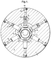
- FIG. 1 there is shown schematically in transverse cross-section a radial piston pump 1 for delivering fuel at high pressure to an output line for supplying an accumulator or the common rail of a common rail fuel injection system of an internal combustion engine.
- the pump 1 comprises six identical pumping sections 2.
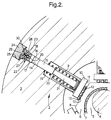
- a single pumping section 2 is shown in greater detail in Figure 2.
- the pumping sections 2 are located in a common body 3 in which is mounted a drive shaft 4 carrying an eccentric 5.
- a block 6 is mounted on the eccentric 5 by way of needle roller bearings 7.
- the block 6 presents a respective flat face 8 to each pumping section 2.
- Each pumping section 2 incorporates a tappet 9 having a tappet foot 10 which presents a flat face 11 to its associated block face 8.
- a multiplicity of needle rollers 12 are mounted between each tappet foot face 11 and its associated block face 8.
- Each set of needle roller 12 is mounted in a cage 13 and is located between lips provided on the edges of the tappet feet 10 and static guide plates provided at opposite ends of the block 6.
- the needle rollers 12 are effective to transfer forces perpendicular to the faces 8, 11 from the block to the tappets 9. However, because the rollers are in rolling contact with both the block face 8 and the tappet face 11, they do not transfer forces between the block 6 and the tappets 9 which are transverse to the axes of the tappets.
- the needle rollers may be mounted in retaining grooves in the block face or tappet faces rather than being mounted in the cage between the faces. However, if the needle rollers are located in grooves they will experience some sliding friction which does not occur when the needle rollers operate between flat faces as illustrated in Figure 1. Accordingly, the arrangement of Figure 1 is preferred.
- the pumping section 2 includes a cylinder 14 defined in the body 3 and an associated pump plunger 15 which is slidably mounted in the cylinder 14 to define a pumping chamber 16 located between the plunger 15 and the axially inner face 17 of a taper plug 18 which closes the radially out end of the cylinder 14.
- Each plunger 15 has associated with it a tappet 9 which is slidably mounted in a guide bore 19 provided in the body 3.
- the tappets 9 are each biased radially inwardly by a tappet spring 20.
- a tappet peg 21 is located within each tappet 9 by the tappet spring 20 and abuts its associated plunger 15 such that when the tappets 9 are driven radially outwardly by the eccentric 5 each tappet peg 21 drives its associated plunger 15 radially outwardly to reduce the volume of the pumping chamber 16 and deliver liquid via a non-return valve 22 provided in the taper plug 18 to an output line.
- each pumping chamber 16 When the above described pump is required to operate at maximum output volume each pumping chamber 16 is fully charged during each radially inward movement of its associated plunger 15 via a suitable filling line (not shown). Accordingly, at the commencement of each pumping stroke each respective plunger is at its radially innermost position and movement of the plunger from that position to its radially outermost position during its pumping stroke will deliver the maximum available volume to the output line.
- control means are provided for disabling some of the pumping chambers and for controlling the volume of fuel delivered during each pumping stroke by the remaining pumping chambers.
- control means are provided for simultaneously disabling three of the pumping sections (located at 120° relative to each other) and for controlling the output of the other pumping sections.
- means for disabling one set of pumping chambers means may be provided for controlling the output of those pumping chambers.
- simply disabling one or more pumping chambers and controlling the pumping volume of the remaining pumping chambers is relatively simple compared with controlling the volumetric output of all pumping chambers as well as disabling some of them, the former arrangement is preferred.
- means are provided for selectively preventing the flow of filling liquid to one set of three pumping chambers (located at 120° relative to each other) and for controlling the effective pumping volume of the remaining chambers.
- the effective pumping volume of the remaining chambers may be controlled either by controlling the supply of fluid to those chambers during the respective filling strokes thereof, or by spilling high pressure fluid from those chambers during delivery stroke of the associated plungers. Either arrangement provides significant improvements as compared with the prior art.
- the pump is considered to be operating at full output so that all pumping chambers are delivering the maximum available volume, and it is desired to reduce the volumetric output of the pump, the three chambers which can be disabled are, initially, permitted to continue pumping at full volumetric output whilst the remaining three chambers are controlled to progressively reduce the output volume from those chambers.
- the total output of the pump may be reduced from 100% to 50% by reducing the output for the controllable pumping chambers from 100% to 0%. If the total output of the pump is to be reduced to less than 50% of the maximum output of the pump the chambers which can be disabled are disabled, and the volumetric output of the chambers which can be controlled is progressively reduced from 100% to 0% in order to reduce the total pump output from 50% to 0%.
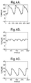
- Figures 3A, 3B and 3C and 4A, 4B and 4C show the total torque requirement for pumps having three large plungers (Figures 3A, 3B and 3C) and six small plungers (4A, 4B and 4C) operating at respectively 75% output ( Figures 3A and 4A), 50% output ( Figures 3B and 4B) and 25% output (3C and 4C).
- the cross-sectional area of the individual plungers of the pump of Figures 3A, 3B and 3C is twice that of the individual plungers of the pump of Figures 4A, 4B and 4C and accordingly the two pumps have the same total available maximum output volume (assuming the same plunger stroke and rotational speed).
- the pumping chamber 16 are closed by a particularly desirable sealing arrangement which also provides for particularly desirable housing of the non-return valve 22 in a manner which gives rise to a minimum of dead volume within the pumping chamber.
- Each pumping chamber 16 is closed by a taper plug 18 which is driven into sealing engagement with a mating taper 23 by means of a screw plug 24 which is in screw threaded engagement with a threaded bore 25 provided in the body 3.
- An axial bore 26 extends from the end face 17 of the taper plug 18 to a seat 27 of the non return valve 22.
- the valve member of the non return valve is constituted by a ball 28 which is located in a passage 29 which extends from the seat 27 to the radially outer end of the taper plug 18.
- the ball 28 is biased against its associated seat 27 by a spring which reacts against a shoulder provided on the plug 24.
- a suitable washer for example an iron washer 30, is provided between the screw plug 24 and the taper plug 18 to provide a fluid seal. Accordingly, sealing of the radially outer end of the pumping chamber 16 is effected by virtue of the taper fit of the plug 18 and the axial compression of the washer 30. Both the taper fit and the axial compression of the washer give rise to reliable fluid seals. Also, by positioning the non-return valve 30 in the tapered plug 18 a minimum of dead volume is provided upstream of the non return valve 22.
Landscapes
- Engineering & Computer Science (AREA)
- Mechanical Engineering (AREA)
- General Engineering & Computer Science (AREA)
- Details Of Reciprocating Pumps (AREA)
- Reciprocating Pumps (AREA)
Abstract
Description
- This invention relates to a radial piston pump, and more particularly to a radial piston pump suitable for delivering liquid at a high pressure and at a volumetric output rate which can be controlled independently of the speed of rotation of the pump drive shaft.
- An embodiment of the invention is particularly suitable for use as a fuel supply pump to supply high pressure fuel to an accumulator or directly to the common rail of a common rail fuel injection system for an internal combustion engine.
- Known radial piston pumps for fuel injection systems have a number of disadvantages if used to supply high pressure fuel to a accumulator or directly to the common rail of a common rail fuel injection system. In order to provide output at a rate which is as constant as possible under full load conditions a radial piston pump preferably comprises a multiplicity of long stroke pumping plungers which are operated by a common eccentric. For example, a radial piston pump with three pumping plungers located at 120° intervals relative to each other and driven by a common eccentric will deliver fuel at a combined rate which varies by about ± 7% from a steady value when operating at full stroke. The drive torque necessary to drive the plungers similarly varies by a relatively small percentage from a steady value. If a relatively lower volumetric rate of delivery for the same drive shaft rotational speed is required excess pumped fuel can be spilled through an appropriate spill valve. However, this procedure leads to a considerable wastage of energy. As an alternative, the inlets to the pumping chambers can be controlled so that the pumping chambers only partially fill during each fill stroke with the result that the pumped volume corresponds with the required output.However, with such a procedure the start of pumping for each plunger is retarded relative to the start point at full stroke and the combined rate output of the plungers, and the corresponding drive torque requirement, changes from the relatively smooth characteristic at full output to a progressively more saw-tooth-like shape as the controlled output reduces. The increasingly uneven output flow rate and drive torque requirement are both highly undesirable.
- According to one aspect of the present invention there is provided a radial piston pump comprising a multiplicity of radially extending cylinders each of which is provided with a radially movable pumping plunger to define, within the cylinder, a pumping chamber which may be increased in volume by a movement of its associated plunger in one direction to receive a liquid to be pumped and may be reduced in volume by movement of its associated plunger in the opposite direction to deliver liquid at high pressure to an output line, the pump comprising means for selectively disabling one or more pumping chambers so that the or each disabled pumping chamber delivers no pumped fluid to the output line.
- By selectively disabling one or more pumping chambers under certain operating conditions, the remaining pumping chambers continue to operate over a relatively large part of their stroke, as compared with the part of their stroke over which they would operate if all the pumping chambers were contributing to the particular level of volumetric output. This leads to a reduction in the variation of torque required to drive the pump. Disabling of one or more pumping chambers is preferably achieved by preventing the flow of liquid into the pumping chamber during what would normally be the filling stroke of the associated plunger. By this means, the pump plungers of the disabled pumping chambers will remain stationary at the position corresponding to the end of their pumping stroke when their associated pumping chamber is disabled.
- In a particularly preferred embodiment of the invention the pump is provided with six identical pumping chambers spaced apart circumferentially by 60° and driven by a common eccentric. Under full load conditions each pumping chamber is fully charged during each stroke of its associated plunger. As the required delivery volume progressively decreases from full load conditions the inlet to three of the pumping chambers, spaced 120° from each other, is progressively decreased whilst the remaining three pumping chambers continue to operate at full volume. When half load conditions are reached the delivery to the three controlled pump chambers will have been restricted to nothing and the entire delivery will be provided by the remaining three pumping chambers.
- A further problem associated with radial piston pumps operating at high pressures is that if a simple cam and cam follower arrangement is used for driving the pump plungers it become progressively more difficult to maintain adequate lubrication as delivery pressure increases. The higher the delivery pressure, the greater will be the force which the cam must exert and the greater will be the tendency for lubricating oil to be squeezed out from the interface between the cam and its follower or between the roller and shoe of the cam followers as the case may be.
- According to another aspect of the present invention a radial piston pump comprising a multiplicity of radially extending cylinders each of which houses a pump plunger which is driven by an eccentric provided on a drive shaft is provided with a block rotatably mounted on the eccentric and having a face corresponding to each of the cylinders; a tappet associated with each pump plunger, each tappet presenting a face to one of the faces of the block; and rotatable bearing elements interposed between each block face and its corresponding tappet face to support the tappet for transverse movement relative to its associated face of the block during operation of the pump.
- The rotatable bearing elements are preferably needle rollers mounted in a roller cage.
- Preferably, the block is mounted on the eccentric by way of rotatable bearing elements, for example needle roller bearings.
- According to a third aspect of the present invention the pumping chamber of a high pressure pump is closed by a means of a tapered plug which is located in a matching taper of a tapered region of a passage leading to the pumping chamber, the tapered plug being, in use, secured in position by a screw plug which is screw-threadedly engaged with screw threads provided in a portion of the passage located outwardly of the taped region.
- Preferably, the taper plug includes a passage which extends from a port which opens into the pumping chamber to a valve seat provided on the taper plug, and a valve element is biased into contact with the valve seat to provide a non-return valve permitting passage of liquid from the pumping chamber to an outlet connection down stream of the valve element. Preferably, the valve element is located in a bore in the taper plug which is closed to the exterior of the pump by the screw plug. Preferably, a washer is located between the screw plug and the taper plug to seal the valve member bore.
- With such an arrangement, an outlet valve to the pumping chamber can be provided within the tapered plug and the sealing of the pumping chamber to the exterior of the pump is effected by the taper between the taper plug and the tapered region of the passage in combination with a washer which is compressed between the screw plug and the taper plug. Such an arrangement provides particularly simple and effective sealing of the pumping chamber and facilitates ready access to the valve member for service purposes. The arrangement also provides an outlet valve arrangement which offers a very low level of dead volume in the pumping chamber.
- The above and further features of the advantage of the present invention become clear from the following description of a preferred embodiment thereof given by way of example only, reference being had to the accompanying drawings wherein
- Figure 1 is a schematic cross-sectional view through a preferred embodiment of radial piston pump according to the present invention;
- Figure 2 is an enlarged view of one of the pumping sections of the pump of Figure 1;
- Figures 3A, 3B and 3C show respectively the torque required to drive a pump having three large pump plungers at 75% output, 50% output and 25% output; and
- Figures 4A, 4B and 4C show respectively the torque required to drive a pump having six small pump plungers and a control arrangement in accordance with the present invention at 75% output, 50% output and 25% output.
- Referring firstly to Figure 1 there is shown schematically in transverse cross-section a radial piston pump 1 for delivering fuel at high pressure to an output line for supplying an accumulator or the common rail of a common rail fuel injection system of an internal combustion engine. The pump 1 comprises six
identical pumping sections 2. Asingle pumping section 2 is shown in greater detail in Figure 2. Thepumping sections 2 are located in acommon body 3 in which is mounted adrive shaft 4 carrying an eccentric 5. Ablock 6 is mounted on the eccentric 5 by way of needle roller bearings 7. Theblock 6 presents a respectiveflat face 8 to eachpumping section 2. Eachpumping section 2 incorporates atappet 9 having atappet foot 10 which presents aflat face 11 to its associatedblock face 8. A multiplicity ofneedle rollers 12 are mounted between eachtappet foot face 11 and its associatedblock face 8. Each set ofneedle roller 12 is mounted in acage 13 and is located between lips provided on the edges of thetappet feet 10 and static guide plates provided at opposite ends of theblock 6. - The
needle rollers 12 are effective to transfer forces perpendicular to thefaces tappets 9. However, because the rollers are in rolling contact with both theblock face 8 and thetappet face 11, they do not transfer forces between theblock 6 and thetappets 9 which are transverse to the axes of the tappets. - If desired, the needle rollers may be mounted in retaining grooves in the block face or tappet faces rather than being mounted in the cage between the faces. However, if the needle rollers are located in grooves they will experience some sliding friction which does not occur when the needle rollers operate between flat faces as illustrated in Figure 1. Accordingly, the arrangement of Figure 1 is preferred.
- Referring now to Figure 2, one
pumping section 2 is illustrated in detail. Thepumping section 2 includes acylinder 14 defined in thebody 3 and an associatedpump plunger 15 which is slidably mounted in thecylinder 14 to define apumping chamber 16 located between theplunger 15 and the axiallyinner face 17 of ataper plug 18 which closes the radially out end of thecylinder 14. Eachplunger 15 has associated with it atappet 9 which is slidably mounted in aguide bore 19 provided in thebody 3. Thetappets 9 are each biased radially inwardly by atappet spring 20. Atappet peg 21 is located within eachtappet 9 by thetappet spring 20 and abuts its associatedplunger 15 such that when thetappets 9 are driven radially outwardly by the eccentric 5 eachtappet peg 21 drives itsassociated plunger 15 radially outwardly to reduce the volume of thepumping chamber 16 and deliver liquid via anon-return valve 22 provided in thetaper plug 18 to an output line. - When the above described pump is required to operate at maximum output volume each
pumping chamber 16 is fully charged during each radially inward movement of its associatedplunger 15 via a suitable filling line (not shown). Accordingly, at the commencement of each pumping stroke each respective plunger is at its radially innermost position and movement of the plunger from that position to its radially outermost position during its pumping stroke will deliver the maximum available volume to the output line. In order to reduce the volumetric output of the pump (for a given speed of drive shaft rotation) as compared with the maximum available, control means are provided for disabling some of the pumping chambers and for controlling the volume of fuel delivered during each pumping stroke by the remaining pumping chambers. In the preferred embodiment of the invention, in which there are six pumping sections, control means are provided for simultaneously disabling three of the pumping sections (located at 120° relative to each other) and for controlling the output of the other pumping sections. In an alternative embodiment, in addition to means for disabling one set of pumping chambers, means may be provided for controlling the output of those pumping chambers. However, since simply disabling one or more pumping chambers and controlling the pumping volume of the remaining pumping chambers is relatively simple compared with controlling the volumetric output of all pumping chambers as well as disabling some of them, the former arrangement is preferred. - To this end, in the preferred embodiment, means are provided for selectively preventing the flow of filling liquid to one set of three pumping chambers (located at 120° relative to each other) and for controlling the effective pumping volume of the remaining chambers. The effective pumping volume of the remaining chambers may be controlled either by controlling the supply of fluid to those chambers during the respective filling strokes thereof, or by spilling high pressure fluid from those chambers during delivery stroke of the associated plungers. Either arrangement provides significant improvements as compared with the prior art.
- If the pump is considered to be operating at full output so that all pumping chambers are delivering the maximum available volume, and it is desired to reduce the volumetric output of the pump, the three chambers which can be disabled are, initially, permitted to continue pumping at full volumetric output whilst the remaining three chambers are controlled to progressively reduce the output volume from those chambers. By this means, the total output of the pump may be reduced from 100% to 50% by reducing the output for the controllable pumping chambers from 100% to 0%. If the total output of the pump is to be reduced to less than 50% of the maximum output of the pump the chambers which can be disabled are disabled, and the volumetric output of the chambers which can be controlled is progressively reduced from 100% to 0% in order to reduce the total pump output from 50% to 0%.
- For a full understanding of the present invention reference should be had to Figures 3A, 3B and 3C and 4A, 4B and 4C which show the total torque requirement for pumps having three large plungers (Figures 3A, 3B and 3C) and six small plungers (4A, 4B and 4C) operating at respectively 75% output (Figures 3A and 4A), 50% output (Figures 3B and 4B) and 25% output (3C and 4C). The cross-sectional area of the individual plungers of the pump of Figures 3A, 3B and 3C is twice that of the individual plungers of the pump of Figures 4A, 4B and 4C and accordingly the two pumps have the same total available maximum output volume (assuming the same plunger stroke and rotational speed).
- Looking firstly at Figures 3A and 4A, when a pump having three large plungers is operated by throttling the filling of each pumping chamber to provide a total output equal to 75% maximum, the required torque to drive the pump has a pronounced saw-tooth profile and varies from 0 to nearly 40 Nm three times during each rotation of the shaft. To achieve the same level of output (75%) in the case of the present invention three of the pumping chambers will continue to operate at their full volume, whilst the remaining three will operate at half their available volume. This will produce the required torque levels illustrated in Figures 4A. It will be noted that the torque has a less pronounced saw-tooth profile and that the torque level required remains positive and varies from just above 10 Nm to just below 40 Nm.
- Looking now at Figures 3B and 4B, the combined torque at a total of 50% output is shown. In the case of a three plunger pump each pumping chamber is charged to half its available volume during the filling stroke and the total combined operating torque required is shown in Figure 3B. In the case of the embodiment of the present invention three of the pumping chambers will continue to be charged to their maximum available volume whilst three of the pumping chambers will not be charged at all. This gives rise to the combined torque requirement illustrated in Figure 4B. It will be noted that Figure 4B represents a dramatically better torque characteristic than Figure 3B.
- Finally, considering Figures 3C and 4C the combined torque requirements for a pump operating at 25% total output is shown. In the case of a three plunger pump a very pronounced saw-tooth profile is required with substantially no torque required during a substantial proportion of each rotation of the shaft, and the maximum torque required still being in excess of 30 Nm. Note also the rapid rise from zero to maximum torque. In contrast, in the arrangement of the present invention in which, to deliver 25% output, three of the pumping chambers are disabled and the remaining three pumping chambers operating at 50% volume, the required driving torque is as shown in Figure 4C. Comparing Figures 3C and 4C it will be noted that the proportion of each revolution during which no torque is required is much smaller in the case of the present invention, and the total maximum torque required in the case of the embodiment of the present invention is slightly less than 20 Nm as compared with slightly more than 30 Nm in the case of the prior art.
- Referring again to Figure 2 the
pumping chamber 16 are closed by a particularly desirable sealing arrangement which also provides for particularly desirable housing of thenon-return valve 22 in a manner which gives rise to a minimum of dead volume within the pumping chamber. - Each pumping
chamber 16 is closed by ataper plug 18 which is driven into sealing engagement with amating taper 23 by means of ascrew plug 24 which is in screw threaded engagement with a threadedbore 25 provided in thebody 3. Anaxial bore 26 extends from theend face 17 of thetaper plug 18 to aseat 27 of thenon return valve 22. The valve member of the non return valve is constituted by aball 28 which is located in apassage 29 which extends from theseat 27 to the radially outer end of thetaper plug 18. - The
ball 28 is biased against its associatedseat 27 by a spring which reacts against a shoulder provided on theplug 24. A suitable washer, for example aniron washer 30, is provided between thescrew plug 24 and thetaper plug 18 to provide a fluid seal. Accordingly, sealing of the radially outer end of the pumpingchamber 16 is effected by virtue of the taper fit of theplug 18 and the axial compression of thewasher 30. Both the taper fit and the axial compression of the washer give rise to reliable fluid seals. Also, by positioning thenon-return valve 30 in the tapered plug 18 a minimum of dead volume is provided upstream of thenon return valve 22.
Claims (10)
- A radial piston pump(1) comprising a multiplicity of radially extending cylinders (14) each of which is provided with a radially movable pumping plunger(15) to define, within the cylinder, a pumping chamber(16) which may be increased in volume by a movement of its associated plunger(15) in one direction to receive a liquid to be pumped and may be reduced in volume by movement of its associated plunger(15) in the opposite direction to deliver liquid at high pressure to an output line, the pump(1) comprising means for selectively disabling one or more of the pumping chambers(16) so that the or each disabled pumping chamber delivers no pumped fluid to the output line.
- A radial piston pump as claimed in claim 1, wherein the means for selectively disabling one or more of the pumping chambers(16) comprises means for preventing the flow of liquid into a pumping chamber during what would normally be the filling stroke of the associated plunger.
- A radial piston pump as claimed in claim 1 or 2, wherein six identical pumping chambers(16) are spaced apart circumferentially by 60° and driven by a common eccentric(5).
- A radial piston pump(1) comprising a multiplicity of radially extending cylinders(14) each of which houses a pump plunger(15) which is driven by an eccentric(5) provided on a drive shaft(4); a block(6)rotatably mounted on the eccentric(5) and having a face(8) corresponding to each of the cylinders (14); a tappet(9) associated with each pump plunger(15), each tappet(9) presenting a face(11) to one of the faces(8) of the block; and rotatable bearing elements(12) interposed between each block face(8) and its corresponding tappet face(11) to support the tappet(9) for transverse movement relative to its associated face of the block(6) during operation of the pump.
- A radial piston pump as claimed in claim 4, wherein the rotatable bearing elements(12) are needle rollers mounted in a roller cage.
- A radial piston pump as claimed in claim 4 or 5, wherein the block(6) is mounted on the eccentric(5) by way of rotatable bearing elements(7), for example needle roller bearings.
- A pump comprising a pumping chamber(16) closed by means of a taper plug(18) which is located in a matching taper of a tapered region of a passage leading to the pumping chamber(16), the taper plug(18) being, in use, secured in position by a screw plug(24) which is screw-threadedly engaged with screw threads provided in a portion of the passage located outwardly of the taped region.
- A pump as claimed in claim 7, wherein the taper plug(18) includes a passage(26) which extends from a port which opens into the pumping chamber(16) to a valve seat(27) provided on the taper plug(18), and a valve element(28) biased into contact with the valve seat(27) to provide a non-return valve permitting passage of liquid from the pumping chamber(16) to an outlet connection downstream of the valve element.
- A pump as claimed in claim 8. wherein the valve element(28) is located in a bore(29) in the taper plug(18) which is closed to the exterior of the pump by the screw plug(24).
- A pump as claimed in claim 9, wherein a washer(30) is located between the screw plug(24) and the taper plug(18) to seal the valve member bore.
Applications Claiming Priority (2)
| Application Number | Priority Date | Filing Date | Title |
|---|---|---|---|
| GB9610785 | 1996-05-23 | ||
| GBGB9610785.9A GB9610785D0 (en) | 1996-05-23 | 1996-05-23 | Radial piston pump |
Publications (3)
| Publication Number | Publication Date |
|---|---|
| EP0809023A2 true EP0809023A2 (en) | 1997-11-26 |
| EP0809023A3 EP0809023A3 (en) | 1999-04-07 |
| EP0809023B1 EP0809023B1 (en) | 2003-09-10 |
Family
ID=10794184
Family Applications (1)
| Application Number | Title | Priority Date | Filing Date |
|---|---|---|---|
| EP97303308A Expired - Lifetime EP0809023B1 (en) | 1996-05-23 | 1997-05-15 | Radial piston pump |
Country Status (4)
| Country | Link |
|---|---|
| US (1) | US5823091A (en) |
| EP (1) | EP0809023B1 (en) |
| DE (1) | DE69724695T2 (en) |
| GB (1) | GB9610785D0 (en) |
Cited By (4)
| Publication number | Priority date | Publication date | Assignee | Title |
|---|---|---|---|---|
| EP0939222A2 (en) | 1998-02-27 | 1999-09-01 | LUCAS INDUSTRIES public limited company | Fuel pump |
| WO1999061796A1 (en) * | 1998-05-26 | 1999-12-02 | Caterpillar Inc. | Hydraulic system having a variable delivery pump |
| WO2000019095A1 (en) * | 1998-09-28 | 2000-04-06 | Robert Bosch Gmbh | Radial piston pump |
| GB2414523A (en) * | 2004-05-28 | 2005-11-30 | Stanadyne Corp | Radial piston pump with eccentrically driven rolling actuation ring |
Families Citing this family (16)
| Publication number | Priority date | Publication date | Assignee | Title |
|---|---|---|---|---|
| DE19753593A1 (en) * | 1997-12-03 | 1999-06-17 | Bosch Gmbh Robert | Radial piston pump for high-pressure fuel supply |
| DE19802475A1 (en) * | 1998-01-23 | 1999-07-29 | Bosch Gmbh Robert | Radial piston pump to supply fuel at high pressure for fuel injection system of internal combustion engine |
| US6286836B1 (en) * | 1999-02-02 | 2001-09-11 | American Roller Company | Sealed charging port and method of charging for a heat pipe roller |
| GB9903115D0 (en) * | 1999-02-11 | 1999-04-07 | Lucas Ind Plc | Multi-chamber positive displacement pump |
| US6461117B2 (en) * | 2001-02-27 | 2002-10-08 | International Truck Intellectual Property Company, L.L.C. | Reversible volume oil pump |
| DE10249818B4 (en) * | 2002-10-24 | 2005-10-20 | Daimler Chrysler Ag | Surface of a body on which another body in a preferred sliding direction against each other can be slidably arranged |
| DE102007019261A1 (en) | 2007-04-17 | 2008-10-23 | Golle Motor Ag | Radial piston pump, esp. For Common Rail (CR) injection systems |
| US8020399B2 (en) * | 2007-04-17 | 2011-09-20 | T&B Financial Services, Inc. | High pressure mister fan cooling system |
| US7861682B2 (en) * | 2007-10-25 | 2011-01-04 | Ford Global Technologies, Llc | Systems and methods for managing camshaft torsional loading |
| GB201202221D0 (en) * | 2012-02-09 | 2012-03-28 | Delphi Tech Holding Sarl | Improvements relating to fuel pumps |
| EP2628942B1 (en) * | 2012-02-14 | 2014-10-01 | Continental Automotive GmbH | Pump and common rail fuel injection system |
| CN103758721B (en) * | 2013-10-18 | 2016-02-24 | 西安交通大学 | A kind of axial-flow type biserial radial plunger hydraulic pump |
| GB2532964B (en) * | 2014-12-03 | 2017-01-11 | Delphi Int Operations Luxembourg Sarl | High pressure fuel pump |
| CN115045817A (en) * | 2022-07-01 | 2022-09-13 | 北京天玛智控科技股份有限公司 | Piston Pump |
| CN116727171B (en) * | 2023-04-28 | 2025-10-17 | 云南浩鑫铝箔有限公司 | Aluminum foil paper lubricating device |
| CN117145718B (en) * | 2023-10-16 | 2024-01-23 | 深海装备科技(徐州)有限公司 | Ultrahigh-pressure radial plunger pump |
Family Cites Families (9)
| Publication number | Priority date | Publication date | Assignee | Title |
|---|---|---|---|---|
| US2941475A (en) * | 1957-05-24 | 1960-06-21 | Dynex Inc | Hydraulic pump |
| US3178888A (en) * | 1963-04-15 | 1965-04-20 | George R Soseman | Plural output pump |
| US3682565A (en) * | 1970-08-31 | 1972-08-08 | Donald L Yarger | Multiple piston pump apparatus |
| US4482300A (en) * | 1982-05-17 | 1984-11-13 | Caterpillar Tractor Co. | Reversible pump coupling apparatus |
| EP0119211B1 (en) * | 1982-09-17 | 1986-11-20 | HIRMANN, Georg | Motor mechanism driven by a pressure device |
| DE3517521A1 (en) * | 1985-05-15 | 1986-11-20 | Robert Bosch Gmbh, 7000 Stuttgart | FUEL INJECTION PUMP |
| DE3637174A1 (en) * | 1986-10-31 | 1988-05-05 | Rexroth Mannesmann Gmbh | Piston engine with changeable displacement |
| US5032065A (en) * | 1988-07-21 | 1991-07-16 | Nissan Motor Co., Ltd. | Radial piston pump |
| FI104014B1 (en) * | 1994-05-18 | 1999-10-29 | Valmet Voimansiirto Oy | Radial piston hydraulic motor and method for controlling a radial piston hydraulic motor |
-
1996
- 1996-05-23 GB GBGB9610785.9A patent/GB9610785D0/en active Pending
-
1997
- 1997-05-15 DE DE69724695T patent/DE69724695T2/en not_active Expired - Lifetime
- 1997-05-15 EP EP97303308A patent/EP0809023B1/en not_active Expired - Lifetime
- 1997-05-23 US US08/863,072 patent/US5823091A/en not_active Expired - Lifetime
Cited By (7)
| Publication number | Priority date | Publication date | Assignee | Title |
|---|---|---|---|---|
| EP0939222A2 (en) | 1998-02-27 | 1999-09-01 | LUCAS INDUSTRIES public limited company | Fuel pump |
| WO1999061796A1 (en) * | 1998-05-26 | 1999-12-02 | Caterpillar Inc. | Hydraulic system having a variable delivery pump |
| WO2000019095A1 (en) * | 1998-09-28 | 2000-04-06 | Robert Bosch Gmbh | Radial piston pump |
| GB2414523A (en) * | 2004-05-28 | 2005-11-30 | Stanadyne Corp | Radial piston pump with eccentrically driven rolling actuation ring |
| GB2414523B (en) * | 2004-05-28 | 2009-05-06 | Stanadyne Corp | Radial piston pump with eccentrically driven rolling actuation ring |
| US7950905B2 (en) | 2004-05-28 | 2011-05-31 | Stanadyne Corporation | Radial piston fuel supply pump |
| US8007251B2 (en) | 2004-05-28 | 2011-08-30 | Stanadyne Corporation | Radial piston fuel supply pump |
Also Published As
| Publication number | Publication date |
|---|---|
| DE69724695T2 (en) | 2004-07-15 |
| EP0809023B1 (en) | 2003-09-10 |
| US5823091A (en) | 1998-10-20 |
| DE69724695D1 (en) | 2003-10-16 |
| GB9610785D0 (en) | 1996-07-31 |
| EP0809023A3 (en) | 1999-04-07 |
Similar Documents
| Publication | Publication Date | Title |
|---|---|---|
| US5823091A (en) | Radial piston pump having means for selectively disabling at least one of the pumping chambers | |
| CN101715507B (en) | Lubricating apparatus and method for dosing cylinder lubricating oil | |
| US7108491B2 (en) | High pressure pump | |
| US6345609B1 (en) | Supply pump for gasoline common rail | |
| US5888054A (en) | Fuel pump having dual profile cam ring for driving low and high pressure reciprocating plungers | |
| US8007251B2 (en) | Radial piston fuel supply pump | |
| KR101559335B1 (en) | Improvements to fuel pumps | |
| EP0856661A2 (en) | Fuel pump | |
| US6799953B2 (en) | Port plate for an axial piston pump | |
| WO1998058172A1 (en) | Radial piston pump | |
| US20240263626A1 (en) | Hydraulic Linkage Plunger Pushing Mechanism and Plunger Diaphragm Pump Using Same | |
| EP0972936A2 (en) | Positive displacement pumps | |
| US6889665B2 (en) | High pressure pump for a fuel system of an internal combustion engine, and a fuel system and internal combustion engine employing the pump | |
| US6261069B1 (en) | Shaft seal with pressure equalizing shuttle | |
| US20020044873A1 (en) | High pressure fuel pump | |
| US5980214A (en) | Fluid pump with split plungers | |
| EP2189658B1 (en) | Fluid Pump Assembly | |
| EP1363016A2 (en) | Fuel pump | |
| GB2172339A (en) | Lubrication in a fuel pump | |
| EP1489301B1 (en) | Drive arrangement for a pump | |
| GB2309270A (en) | Radial plunger pump | |
| JP2001280220A (en) | High pressure fuel pump | |
| WO1999036686A1 (en) | Hydraulic pump with engine mounted drive bearing | |
| WO1992016738A1 (en) | Fuel injection pump | |
| US6974312B2 (en) | Pumping element for hydraulic pump |
Legal Events
| Date | Code | Title | Description |
|---|---|---|---|
| PUAI | Public reference made under article 153(3) epc to a published international application that has entered the european phase |
Free format text: ORIGINAL CODE: 0009012 |
|
| AK | Designated contracting states |
Kind code of ref document: A2 Designated state(s): DE ES FR GB IT |
|
| RHK1 | Main classification (correction) |
Ipc: F04B 1/06 |
|
| PUAL | Search report despatched |
Free format text: ORIGINAL CODE: 0009013 |
|
| AK | Designated contracting states |
Kind code of ref document: A3 Designated state(s): DE ES FR GB IT |
|
| 17P | Request for examination filed |
Effective date: 19990419 |
|
| RAP1 | Party data changed (applicant data changed or rights of an application transferred) |
Owner name: LUCAS INDUSTRIES LIMITED |
|
| RAP1 | Party data changed (applicant data changed or rights of an application transferred) |
Owner name: DELPHI TECHNOLOGIES, INC. |
|
| 17Q | First examination report despatched |
Effective date: 20020821 |
|
| GRAH | Despatch of communication of intention to grant a patent |
Free format text: ORIGINAL CODE: EPIDOS IGRA |
|
| GRAS | Grant fee paid |
Free format text: ORIGINAL CODE: EPIDOSNIGR3 |
|
| GRAA | (expected) grant |
Free format text: ORIGINAL CODE: 0009210 |
|
| AK | Designated contracting states |
Kind code of ref document: B1 Designated state(s): DE ES FR GB IT |
|
| PG25 | Lapsed in a contracting state [announced via postgrant information from national office to epo] |
Ref country code: IT Free format text: LAPSE BECAUSE OF FAILURE TO SUBMIT A TRANSLATION OF THE DESCRIPTION OR TO PAY THE FEE WITHIN THE PRE;WARNING: LAPSES OF ITALIAN PATENTS WITH EFFECTIVE DATE BEFORE 2007 MAY HAVE OCCURRED AT ANY TIME BEFORE 2007. THE CORRECT EFFECTIVE DATE MAY BE DIFFERENT FROM THE ONE RECORDED.SCRIBED TIME-LIMIT Effective date: 20030910 Ref country code: FR Free format text: LAPSE BECAUSE OF FAILURE TO SUBMIT A TRANSLATION OF THE DESCRIPTION OR TO PAY THE FEE WITHIN THE PRESCRIBED TIME-LIMIT Effective date: 20030910 |
|
| REG | Reference to a national code |
Ref country code: GB Ref legal event code: FG4D |
|
| REF | Corresponds to: |
Ref document number: 69724695 Country of ref document: DE Date of ref document: 20031016 Kind code of ref document: P |
|
| PG25 | Lapsed in a contracting state [announced via postgrant information from national office to epo] |
Ref country code: ES Free format text: LAPSE BECAUSE OF FAILURE TO SUBMIT A TRANSLATION OF THE DESCRIPTION OR TO PAY THE FEE WITHIN THE PRESCRIBED TIME-LIMIT Effective date: 20031221 |
|
| PG25 | Lapsed in a contracting state [announced via postgrant information from national office to epo] |
Ref country code: GB Free format text: LAPSE BECAUSE OF NON-PAYMENT OF DUE FEES Effective date: 20040515 |
|
| PLBE | No opposition filed within time limit |
Free format text: ORIGINAL CODE: 0009261 |
|
| STAA | Information on the status of an ep patent application or granted ep patent |
Free format text: STATUS: NO OPPOSITION FILED WITHIN TIME LIMIT |
|
| 26N | No opposition filed |
Effective date: 20040614 |
|
| EN | Fr: translation not filed | ||
| GBPC | Gb: european patent ceased through non-payment of renewal fee |
Effective date: 20040515 |
|
| PGFP | Annual fee paid to national office [announced via postgrant information from national office to epo] |
Ref country code: DE Payment date: 20120529 Year of fee payment: 16 |
|
| PG25 | Lapsed in a contracting state [announced via postgrant information from national office to epo] |
Ref country code: DE Free format text: LAPSE BECAUSE OF NON-PAYMENT OF DUE FEES Effective date: 20131203 |
|
| REG | Reference to a national code |
Ref country code: DE Ref legal event code: R119 Ref document number: 69724695 Country of ref document: DE Effective date: 20131203 |