EP0808965A2 - Form for making arched openings in walls - Google Patents
Form for making arched openings in walls Download PDFInfo
- Publication number
- EP0808965A2 EP0808965A2 EP97103435A EP97103435A EP0808965A2 EP 0808965 A2 EP0808965 A2 EP 0808965A2 EP 97103435 A EP97103435 A EP 97103435A EP 97103435 A EP97103435 A EP 97103435A EP 0808965 A2 EP0808965 A2 EP 0808965A2
- Authority
- EP
- European Patent Office
- Prior art keywords
- formwork
- strut
- support strut
- support
- formlining
- Prior art date
- Legal status (The legal status is an assumption and is not a legal conclusion. Google has not performed a legal analysis and makes no representation as to the accuracy of the status listed.)
- Granted
Links
- 238000009415 formwork Methods 0.000 claims abstract description 44
- 238000004519 manufacturing process Methods 0.000 claims abstract description 5
- 229910000831 Steel Inorganic materials 0.000 claims description 5
- 239000010959 steel Substances 0.000 claims description 5
- 239000004033 plastic Substances 0.000 claims description 4
- 229920003023 plastic Polymers 0.000 claims description 4
- 239000002023 wood Substances 0.000 claims description 4
- 239000004800 polyvinyl chloride Substances 0.000 claims description 3
- 238000010276 construction Methods 0.000 description 3
- 239000000463 material Substances 0.000 description 3
- 238000011065 in-situ storage Methods 0.000 description 2
- 239000002184 metal Substances 0.000 description 1
Images


Classifications
-
- E—FIXED CONSTRUCTIONS
- E04—BUILDING
- E04G—SCAFFOLDING; FORMS; SHUTTERING; BUILDING IMPLEMENTS OR AIDS, OR THEIR USE; HANDLING BUILDING MATERIALS ON THE SITE; REPAIRING, BREAKING-UP OR OTHER WORK ON EXISTING BUILDINGS
- E04G21/00—Preparing, conveying, or working-up building materials or building elements in situ; Other devices or measures for constructional work
- E04G21/14—Conveying or assembling building elements
- E04G21/16—Tools or apparatus
- E04G21/18—Adjusting tools; Templates
- E04G21/1841—Means for positioning building parts or elements
-
- E—FIXED CONSTRUCTIONS
- E04—BUILDING
- E04G—SCAFFOLDING; FORMS; SHUTTERING; BUILDING IMPLEMENTS OR AIDS, OR THEIR USE; HANDLING BUILDING MATERIALS ON THE SITE; REPAIRING, BREAKING-UP OR OTHER WORK ON EXISTING BUILDINGS
- E04G15/00—Forms or shutterings for making openings, cavities, slits, or channels
-
- E—FIXED CONSTRUCTIONS
- E04—BUILDING
- E04G—SCAFFOLDING; FORMS; SHUTTERING; BUILDING IMPLEMENTS OR AIDS, OR THEIR USE; HANDLING BUILDING MATERIALS ON THE SITE; REPAIRING, BREAKING-UP OR OTHER WORK ON EXISTING BUILDINGS
- E04G21/00—Preparing, conveying, or working-up building materials or building elements in situ; Other devices or measures for constructional work
- E04G21/14—Conveying or assembling building elements
- E04G21/16—Tools or apparatus
- E04G21/18—Adjusting tools; Templates
- E04G21/1841—Means for positioning building parts or elements
- E04G21/1858—Templates for window or door openings, e.g. in a masonry wall
- E04G21/1866—Templates for window or door openings, e.g. in a masonry wall for making arches
Definitions
- the invention relates to a formwork device for the production of arcuate boundaries of wall recesses with a support device for a formwork skin.
- the object of the invention is to provide a formwork device for arches, with which all types of arches common in construction can be produced quickly and precisely.
- the object of the invention is achieved by means of a central vertical and preferably telescopically adjustable support strut and two pivotable holder arms projecting laterally on both sides of this support strut, each with a lower and upper cross strut, which together with connecting elements form a parallelogram at the ends and which together with the vertical support strut Wear elastically deformable formlining, loosened.
- round arches, basket arches, pointed arches and segment arches in all radii as well as isosceles and isosceles arches can be produced.
- the production of vaults by joining several elements is also possible.
- the holder arms according to the invention have clamps at their free ends which are always at an angle to the vertical support. Thanks to the parallel struts of the parallelogram of the holder arms, a perfect radius determination of all types of bends is always guaranteed. The ability to move the lower cross strut and various formlining clamps make it possible to cover all inclinations and types of bends with one and the same formwork device.
- spans of 60 cm to 1.60 m can be produced without changing the system.
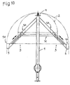
- FIG. 1 shows a schematic elevation of an apparatus according to the invention
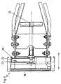
- FIG. 2 shows view B of FIG. 1
- Fig. 3 shows view A of Fig. 1
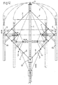
- Fig. 4 shows schematically the setting of the device for a pointed arch
- 5 shows a side view of the formwork skin in the area of the clamp
- FIGS. 6 to 8 schematically show elevations of the formwork device according to the invention for producing different arches.
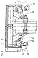
- the essential parts of the formwork device according to the invention are the vertical support strut 1, the formlining 2 and the two protruding laterally from the support strut 1 Retaining arms 3.
- the formwork skin 2 is elastic, but has sufficient internal stress to support the in-situ concrete or masonry that rests on it. Suitable materials for the formlining 2 are PVC, plastics, steel, wood.
- the formlining 2 is held by clamps 4, 5 both at the top of the vertical support strut 1 and at the free ends of the holding arms 3. Instead of the clamp 4, however, a fixed connection between the formlining 2 and the support strut 1 could also be provided.
- Each of the two holding arms 3 is formed by lower cross struts 6 and upper cross struts 7, which together with holding plates 8, 9, form a parallelogram.
- the holding plates 8 are fastened to the vertical support strut 1 by means of a flange 10 and a tension clamp 11.
- the upper cross struts 7 are supported by bolts 12 in the holding plates 8.
- the lower cross strut 6 is supported by a pin 13 in a circular guide 14 in the respective holding plate 8, the circular guide 14 being formed, for example, by a slot.
- the holding plates 9 are created by means of axes 15 on the lower and on the upper cross strut 6, 7.
- a support plate 16, which carries the clamp 5, is rotatably mounted on each holding plate 9.
- the clamps 4, 5 have U-shaped brackets 17, 18 which encompass the formlining 2. On the side webs of the U-shaped bracket 17, 18 inwardly directed hooks 19, 20 are formed, on which clamping parts 21, 22 engage.
- the clamping parts 22 are formed by a clamping bar 23 and a clamping screw 24.
- the clamping screw 24 By turning the clamping screw 24, the clamping bars 23 are moved in the direction of the double arrow of FIG. 3, whereby the formwork skin 2 is either clamped or released.
- the clamping parts 21 are formed by rotatable levers 25 which can be pivoted in the direction of the double arrow of FIG. 2 by means of screws 26 which are supported on abutments 27, as a result of which the bracket 17 is either clamped or released.
- 1 shows the formwork device set for formwork of a round arch.
- the formwork device according to the invention is converted for use in formwork of a segment arch.
- a split formlining 2 ' is preferably used, which is held at the tip of the support strut 1 by holding parts 28 which are connected in a hinge-like manner via a joint 29.
- the formwork device according to the invention can be arranged between vertically aligned formwork panels which laterally limit the sheet to be produced.
- vertical supports 30 can be provided, which form the outer limits for the arch.
- a further display plate with a scale can be provided, by means of which the precise angle setting of the holding arms 3 can be adjusted.
- the formlining 2 in the area of the clamp 5 can facilitate a scale 31 or holding arms 3 and thus the adjustment of the radius of the arc.
- the object of the invention is based on the principle that a formwork skin suitable for this is held by 3 pieces of clamps at the top, left and right. Due to the fixed clamping of the formwork skin at the 3 clamps and through a displaceability of the support arms along the middle support as well as a displaceability of the horizontal strut, every type of arch can be manufactured quickly and precisely. Additional arrangement of the formwork skin is no longer necessary due to the arrangement of the 3 clamps.
- Wood, plastic or metal can be used as the material for the formwork skin.
- plan 1051A40 instead of the swivel arms arranged as a parallelogram, as shown in plan 1051A40, individual support arms, scissor-shaped (plan 1053A40) and open parallelograms (plan 1054A40), which are either fixed or slidably connected to the center support, can be used.
- the holding arms can be attached to the upper end of the support by inverting the basic principle.
- the multi-functionality is achieved through the adjustability of the lateral holding arms and the horizontal support.
- the side swivel arms are now loaded on "train", a correspondingly dimensioned chain is preferably used as the holding mechanism or an adjustable sliding arm is used according to plan 1052A40.
- the various arch radii and spans are achieved by the telescopically adjustable horizontal strut (plan 1051A40).
- the holding arms according to the invention hold clamps at their free ends, which are always at an angle to the vertical support. Due to the displaceable cross struts of the holding arms or the horizontal alignment of the cross strut when using the individual support, a perfect radius determination of all types of bends is always guaranteed. Due to the possibility to move the horizontal cross strut as well as the holding arms, as well as various formlining clamps, it is possible to cover all inclinations and arch types with one and the same formwork device.
- spans of 0.60 m to 1.60 m can be produced without changing the system.
- conventional steel supports such as are used on construction sites, are used for the vertical support strut.
- supports made especially for the purpose of support, in particular those with a central guide for moving the horizontal strut, can also be used.
- the essential parts of the formwork device according to the invention are the vertical support strut 1, the formwork skin, the formwork skin 2 and the two displaceable holding arms 3 projecting laterally from the support strut 1.
- the formwork skin 2 is elastic, but has sufficient internal stress to support the in-situ concrete or Bear masonry. Suitable materials for the formlining 2 are PVC, plastics, steel and wood.
- the formlining 2 is held by clamps 4 both at the top of the vertical support strut 1 and at the free ends of the holding arms 3. Instead of the clamp 4, however, a fixed connection between the formlining 2 and the support strut 1 could also be provided.
- Each of the two holding arms 3 is held by adjustable support devices 5, which together with the formwork clamp 4 form the arch structure.
- the holding arms 3 are attached to the vertical support strut 1.
- a formwork clamp 4 is rotatably or permanently mounted.
- the terminals 4 are designed as in VARINATE A.
- Plan 1051A40 shows the formwork device set for formwork of a round arch.
- the formwork device according to the invention can be arranged between vertically aligned formwork panels which laterally delimit the sheet to be produced.
Landscapes
- Engineering & Computer Science (AREA)
- Architecture (AREA)
- Mechanical Engineering (AREA)
- Civil Engineering (AREA)
- Structural Engineering (AREA)
- Forms Removed On Construction Sites Or Auxiliary Members Thereof (AREA)
Abstract
Bei einer Schalungsvorrichtung zur Herstellung von bogenförmigen Begrenzungen von Wandaussparungen mit Sützeinrichtungen für eine Schalhaut (2) sind eine mittlere vertikale, teleskopisch verstellbare Stützstrebe (1) und zwei an beiden Seiten von der Stützstreben (1) seitlich abstehende, verschiebbar oder schwenkbare Haltearme (3) vorgesehen. Die Haltearme (3) bilden jeweils ein Parallelogramm oder bestehen aus einzelnen teleskopartigen Streben. Am oberen Ende der Stützstrebe (1) befestigte Ketten stützen zusammen mit der vertikalen Stützstrebe (1) die Haltearme (3), wodurch die elastisch verformbare Schalhaut (2) in der eingestellten Form und Spannweite eines Bogens von nur drei Stützeinrichtungen getragen wird.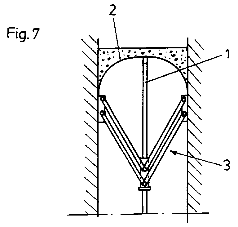
Description
Die Erfindung bezieht sich auf eine Schalungsvorrichtung zur Herstellung von bogenförmigen Begrenzungen von Wandaussparungen mit Stützeinrichtung für eine Schalhaut.The invention relates to a formwork device for the production of arcuate boundaries of wall recesses with a support device for a formwork skin.
Aufgabe der Erfindung ist es, eine Schalungsvorrichtung für Bögen zu schaffen, mit der sämtliche am Bau gängigen Bogenarten schnell und präzise hergestellt werden können.The object of the invention is to provide a formwork device for arches, with which all types of arches common in construction can be produced quickly and precisely.
Die erfindungsgemäße Aufgabe wird durch eine mittlere vertikale und vorzugsweise teleskopisch verstellbare Stützstrebe und zwei beidseitig von dieser Stützstrebe seitlich abstehende schwenkbare Halterarme mit je einer unteren und oberen Querstrebe, die zusammen mit Verbindungselementen an den Enden jeweils ein Parallelogramm bilden und die zusammen mit der vertikalen Stützstrebe die elastisch verformbare Schalhaut tragen, gelöst.The object of the invention is achieved by means of a central vertical and preferably telescopically adjustable support strut and two pivotable holder arms projecting laterally on both sides of this support strut, each with a lower and upper cross strut, which together with connecting elements form a parallelogram at the ends and which together with the vertical support strut Wear elastically deformable formlining, loosened.
Mit einer Schalungsvorrichtung der erfindungsgemäßen Art können Rundbögen, Korbbögen, Spitzbögen und Segmentbögen in allen Radien sowie gleichschenklige und ungleichschenklige Bögen hergestellt werden. Auch die Herstellung von Gewölben durch Zusammenfügen mehrerer Elemente ist möglich.With a formwork device of the type according to the invention, round arches, basket arches, pointed arches and segment arches in all radii as well as isosceles and isosceles arches can be produced. The production of vaults by joining several elements is also possible.
Es können verschiedene Spannweiten und Wanddicken mit ein und derselben Schalungsvorrichtung hergestellt werden.Different spans and wall thicknesses can be produced with one and the same formwork device.
Die erfindungsgemäßen Halterarme tragen an ihren freien Enden Klemmen, die sich immer winkelgerecht zur senkrechten Abstütze befinden. Duch die parallel verschiebbaren Querstreben des Parallelogramms der Halterarme ist eine einwandfreie Radiusbestimmung sämtlicher bogenarten immer gewährleistet. Durch die Möglichkeit, die untere Querstrebe zu verschieben, sowie durch verschiedene Schalhautklemmen ist es möglich, sämtliche Neigungen und Bogenarten mit ein und derselben Schalungsvorrichtung abzudecken.The holder arms according to the invention have clamps at their free ends which are always at an angle to the vertical support. Thanks to the parallel struts of the parallelogram of the holder arms, a perfect radius determination of all types of bends is always guaranteed. The ability to move the lower cross strut and various formlining clamps make it possible to cover all inclinations and types of bends with one and the same formwork device.
Mit einer derartigen, besonders häufig einsetzbaren Schalungsvorrichtung können beispielsweise Spannweiten von 60 cm bis 1,60 m ohne Änderung des Systems hergestellt werden.With such a formwork device that can be used particularly frequently, for example, spans of 60 cm to 1.60 m can be produced without changing the system.
Vorteilhaft ist vorgesehen, daß für die vertikale Stützstrebe herkömmliche Stahlstützen, wie sie auf Baustellen Verwendung finden, eingesetzt werden.It is advantageously provided that conventional steel supports, such as are used on construction sites, are used for the vertical support strut.
Nachfolgend wird ein Ausführungsbeispiel der Erfindung anhand der Figuren der beiliegenden Zeichnungen beschrieben.An exemplary embodiment of the invention is described below with reference to the figures in the accompanying drawings.
Die Fig. 1 zeigt einen schematisch gehaltenen Aufriß einer erfindungsgemäßen Vorrichtung; die Fig. 2 zeigt die Ansicht B der Fig. 1; die Fig. 3 zeigt die Ansicht A der Fig. 1; die Fig. 4 zeigt schematisch die Einstellung der Vorrichtung für einen Spitzbogen; die Fig. 5 zeigt eine Seitenansicht der Schalhaut im Bereich der Klemme und die Fig. 6 bis 8 zeigen schematisch Aufrisse der erfindungsgemäßen Schalungsvorrichtung der Herstellung unterschiedlicher Bögen.1 shows a schematic elevation of an apparatus according to the invention; FIG. 2 shows view B of FIG. 1; Fig. 3 shows view A of Fig. 1; Fig. 4 shows schematically the setting of the device for a pointed arch; 5 shows a side view of the formwork skin in the area of the clamp and FIGS. 6 to 8 schematically show elevations of the formwork device according to the invention for producing different arches.
Die wesentlichen Teile der erfindungsgemäßen Schalungsvorrichtung sind die vertikale Stützstrebe 1, die Schalhaut 2 und die beiden seitlich von der Stützstrebe 1 abstehenden Haltearme 3. Die Schalhaut 2 ist elastisch, weist jedoch eine ausrechende Eigenspannung auf, um den darauf lastenden Ortbeton oder Mauerwerk zu tragen. Geeignete Materialien für die Schalhaut 2 sind PVC, Kunststoffe, Stahl, Holz.The essential parts of the formwork device according to the invention are the
Die Schalhaut 2 ist sowohl an der Spitze der vertikalen Stützstrebe 1 als auch an den freien Enden der Haltearme 3 durch Klemmen 4, 5 gehalten. Anstelle der Klemme 4 könnte jedoch auch eine fixe Verbindung zwischen der Schalhaut 2 und der Stützstrebe 1 vorgesehen sein.The formlining 2 is held by
Jeder der beiden Haltearme 3 wird von unteren Querstreben 6 und oberen Querstreben 7 gebildet, die zusammen mit Halteplatten 8, 9, ein Parallelogramm bilden. Die Halteplatten 8 sind mittels Flansch 10 und einer Spannklemme 11 an der vertikalen Stützstrebe 1 befestigt. Die oberen Querstreben 7 lagern mittels Bolzen 12 in den Halteplatten 8.Each of the two holding
Die untere Querstrebe 6 lagert mit einem Zapfen 13 in einer kreisbogenförmigen Führung 14 in die jeweilige Halteplatte 8, wobei die kreisbogenförmige Führung 14 beispielsweise von einem Schlitz gebildet wird.The
Die Halteplatten 9 sind mittels Achsen 15 an der unteren und an der oberen Querstrebe 6, 7 angelegt.The
Auf jeder Halteplatte 9 ist eine Trägerplatte 16 drehbar gelagert, die die Klemme 5 trägt.A
Die Klemmen 4, 5 weisen U-förmige Bügel 17, 18 auf, die die Schalhaut 2 umfassen. An den Seitenstegen der U-förmigen Bügel 17, 18 sind nach innen gerichtete Haken 19, 20 ausgebildet, an denen Spannteile 21, 22 angreifen.The
Bei den Klemmen 5 werden die Spannteile 22 von einem Klemmbalken 23 und einer Klemmschraube 24 gebildet. Durch Verdrehen der Klemmschraube 24 werden die Klemmbalken 23 in der Richtung des Doppelpfeiles der Fig. 3 bewegt, wodurch die Schalhaut 2 entweder geklemmt oder freigegeben wird.At the
Bei der Klemme 4 werden die Spannteile 21 von drehbaren Hebeln 25 gebildet, die mittels Schrauben 26, die sich an Widerlagern 27 abstützen, in der Richtung des Doppelpfeiles der Fig. 2 verschwenkbar sind, wodurch der Bügel 17 entweder verspannt oder freigegeben ist.In the case of the
Durch Verschwenken der Haltearme 3 können Rundbögen mit verschiedenem Durchmesser hergestellt werden. Die Fig. 1 zeigt die zur Schalung eines Rundbogens eingestellte Schalungsvorrichtung.By pivoting the holding
Werden die Trägerplatten 16 in die in der Fig. 1 strichpunktiert gezeigten Stellung verschwenkt, ist die erfindungsgemäße Schalungsvorrichtung für den Einsatz zur Schalung eines Segmentbogens umgerüstet.If the
Zur Herstellung von Spitzbögen wird vorzugsweise eine geteilte Schalhaut 2' eingesetzt, die an der Spitze der Stützstrebe 1 von Halteteilen 28 gehalten wird, die über ein Gelenk 29 scharnierartig verbunden sind.To produce pointed arches, a split formlining 2 'is preferably used, which is held at the tip of the
Da die Haltebügel 17, 18 seitlich nicht vorstehen, kann die erfindungsgemäße Schalungsvorrichtung zwischen vertikal ausgerichteten Schalplatten angeordnet werden, die den herzustellenden Bogen seitlich begrenzen.Since the
Zusätzlich können vertikale Stützen 30 vorgesehen sein, die die äußeren Begrenzungen für den Bogen bilden.In addition,
Bei den Halteplatten 8 kann eine weitere Anzeigeplatte mit einer Skala vorgesehen sein, mittels der die genaue Winkeleinstellung der Haltearme 3 einstellbar ist. Ebenso kann die Schalhaut 2 im Bereich der Klemme 5 eine Skala 31 oder Haltearme 3 und somit das Verstellen des Radius des Bogens erleichtern.In the case of the
Die erfindungsgemäße Aufgabe beruht auf dem Prinzip, daß eine hiefür geeignete Schalungshaut von 3 Stk. Klemmen oben, links und rechts gehalten wird. Durch die fixe Einspannung der Schalungshaut bei den 3 Klemmen und durch eine Verschiebbarkeit der Tragarme entlang der Mittelstütze sowie eine Verschiebbarkeit der horizontalen Strebe kann jede Bogenart schnell und präzise hergestellt werden. Eine zusätzliche Unterstellung der Schalungshaut ist durch die Anordnung der 3 Klemmen nicht mehr nötig.The object of the invention is based on the principle that a formwork skin suitable for this is held by 3 pieces of clamps at the top, left and right. Due to the fixed clamping of the formwork skin at the 3 clamps and through a displaceability of the support arms along the middle support as well as a displaceability of the horizontal strut, every type of arch can be manufactured quickly and precisely. Additional arrangement of the formwork skin is no longer necessary due to the arrangement of the 3 clamps.
Als Material für die Schalungshaut kann Holz, Kunststoff oder Metall verwendet werden.Wood, plastic or metal can be used as the material for the formwork skin.
Statt den als Parallelogramm angeordneten Schwenkarmen können wie in Plan 1051A40 dargestellt, auch einzelne Abstützarme, als auch scherenförmige (Plan 1053A40) sowie offene Parallelogramme (Plan 1054A40), die entweder fix oder verschiebbar mit der Mittelstütze verbunden sind, verwendet werden.Instead of the swivel arms arranged as a parallelogram, as shown in plan 1051A40, individual support arms, scissor-shaped (plan 1053A40) and open parallelograms (plan 1054A40), which are either fixed or slidably connected to the center support, can be used.
Wie in Plan 1051A40 dargestellt, kann durch Invertieren des Grundprinzipes die Anbringung der Haltearme am oberen Ende der Stütze erfolgen. Die Mulifunktionalität wird durch die Verstellbarkeit der seitlichen Haltearme sowie der horizontalen Abstützung erreicht. Da durch die Invertierung des Grundprinzipes, aus Variante A, die seitlichen Schwenkarme nunmehr auf "Zug" belastet werden, wird als Haltemechanismus vorzugsweise eine dementsprechend dimensionierte Kette verwendet oder gemäß Plan 1052A40 ein verstellbarer Schiebearm verwendet. Die diversen Bogenradien und Spannweiten werden durch die teleskopartig verstellbare Horizontalstrebe erzielt (Plan 1051A40).As shown in plan 1051A40, the holding arms can be attached to the upper end of the support by inverting the basic principle. The multi-functionality is achieved through the adjustability of the lateral holding arms and the horizontal support. As by inverting the basic principle from variant A, the side swivel arms are now loaded on "train", a correspondingly dimensioned chain is preferably used as the holding mechanism or an adjustable sliding arm is used according to plan 1052A40. The various arch radii and spans are achieved by the telescopically adjustable horizontal strut (plan 1051A40).
Mit einer Schalungsvorrichtung der erfindungsgemäßen Art (Plan 1051A40 bis 1054A40) können Rundbögen, Korbbögen und Segmentbögen in allen Radien sowie gleichschenklige und ungleichschenklige Bögen hergestellt werden. Auch die Herstellung von Gewölben durch zusammenfügen mehrerer Elemente ist möglich.With a formwork device of the type according to the invention (plans 1051A40 to 1054A40), round arches, basket arches and segmental arches in all radii as well as isosceles and isosceles arches can be produced. The production of vaults by joining several elements is also possible.
Es können verschiedenen Spannweiten und Wanddicken mit ein und derselben Schalungsvorrichtung hergestellt werden.Different spans and wall thicknesses can be produced with one and the same formwork device.
Die erfindungsgemäßen Haltearme halten an ihren freien Enden Klemmen, die sich immer winkelgerecht zur senkrechten Abstütze befinden. Durch die verschiebbaren Querstreben der Haltearme, oder durch die horizontale Ausrichtung der Querstrebe bei Verwendung der Einzelabstützung, ist eine einwandfreie Radiusbestimmung sämtlicher Bogenarten immer gewährleistet. Durch die Möglichkeit die horizontale Querstrebe als auch die Haltearme zu verschieben, sowie durch verschiedene Schalhautklemmen ist es möglich, sämtliche Neigungen und Bogenarten mit ein und derselben Schalungvorrichtung abzudecken.The holding arms according to the invention hold clamps at their free ends, which are always at an angle to the vertical support. Due to the displaceable cross struts of the holding arms or the horizontal alignment of the cross strut when using the individual support, a perfect radius determination of all types of bends is always guaranteed. Due to the possibility to move the horizontal cross strut as well as the holding arms, as well as various formlining clamps, it is possible to cover all inclinations and arch types with one and the same formwork device.
Mit einer derartigen besonders häufig einsetzbaren Schalungsvorrichtung können beispielsweise Spannweiten von 0,60 m bis 1,60 m ohne Änderung des Systems hergestellt werden.With such a particularly frequently used formwork device, for example, spans of 0.60 m to 1.60 m can be produced without changing the system.
Erfindungsgemäß ist vorgesehen, daß für die vertikale Stützenstrebe herkömmliche Stahlstützen, wie sie auf Baustellen Verwendung finden, eingesetzt werden. Aber auch eigens für den Zweck der Abstützung hergestellte Stützen, insbesondere solche mit einer Mittelführung zum Verschieben der horizontalen Strebe können verwendet werden.According to the invention, conventional steel supports, such as are used on construction sites, are used for the vertical support strut. But supports made especially for the purpose of support, in particular those with a central guide for moving the horizontal strut, can also be used.
Nachfolgend wird ein Ausführungsbeispiel der Erfindung anhand der Figuren der beiliegenden Zeichnungen beschrieben.An exemplary embodiment of the invention is described below with reference to the figures in the accompanying drawings.
Die wesentlichen Teile der erfindungsgemäßen Schalungsvorrichtung sind die vertikale Stützstrebe 1, die Schalhaut, die Schalhaut 2 und die beiden seitlich von der Stützenstrebe 1 abstehenden verschiebbaren Haltearme 3. Die Schalhaut 2 ist elastisch, weist jedoch eine ausreichende Eigenspannung auf, um den darauf lastenden Ortbeton oder Mauerwerk zu tragen. Geeignete Materialien für die Schalhaut 2 sind PVC, Kunststoffe, Stahl und Holz.The essential parts of the formwork device according to the invention are the
Die Schalhaut 2 ist sowohl an der Spitze der vertikalen Stützstrebe 1 als auch an den freien Enden der Haltearme 3 durch Klemmen 4 gehalten. Anstelle der Klemme 4 könnte jedoch auch eine fixe Verbindung zwischen der Schalhaut 2 und der Stützstrebe 1 vorgesehen sein.The formlining 2 is held by
Jeder der beiden Haltearme 3 wird von verstellbaren Abstützvorrichtungen 5, die zusammen mit der Schalungsklemme 4 die Bogenkonstruktion bilden gehalten. Die Haltearme 3 sind an der vertikalen Stützenstrebe 1 befestigt.Each of the two holding
Auf jedem Abstützarm 3 ist eine Schalungsklemme 4 drehbar oder fix gelagert angebracht.On each
Die Klemmen 4 sind wie in VARINATE A ausgeführt.The
Durch verschiebbare Haltearme 3 können Rundbögen mit verschiedenem Durchmesser hergestellt werden. Der Plan 1051A40 zeigt die zur Schalung eines Rundbogens eingestellte Schalungsvorrichtung.By means of
Da die Schlaungsklemme 4 seitlich nicht vorsteht, kann die erfindungsgemäße Schalungsvorrichtung zwischen vertikal ausgerichteten Schalplatten angeordnet werden, die den herzustellenden Bogen seitlich begrenzt.Since the
Claims (2)
Priority Applications (1)
| Application Number | Priority Date | Filing Date | Title |
|---|---|---|---|
| AT97103435T ATE246761T1 (en) | 1996-03-18 | 1997-03-14 | FORMWORK DEVICE FOR PRODUCING ARCH-SHAPED BORDERS OF WALL RECESSIONS |
Applications Claiming Priority (3)
| Application Number | Priority Date | Filing Date | Title |
|---|---|---|---|
| AT14696U | 1996-03-18 | ||
| AT146/96U | 1996-03-18 | ||
| AT0014696U AT1382U1 (en) | 1996-03-18 | 1996-03-18 | SHUTTERING DEVICE FOR PRODUCING ARC-SHAPED LIMITS OF WALL RECESSES |
Publications (3)
| Publication Number | Publication Date |
|---|---|
| EP0808965A2 true EP0808965A2 (en) | 1997-11-26 |
| EP0808965A3 EP0808965A3 (en) | 1998-05-06 |
| EP0808965B1 EP0808965B1 (en) | 2003-08-06 |
Family
ID=3482757
Family Applications (1)
| Application Number | Title | Priority Date | Filing Date |
|---|---|---|---|
| EP97103435A Expired - Lifetime EP0808965B1 (en) | 1996-03-18 | 1997-03-14 | Form for making arched openings in walls |
Country Status (4)
| Country | Link |
|---|---|
| EP (1) | EP0808965B1 (en) |
| AT (2) | AT1382U1 (en) |
| DE (1) | DE59710525D1 (en) |
| ES (1) | ES2203730T3 (en) |
Cited By (5)
| Publication number | Priority date | Publication date | Assignee | Title |
|---|---|---|---|---|
| CN101845896A (en) * | 2010-05-31 | 2010-09-29 | 中建钢构有限公司 | Positioner and method for positioning steel member |
| US9938714B2 (en) * | 2016-03-24 | 2018-04-10 | Omg, Inc. | Hinged building shrinkage compensation device |
| CN111636304A (en) * | 2020-05-22 | 2020-09-08 | 中铁上海工程局集团有限公司 | An adjustable multi-angle steel structure installation limit device |
| CN112681801A (en) * | 2021-01-13 | 2021-04-20 | 成都南隋顿科技有限公司 | Equipment for assisting arched door construction |
| CN117803177A (en) * | 2023-12-05 | 2024-04-02 | 中铁五局集团华南工程有限责任公司 | Adjustable arc beam formwork device and application method thereof |
Families Citing this family (3)
| Publication number | Priority date | Publication date | Assignee | Title |
|---|---|---|---|---|
| CN102433989B (en) * | 2011-12-15 | 2013-12-11 | 中国一冶集团有限公司 | Equipment base pre-reservation round anchor bolt hole die |
| US10745913B2 (en) | 2016-03-24 | 2020-08-18 | Omg, Inc. | Building shrinkage compensation device with rotating gears |
| CN113090002B (en) * | 2021-03-19 | 2022-10-11 | 国网河北省电力有限公司邢台供电分公司 | Shaping mold for civil engineering |
Family Cites Families (2)
| Publication number | Priority date | Publication date | Assignee | Title |
|---|---|---|---|---|
| GB1432142A (en) * | 1972-04-20 | 1976-04-14 | British Steel Corp | Support device suitable for use in the construction of a brick arch |
| DE19509078A1 (en) * | 1994-03-15 | 1995-10-19 | Tobias Erz | Shuttering for overhead concrete arches |
-
1996
- 1996-03-18 AT AT0014696U patent/AT1382U1/en not_active IP Right Cessation
-
1997
- 1997-03-14 EP EP97103435A patent/EP0808965B1/en not_active Expired - Lifetime
- 1997-03-14 DE DE59710525T patent/DE59710525D1/en not_active Expired - Lifetime
- 1997-03-14 ES ES97103435T patent/ES2203730T3/en not_active Expired - Lifetime
- 1997-03-14 AT AT97103435T patent/ATE246761T1/en active
Cited By (5)
| Publication number | Priority date | Publication date | Assignee | Title |
|---|---|---|---|---|
| CN101845896A (en) * | 2010-05-31 | 2010-09-29 | 中建钢构有限公司 | Positioner and method for positioning steel member |
| US9938714B2 (en) * | 2016-03-24 | 2018-04-10 | Omg, Inc. | Hinged building shrinkage compensation device |
| CN111636304A (en) * | 2020-05-22 | 2020-09-08 | 中铁上海工程局集团有限公司 | An adjustable multi-angle steel structure installation limit device |
| CN112681801A (en) * | 2021-01-13 | 2021-04-20 | 成都南隋顿科技有限公司 | Equipment for assisting arched door construction |
| CN117803177A (en) * | 2023-12-05 | 2024-04-02 | 中铁五局集团华南工程有限责任公司 | Adjustable arc beam formwork device and application method thereof |
Also Published As
| Publication number | Publication date |
|---|---|
| ES2203730T3 (en) | 2004-04-16 |
| EP0808965B1 (en) | 2003-08-06 |
| EP0808965A3 (en) | 1998-05-06 |
| DE59710525D1 (en) | 2003-09-11 |
| AT1382U1 (en) | 1997-04-25 |
| ATE246761T1 (en) | 2003-08-15 |
Similar Documents
| Publication | Publication Date | Title |
|---|---|---|
| DE2857820C2 (en) | HINGE | |
| EP0808965A2 (en) | Form for making arched openings in walls | |
| DE3110716C2 (en) | Pipe bracket | |
| DE2637298A1 (en) | Weatherproof building exterior work scaffolding screen - has tarpaulin support arms swivelling on adjustable supports on post tops | |
| EP0375969A1 (en) | Aligning clamp for shuttering systems | |
| EP0546462B1 (en) | Wall board exchange system for visual communication | |
| DE3923691C1 (en) | Safety equipment for building sites - has safety belt wire line passing through eyelet in upwards angled holder arm | |
| DE102005015670A1 (en) | Device for attaching battens to rafters | |
| DE3342567A1 (en) | Clamping device for the interchangeable attachment of notices and warning devices to supports, e.g. steel barriers | |
| DE2557241C2 (en) | Mounting bracket | |
| DE4227555C1 (en) | Device for the adjustable attachment of a microphone boom | |
| DE9405383U1 (en) | Device for positioning holes | |
| DE3623218C2 (en) | Installation - stencil system for door linings and steel frames | |
| EP0101430B1 (en) | Frame for a fade-in, fade-out effect device for two magazine slide projectors | |
| DE2119100C2 (en) | Device for attaching the cladding profile to the edge of a flat. roof edging verge cladding | |
| DE722516C (en) | Guide track attachment | |
| DE2320944A1 (en) | GUIDE ADJUSTABLE ON A PLATE ACCORDING TO POSITION AND DIRECTION | |
| DE3934260A1 (en) | Device for handling motor vehicle door - comprises mobile baseplate to which is attached vertical swinging bearer and horizontal bearer | |
| DE8632805U1 (en) | Lifting device for panels | |
| DE10119152C1 (en) | Device for aligning and attaching gutter brackets on roof eaves comprises an elongated guide element removably attached to the eaves and a gutter bracket holder tilting about a transverse axis of rotation | |
| DE3441398C2 (en) | Device for attaching a ladder or the like to a roof | |
| DE3148219C2 (en) | Auxiliary device for producing an abutment for building roofs, partially surrounded by in-situ concrete | |
| DE19914307C1 (en) | Releasable fixing device for building panel uses axial movement of latter relative to spacer for engagement or release of retention lever and cooperating latch element | |
| DE2142115C3 (en) | Device for hanging up hanging scaffolding | |
| DE183601C (en) |
Legal Events
| Date | Code | Title | Description |
|---|---|---|---|
| PUAI | Public reference made under article 153(3) epc to a published international application that has entered the european phase |
Free format text: ORIGINAL CODE: 0009012 |
|
| AK | Designated contracting states |
Kind code of ref document: A2 Designated state(s): AT BE CH DE DK ES FI FR GB GR IE IT LI LU MC NL PT SE |
|
| PUAL | Search report despatched |
Free format text: ORIGINAL CODE: 0009013 |
|
| AK | Designated contracting states |
Kind code of ref document: A3 Designated state(s): AT BE CH DE DK ES FI FR GB GR IE IT LI LU MC NL PT SE |
|
| 17P | Request for examination filed |
Effective date: 19980327 |
|
| GRAH | Despatch of communication of intention to grant a patent |
Free format text: ORIGINAL CODE: EPIDOS IGRA |
|
| GRAH | Despatch of communication of intention to grant a patent |
Free format text: ORIGINAL CODE: EPIDOS IGRA |
|
| GRAA | (expected) grant |
Free format text: ORIGINAL CODE: 0009210 |
|
| AK | Designated contracting states |
Designated state(s): AT BE CH DE DK ES FI FR GB GR IE IT LI LU MC NL PT SE |
|
| PG25 | Lapsed in a contracting state [announced via postgrant information from national office to epo] |
Ref country code: NL Free format text: LAPSE BECAUSE OF FAILURE TO SUBMIT A TRANSLATION OF THE DESCRIPTION OR TO PAY THE FEE WITHIN THE PRESCRIBED TIME-LIMIT Effective date: 20030806 Ref country code: IE Free format text: LAPSE BECAUSE OF FAILURE TO SUBMIT A TRANSLATION OF THE DESCRIPTION OR TO PAY THE FEE WITHIN THE PRESCRIBED TIME-LIMIT Effective date: 20030806 Ref country code: GB Free format text: LAPSE BECAUSE OF FAILURE TO SUBMIT A TRANSLATION OF THE DESCRIPTION OR TO PAY THE FEE WITHIN THE PRESCRIBED TIME-LIMIT Effective date: 20030806 Ref country code: FI Free format text: LAPSE BECAUSE OF FAILURE TO SUBMIT A TRANSLATION OF THE DESCRIPTION OR TO PAY THE FEE WITHIN THE PRESCRIBED TIME-LIMIT Effective date: 20030806 |
|
| REG | Reference to a national code |
Ref country code: GB Ref legal event code: FG4D Free format text: NOT ENGLISH |
|
| REG | Reference to a national code |
Ref country code: CH Ref legal event code: EP |
|
| REG | Reference to a national code |
Ref country code: IE Ref legal event code: FG4D Free format text: GERMAN |
|
| REF | Corresponds to: |
Ref document number: 59710525 Country of ref document: DE Date of ref document: 20030911 Kind code of ref document: P |
|
| PG25 | Lapsed in a contracting state [announced via postgrant information from national office to epo] |
Ref country code: SE Free format text: LAPSE BECAUSE OF FAILURE TO SUBMIT A TRANSLATION OF THE DESCRIPTION OR TO PAY THE FEE WITHIN THE PRESCRIBED TIME-LIMIT Effective date: 20031106 Ref country code: GR Free format text: LAPSE BECAUSE OF FAILURE TO SUBMIT A TRANSLATION OF THE DESCRIPTION OR TO PAY THE FEE WITHIN THE PRESCRIBED TIME-LIMIT Effective date: 20031106 Ref country code: DK Free format text: LAPSE BECAUSE OF FAILURE TO SUBMIT A TRANSLATION OF THE DESCRIPTION OR TO PAY THE FEE WITHIN THE PRESCRIBED TIME-LIMIT Effective date: 20031106 |
|
| NLV1 | Nl: lapsed or annulled due to failure to fulfill the requirements of art. 29p and 29m of the patents act | ||
| PG25 | Lapsed in a contracting state [announced via postgrant information from national office to epo] |
Ref country code: PT Free format text: LAPSE BECAUSE OF FAILURE TO SUBMIT A TRANSLATION OF THE DESCRIPTION OR TO PAY THE FEE WITHIN THE PRESCRIBED TIME-LIMIT Effective date: 20040106 |
|
| GBV | Gb: ep patent (uk) treated as always having been void in accordance with gb section 77(7)/1977 [no translation filed] |
Effective date: 20030806 |
|
| PG25 | Lapsed in a contracting state [announced via postgrant information from national office to epo] |
Ref country code: LU Free format text: LAPSE BECAUSE OF NON-PAYMENT OF DUE FEES Effective date: 20040314 |
|
| REG | Reference to a national code |
Ref country code: IE Ref legal event code: FD4D |
|
| PG25 | Lapsed in a contracting state [announced via postgrant information from national office to epo] |
Ref country code: MC Free format text: LAPSE BECAUSE OF NON-PAYMENT OF DUE FEES Effective date: 20040331 Ref country code: BE Free format text: LAPSE BECAUSE OF NON-PAYMENT OF DUE FEES Effective date: 20040331 |
|
| REG | Reference to a national code |
Ref country code: ES Ref legal event code: FG2A Ref document number: 2203730 Country of ref document: ES Kind code of ref document: T3 |
|
| ET | Fr: translation filed | ||
| PLBE | No opposition filed within time limit |
Free format text: ORIGINAL CODE: 0009261 |
|
| STAA | Information on the status of an ep patent application or granted ep patent |
Free format text: STATUS: NO OPPOSITION FILED WITHIN TIME LIMIT |
|
| 26N | No opposition filed |
Effective date: 20040507 |
|
| BERE | Be: lapsed |
Owner name: *SULZENBACHER RAIMUND Effective date: 20040331 Owner name: *VALERO-CUEVAS FRANCISCO JAVIER Effective date: 20040331 Owner name: *HETZENAUER STEFAN Effective date: 20040331 |
|
| PGFP | Annual fee paid to national office [announced via postgrant information from national office to epo] |
Ref country code: DE Payment date: 20140317 Year of fee payment: 18 Ref country code: CH Payment date: 20140317 Year of fee payment: 18 |
|
| PGFP | Annual fee paid to national office [announced via postgrant information from national office to epo] |
Ref country code: AT Payment date: 20140317 Year of fee payment: 18 |
|
| REG | Reference to a national code |
Ref country code: FR Ref legal event code: PLFP Year of fee payment: 19 |
|
| PGFP | Annual fee paid to national office [announced via postgrant information from national office to epo] |
Ref country code: ES Payment date: 20150520 Year of fee payment: 19 |
|
| PGFP | Annual fee paid to national office [announced via postgrant information from national office to epo] |
Ref country code: FR Payment date: 20150518 Year of fee payment: 19 Ref country code: IT Payment date: 20150527 Year of fee payment: 19 |
|
| REG | Reference to a national code |
Ref country code: DE Ref legal event code: R119 Ref document number: 59710525 Country of ref document: DE |
|
| REG | Reference to a national code |
Ref country code: CH Ref legal event code: PL |
|
| REG | Reference to a national code |
Ref country code: AT Ref legal event code: MM01 Ref document number: 246761 Country of ref document: AT Kind code of ref document: T Effective date: 20150314 |
|
| PG25 | Lapsed in a contracting state [announced via postgrant information from national office to epo] |
Ref country code: DE Free format text: LAPSE BECAUSE OF NON-PAYMENT OF DUE FEES Effective date: 20151001 Ref country code: LI Free format text: LAPSE BECAUSE OF NON-PAYMENT OF DUE FEES Effective date: 20150331 Ref country code: CH Free format text: LAPSE BECAUSE OF NON-PAYMENT OF DUE FEES Effective date: 20150331 |
|
| PG25 | Lapsed in a contracting state [announced via postgrant information from national office to epo] |
Ref country code: AT Free format text: LAPSE BECAUSE OF NON-PAYMENT OF DUE FEES Effective date: 20150314 |
|
| REG | Reference to a national code |
Ref country code: FR Ref legal event code: ST Effective date: 20161130 |
|
| PG25 | Lapsed in a contracting state [announced via postgrant information from national office to epo] |
Ref country code: FR Free format text: LAPSE BECAUSE OF NON-PAYMENT OF DUE FEES Effective date: 20160331 |
|
| PG25 | Lapsed in a contracting state [announced via postgrant information from national office to epo] |
Ref country code: IT Free format text: LAPSE BECAUSE OF NON-PAYMENT OF DUE FEES Effective date: 20160314 |
|
| REG | Reference to a national code |
Ref country code: ES Ref legal event code: FD2A Effective date: 20180507 |
|
| PG25 | Lapsed in a contracting state [announced via postgrant information from national office to epo] |
Ref country code: ES Free format text: LAPSE BECAUSE OF NON-PAYMENT OF DUE FEES Effective date: 20160315 |