EP0808749B1 - Connector for airbag gas generator - Google Patents
Connector for airbag gas generator Download PDFInfo
- Publication number
- EP0808749B1 EP0808749B1 EP97303558A EP97303558A EP0808749B1 EP 0808749 B1 EP0808749 B1 EP 0808749B1 EP 97303558 A EP97303558 A EP 97303558A EP 97303558 A EP97303558 A EP 97303558A EP 0808749 B1 EP0808749 B1 EP 0808749B1
- Authority
- EP
- European Patent Office
- Prior art keywords
- latch
- housing
- connector
- assembly
- shaft
- Prior art date
- Legal status (The legal status is an assumption and is not a legal conclusion. Google has not performed a legal analysis and makes no representation as to the accuracy of the status listed.)
- Expired - Lifetime
Links
- 229910000859 α-Fe Inorganic materials 0.000 claims description 66
- 230000013011 mating Effects 0.000 claims description 6
- 230000001419 dependent effect Effects 0.000 claims description 3
- 230000005672 electromagnetic field Effects 0.000 claims description 2
- 230000007274 generation of a signal involved in cell-cell signaling Effects 0.000 claims description 2
- 230000006698 induction Effects 0.000 claims description 2
- 238000002955 isolation Methods 0.000 claims description 2
- 239000007789 gas Substances 0.000 description 15
- 238000003780 insertion Methods 0.000 description 7
- 230000037431 insertion Effects 0.000 description 7
- 230000014759 maintenance of location Effects 0.000 description 5
- 238000000034 method Methods 0.000 description 3
- 230000000717 retained effect Effects 0.000 description 3
- 239000004020 conductor Substances 0.000 description 2
- 239000002360 explosive Substances 0.000 description 2
- 238000010304 firing Methods 0.000 description 2
- 238000005304 joining Methods 0.000 description 2
- 230000002730 additional effect Effects 0.000 description 1
- 239000000470 constituent Substances 0.000 description 1
- 238000002788 crimping Methods 0.000 description 1
- 230000006837 decompression Effects 0.000 description 1
- 238000006073 displacement reaction Methods 0.000 description 1
- 238000007373 indentation Methods 0.000 description 1
- 238000009413 insulation Methods 0.000 description 1
- 230000002452 interceptive effect Effects 0.000 description 1
- 238000004519 manufacturing process Methods 0.000 description 1
- 238000012986 modification Methods 0.000 description 1
- 230000004048 modification Effects 0.000 description 1
Images


Classifications
-
- H—ELECTRICITY
- H01—ELECTRIC ELEMENTS
- H01R—ELECTRICALLY-CONDUCTIVE CONNECTIONS; STRUCTURAL ASSOCIATIONS OF A PLURALITY OF MUTUALLY-INSULATED ELECTRICAL CONNECTING ELEMENTS; COUPLING DEVICES; CURRENT COLLECTORS
- H01R13/00—Details of coupling devices of the kinds covered by groups H01R12/70 or H01R24/00 - H01R33/00
- H01R13/66—Structural association with built-in electrical component
- H01R13/719—Structural association with built-in electrical component specially adapted for high frequency, e.g. with filters
- H01R13/7195—Structural association with built-in electrical component specially adapted for high frequency, e.g. with filters with planar filters with openings for contacts
-
- H—ELECTRICITY
- H01—ELECTRIC ELEMENTS
- H01R—ELECTRICALLY-CONDUCTIVE CONNECTIONS; STRUCTURAL ASSOCIATIONS OF A PLURALITY OF MUTUALLY-INSULATED ELECTRICAL CONNECTING ELEMENTS; COUPLING DEVICES; CURRENT COLLECTORS
- H01R13/00—Details of coupling devices of the kinds covered by groups H01R12/70 or H01R24/00 - H01R33/00
- H01R13/62—Means for facilitating engagement or disengagement of coupling parts or for holding them in engagement
- H01R13/625—Casing or ring with bayonet engagement
-
- H—ELECTRICITY
- H01—ELECTRIC ELEMENTS
- H01R—ELECTRICALLY-CONDUCTIVE CONNECTIONS; STRUCTURAL ASSOCIATIONS OF A PLURALITY OF MUTUALLY-INSULATED ELECTRICAL CONNECTING ELEMENTS; COUPLING DEVICES; CURRENT COLLECTORS
- H01R13/00—Details of coupling devices of the kinds covered by groups H01R12/70 or H01R24/00 - H01R33/00
- H01R13/62—Means for facilitating engagement or disengagement of coupling parts or for holding them in engagement
- H01R13/639—Additional means for holding or locking coupling parts together, after engagement, e.g. separate keylock, retainer strap
-
- H—ELECTRICITY
- H01—ELECTRIC ELEMENTS
- H01R—ELECTRICALLY-CONDUCTIVE CONNECTIONS; STRUCTURAL ASSOCIATIONS OF A PLURALITY OF MUTUALLY-INSULATED ELECTRICAL CONNECTING ELEMENTS; COUPLING DEVICES; CURRENT COLLECTORS
- H01R13/00—Details of coupling devices of the kinds covered by groups H01R12/70 or H01R24/00 - H01R33/00
- H01R13/66—Structural association with built-in electrical component
- H01R13/719—Structural association with built-in electrical component specially adapted for high frequency, e.g. with filters
Definitions
- One embodiment of the present invention also provides a split ferrite shield within the body of the connector.
- Each of the leads of the connector are contiguous with the contacts of the connector shaft through an elongate channel formed between the two ferrite halves.
- FIG. 7 and 8 depict the base 16 of the present invention.
- Base 16 includes base floor 100 which is parametrically bounded by base wall 102.
- Base wall 102 includes first and second bowed surfaces 103a and 103b for accommodating the arcuate movement of latch 18 thereadjacent.
- Base wall 102 terminates in base rim 104 to thereby define base expanse 106.
- base wall 102 also includes recessed rim 108 spanning between lower aperture extents 109a and 109b to form the lower portion of termination aperture 26.
- Figure 7 and 8 show another view of first and second lower ferrite clips 46 and 47 and the first and second ferrite clip apertures 48 and 49 located along base wall 102.
Landscapes
- Details Of Connecting Devices For Male And Female Coupling (AREA)
- Air Bags (AREA)
Description
- The present invention relates to an electrical connection assembly. More specifically, the present invention relates to a connector for an airbag gas generator assembly.
- Airbag gas generators cause automobile airbags to inflate during sufficiently extreme impact environments. A gas generator is an electro-explosive devices (EED), or squib, initiated by an electrical signal generated by a control device that senses impact forces and determines if the forces fall within the parameters indicating the need for airbag inflation. Once the squib has received a firing signal from the control device, the explosive gases produced by the squib inflate the airbag quickly. The control system is connected to the airbag by means of a wiring harness which typically includes an electrical plug and socket connector arrangement to permit an easy method of electrically joining the airbag assembly and the control system after they have been separately installed. As the airbag is a critical safety device that is relied upon to help protect occupants of a vehicle in an accident, its proper operation is of paramount importance.
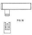
- Proper operation of the system requires that the signal for firing the airbag be transmitted to the airbag gas generator. Towards this end, connectors for airbag gas generators have been developed with a goal of providing a secure and reliable connection for relaying a fire signal to the airbag gas generator during an accident. A typical design for a connector in this field as known in the prior art is depicted in Figure 16 which shows a connector that is retained in the mated position by means of a groove around a male part engaging a rib in the female socket. A drawback of this connection assembly is that it requires the assembly operator to fully push the locking piece into place but gives no indication that full engagement has occurred. It is possible for the operator to fail to fully insert the connector while giving the operator an appearance of locking engagement between the components.
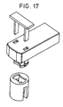
- Manufacturers are now seeking to improve the retention of the connector by employing a means for positively retaining the connector within the catch. An example of a prior art connector employing a positive latching mechanism is shown in Figure 17. The connector of Figure 17 incorporates a separate locking piece having latching legs for insertion into the mated connector. The reliability of this configuration also suffers due to the possibility that an assembly operator may altogether forget to insert the locking piece into the mated connector or may likewise not fully insert the locking piece into a locking position.
- There is therefore a need in the art for an electrical connection assembly for an airbag gas generator assembly that provides a positive latching mechanism with a two-piece connection assembly. The connection assembly should work automatically without requiring additional effort on the part of the assembly operator. Furthermore, it is desirable to provide an electrical connection assembly that tends to force the mating components apart until the fully mated position is reached. It is also desirable to provide an electrical connection assembly that requires a separate tool and two independent releasing forces to attain disconnection. Additionally, it is desirable to provide an electrical connection assembly for an airbag gas generator assembly that utilises a minimum number of parts to ensure reliable assembly of the connector assembly constituent elements.
- United Kingdom Patent Application GB-2063587-A, discloses an electrical cable connector of the snatch type comprising two relatively axially movable parts adapted to be coupled together and uncoupled by a "push-on" and "pull-off' technique. The connector assembly comprises an elongate male connector housing and a dependent housing shaft, and an elongate first electrical contact supported in the housings. The first electrical contact has a first cable terminating end and an opposed interconnection end extending into the shaft. A latch is rotatably supported by the connector housing about the shaft. The connector assembly further includes a female connector housing with a central cavity therein for insertable connection with the housing shaft. The connector assembly also comprises a second electrical contact supported in the cavity of the female connector housing for electrical engagement with the interconnection end of the first contact upon insertable engagement between the housing shaft and the female connector housing. Three equally spaced pins are formed on the female connector housing for matingly receiving the latch of the male connector. The latch is rotatably movable into locking engagement with the pins on the female connector housing under the bias of the pring upon insertable engagement between the shaft and the female connector.
- It is an object of the present invention to provide a positive retention latch feature for an electrical connection assembly for an airbag gas generator assembly.
- It is another object of the present invention to provide an electrical connection assembly employing a split ferrite shield.
- It is still another object of the present invention to provide an electrical connection assembly for an airbag gas generator assembly having an automatic retention latch assembly that requires no additional actions by an assembly operator to positively connect.
- It is a further object of the present invention to provide an electrical connection assembly for an airbag gas generator assembly that requires a single force to positively connect and requires multiple independent simultaneously applied forces to disconnect.
- It is a further object of the present invention to provide an electrical connection assembly for an airbag gas generator assembly that forces the connecting components apart until the fully mated position is reached.
- It is yet another object of the present invention to provide an electrical connection assembly for an airbag gas generator assembly having an automatic positive retention latch feature that requires the application of multiple independent release forces for disconnection.
- In the efficient attainment of these and other objects the present invention provides a connector assembly comprising: a male connector including an elongate male connector housing and a dependent housing shaft; an elongate first electrical contact supported in said housing having a first cable terminating end and an opposed interconnection end extending into said shaft; a latch rotatably supported by said housing about said shaft; a female connector including a female connector housing having a central cavity therein for insertable connection with said housing shaft; a second electrical contact supported in said cavity of said female connector housing for electrical engagement with said interconnection end of said first contact upon insertable engagement between said housing shaft of said male connector and said female connector housing; and a mating latch receiving element formed on said female connector housing for matingly receiving said latch of said male connector; wherein said latch is rotatably movable into locking engagement with said latch receiving element under the bias of a spring upon insertable engagement between said shaft and said female connector housing, and said latch includes engaging means accessible through said housing for rotating said latch against the bias of said spring.
- The connector assembly of an embodiment of the present invention cannot be disconnected by simply pulling the plug connector in a direction opposite to the insertion direction.
- One embodiment of the present invention also provides a split ferrite shield within the body of the connector. Each of the leads of the connector are contiguous with the contacts of the connector shaft through an elongate channel formed between the two ferrite halves.
- An alternate embodiment of the present invention employs a conventional induction coil for shielding the connector.
- The present invention achieves the above-stated objectives utilising a minimum of parts to facilitate the assembly of the connector.
- Figure 1A shows the alignment of the plug connector and socket connector of the present invention.
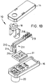
- Figure 1B shows an exploded view of the plug connector of the present invention.
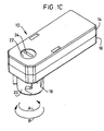
- Figure 1C shows the a isometric view of the plug connector of Figure 1A, showing the relationship between the cover, base, and latch.
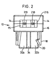
- Figure 2 shows a rear view of the plug connector of Figure 1A.
- Figure 3 shows the underside of the plug connector of Figure 1A, showing the relationship between the plug connector shaft, the plug connector contacts, the keying feature of the plug connector shaft, and the arcuate apertures for the latch prongs.
- Figure 4 is an isometric view of the interior expanse of the cover.
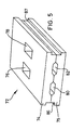
- Figure 5 is an isometric view of the ferrite assembly of the plug connector of the present invention.
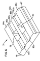
- Figure 6 shows one of the symmetrical halves of the ferrite assembly of Figure 5.
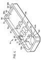
- Figure 7 is an isometric view showing the interior expanse of the base of the plug connector of Figure 1A.
- Figure 8 is a top plan view of the interior expanse of the base of Figure 7.
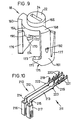
- Figure 9 is an isometric view of the latch of the plug connector of Figure 1A.
- Figure 10 is an isometric view of the contacts supported within the housing of the present invention.
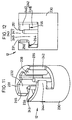
- Figure 11 is an isometric view of the socket connector of Figure 1.
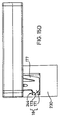
- Figure 12 is a elevational view of the socket connector of Figure 1.
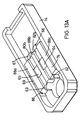
- Figure 13A shows one of the symmetrical halves of the ferrite assembly of Figure 5 inserted in place in the interior expanse of the cover.
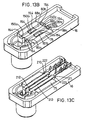
- Figure 13B shows the other symmetrical half of the ferrite assembly of Figure 6 inserted into the interior expanse of the housing of Figure 7.
- Figure 13C shows the contacts of Figure 10 inserted into the assembly of Figure 13B.
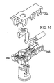
- Figure 13D shows the relative orientation of the assembly of Figure 13C and the latch of Figure 9 prior to inserting the latch therein.
- Figure 13E shows the assembly of Figure 13C with the latch of Figure 9 inserted therein.
- Figure 14 shows a partially exploded view of an alternate embodiment of a plug connector of the present invention.
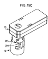
- Figures 15A-D depict the mating of the connector assembly of Figure 1.
- Figure 16 shows an electrical connection assembly of the prior art.
- Figure 17 shows an electrical connection assembly of the prior art employing a separate member to provide positive latching.
- The present invention includes an
electrical connector assembly 1 for providing connection between components of an airbag gas generator assembly. Theconnector assembly 1 comprises amale plug connector 10 and afemale socket connector 12. - With reference to Figure 1B, plug
connector 10 includes an electricallyinsulative housing 15 having a base 16, acover 14, and alatch 18 for providing positive retentive interconnection withsocket connector 12 of Figure 1A.Base 16 includesstationary shaft 20 extending from the underside thereof which has an outer surface that conforms to the interior surface ofsocket connector 12.Plug connector 10 supportselectrical contacts Electrical contacts Contacts cable terminating end socket contact socket connector 12.Housing 15 includes ferrite assembly 72 (shown in full detail in Figure 5) formed of twosymmetrical ferrites electrical contacts Latch 18 is movably supported inhousing 15 with limited freedom to rotate aboutstationary housing shaft 20.Latch 18 includes a pair ofprongs base 16 and provide for locking retention withsocket connector 12. - With additional reference to Figure 12,
socket connector 12 includes an insulativefemale connector housing 230 which supports a pair of contact pins 234, 235 designed for interconnection withcontacts connector 10. As also shown in Figure 11,housing 230 includes a pair of flag-shapedapertures prongs latch 18 whenplug connector 10 is fully mated tosocket connector 12. - As
plug connector 10 is pushed intosocket connector 12, physical contact between the prongs oflatch 18 andtabs apertures socket connector 12 cause theprongs latch 18 to rotate in the direction of arrow A against the urging ofcantilever arms hooks prongs tabs socket connector 12,cantilever arms latch 18 in the direction of arrow B. Decompression of thecantilever arms prongs socket connector 12 to provide positive latching interconnection betweenplug connector 10 andsocket connector 12. - Disconnection of
plug connector 10 fromsocket connector 12 requires that a tool, such as a screwdriver, be inserted intolatch slot 24 and rotated in the direction of arrow A against the urging ofcantilever arms hooks prongs tabs connector 10 may be withdrawn fromsocket connector 12. Connection of the connector assembly therefore only requiresplug connector 10 to be pushed intosocket connector 12 in a single insertion direction. Disconnection of the connector assembly, however, requires, first, a tool to rotatelatch 18 out of engagement withtabs socket connector 12, and second, the withdrawal ofplug connector 10 fromsocket connector 12 in a direction opposite to the insertion direction. - Having provided a general overview of
connector assembly 1 of the present invention, a more detailed description of the components of the preferred embodiment of the present invention follows. - Figure 2 shows a rear view of
plug connector 10. The interface betweencover 14 andbase 16 is seen to define a termination aperture 26 which provides access totermination end contacts upper ferrite 74 andlower ferrite 75.Upper ferrite 74 andlower ferrite 75 provide a shielding function forplug connector 10 so as to prevent false signal generation associated with electromagnetic fields. Figure 2 also shows thelongitudinal ridge 34 which provides a keying function withsocket connector 12 to prevent malassembly of the connector assembly. - Figure 3 is a bottom view of
plug connector 10 and more clearly illustrates keyingsurfaces longitudinal ridge 34 ofhousing shaft 20. The keying function is contemplated to be provided by any of the methods known in the electrical connector art for ensuring assembly of two components in a single orientation.Housing shaft 20 definesshaft expanse 35 in whichfirst socket 214 andsecond socket 215 are supported bybase 16. Disposed along the exterior surface ofshaft 20 can be seenfirst prong aperture 36 andsecond prong aperture 37 through which theprongs latch 18 extend frombase 16. Also visible in Figure 3 is firstlower ferrite clip 46 and secondlower ferrite clip 47 which are disposed within the interior ofplug connector 10 and which are accessible through firstlower clip aperture 48 and secondlower clip aperture 49, respectively. As will be seen later, lower ferrite clips 46 and 47 engage and holdlower ferrite 75 in thebase 16. - Figure 4 shows an internal view of
cover 14.Cover 14 includes acover floor 50 which is parametrically bounded bycover wall 52.Cover wall 52 includes first and second bowedsurfaces latch 18 whenplug connector 10 is assembled.Cover wall 52 terminates incover rim 54.Cover wall 52 definescover expanse 56 or the interior volume ofcover 14.Cover 14 partially defines termination aperture 26 due to the provision of recessedrim 58 spanning betweenupper aperture extents cover 14 includeslatch keyhole 60 which accommodateslatch summit 22 as is shown in Figures 1A and 1B.Latch keyhole 60 is positioned to be concentric with the arcs of rotation through which prongs 160, 161 oflatch 18 deflect. -
Cover expanse 56 includes successive pairs of downstands projecting fromcover floor 50. As viewed from the position of the latch atkeyhole 60, these downstands are seen to be first and second proximal downstand, 62, 63, first and second medial downstand, 64, 65, and first and second distal downstand, 66, 67 respectively. Figure 4 also shows secondupper ferrite clip 69 which projects over second upperferrite clip aperture 71 defined bywall 52 andfloor 50. First upper ferrite clip 68 and first upper ferrite clip aperture 70 are hidden from view in Figure 4 and are located transversely acrosscover expanse 56 oncover wall 52. - Figure 5 shows
ferrite assembly 72 which comprisesupper ferrite 74 andlower ferrite 75 positioned in registry with each other.Ferrite assembly 72 includes firstmedial passage 76 and secondmedial passage 78 extending therethrough.Passages Ferrite assembly 72 also includes firstlead channel 80 and secondlead channel 82 extending longitudinally therethrough. Preferably, longitudinal indentations are formed inupper ferrite 74 andlower ferrite 75 and are placed in registry so as to formchannels - Figure 6 shows
lower ferrite 75. In the preferred embodiment,upper ferrite 74 andlower ferrite 75 are formed to be interchangeable and thereby facilitating the assembly ofconnector 10. As seen in Figure 6,lower ferrite 75 is simply characterized as a ferrite block having a pair of longitudinal grooves formed therein and a pair of through holes formed perpendicularly through the grooves. Eachferrite connector 10. Each ferrite would therefore includeapertures cover 14 or the corresponding first and second medial upstands ofbase 16, shown in Figure 7.Ferrite interface surfaces upper ferrite 74. Leadchannels surfaces 80a-c and 82a-c, respectively. Furthermore,ferrite 75 includes transversely spaced lower clip engagement surfaces 86 and 87 which are engaged bylower clips lower ferrite 75 within thebase 16.Surfaces cover 14. - Figure 7 and 8 depict the
base 16 of the present invention.Base 16 includesbase floor 100 which is parametrically bounded bybase wall 102.Base wall 102 includes first and second bowedsurfaces latch 18 thereadjacent.Base wall 102 terminates inbase rim 104 to thereby definebase expanse 106. As is seen,base wall 102 also includes recessedrim 108 spanning betweenlower aperture extents ferrite clip apertures base wall 102. - Towards the opposing longitudinal end of
base 16,base floor 100 definesfirst prong aperture 36 andsecond prong aperture 37.First prong aperture 36 is defined adjacent to first bowedsurface 103a ofbase wall 102 andconvex rail surface 124.Latch rail 120 projects upward frombase floor 100adjacent prong apertures Latch rail 120 includesconcave rail surface 122 and aconvex rail surface 124 extending between firstproximal upstand 112 and secondproximal upstand 113. Similarly, thesecond prong aperture 37 is defined between the second bowedsurface 103b andconvex rail surface 124.Latch rail 120 terminates at arail rim surface 126 which supports latch 18 thereon.Rail 120 also definesrail notch 130 adjacent recessedrail rim 128. The firstcantilevered spring stop 132 and the secondcantilevered spring stop 134 project radially outward fromlatch rail 120adjacent latch apertures Concave rail surface 122 definescontact expanse 123 and communicates withfirst socket aperture 144 andsecond socket aperture 146 defined bybase floor 100. - From the perspective of
contact expanse 123 can seen successive pairs of upstands projecting frombase floor 100 and include first and secondproximal upstands medial upstands distal upstands distal upstands contact strut support distal upstands contact strut support first socket aperture 144 and termination aperture 26 of the assembledplug connector 10. Likewise, the second contract strut supports 151a-c are positioned between thesecond socket aperture 146 and termination aperture 26 of the assembledconnector 10.Socket aperture 144 is also defined bysocket rim 145.Socket aperture 146 is likewise partially defined bysocket rim 147. Figure 8 more clearly shows the projection of first and second lower ferrite clips 46, 47 intobase expanse 106 and the relation to first andsecond clip apertures base floor 100 andbase wall 102. - Figure 9 shows latch 18 of the present invention. In its preferred embodiment, latch 18 includes first and second latch prongs 160 and 161 positioned at opposing ends of
latch brim 164.Latch brim 164 is seen to extend proximately halfway around the cylindrical outer surface oflatch drum 166. Latch prongs 160, 161 are positioned in flush end relationship with the opposing ends oflatch brim 164. Latch prongs 160,161 are also positioned in flush edge relationship withlatch brim 164 to definelatch shoulder 168.Latch drum 166 is formed to have a diameter to allow it to extend throughkeyhole aperture 60 ofcover 14 to thereby makinglatch slot 24 accessible throughcover 14. -
Latch tooth 190 depends fromlatch brim 164 and has an circumferential shape in conformance withbrim 164. In the assembled condition,latch tooth 190 will be disposed innotch 130 oflatch rail 120 and prevent over-rotation oflatch 18. Eachlatch prong latch hook cantilever spring arm hook hook respective hookface opposed tapering undersurface spring arm - Figure 10 shows
first contact 210 andsecond contact 211 to be contained withinconnector 10. Contact 210 and contact 211 are preferably identically proportioned so as to enhance commonality during manufacture. It can been thatcontacts elongate contact strut socket contact contact flange socket contact socket connector 12 as is shown in Figure 1A. Furthermore, eachtermination end teeth termination end connector 12 is to be mated. For example, a standard crimp design could be employed for connecting to conventional round stranded wire, whereas an insulation displacement termination such as is shown in Figure 14 could also be employed for round wire. - Figures 11 and 12
shows socket connector 12 in detail. Generally,socket connector 12 includes afemale connector housing 230 having anopen end 231 and defining acavity 232.Housing 230 supports first and second electrical contact pins 234, 235 which extend intocavity 232 and which matingly electrically engage first andsecond socket contacts housing shaft 20.Female connector housing 230 includes aninternal cavity wall 238 having a shape conforming to the exterior surface ofhousing shaft 20. Contact pins 234, 235 are in electrical contiguity with other circuit components. -
Female connector housing 230 defines first and second flag-shapedapertures second prongs latch 18. Each flag-shaped aperture includes atab first portion 246, 247 of flag-shapedaperture open end 231 and having a smaller circumferential expanse than a second portion 248, 249 of flag-shapedaperture open end 231 offemale connector housing 230.Tabs prong deflection element undersurface latch prong housing shaft 20 intohousing 230. Eachtab hookface surface hookface surface prong connector housing 15 has been fully mated withfemale connection housing 230 and each prong has been deflected into the locked position. - Figures 13A-F depict a sequence for assembling
plug connector 10 of the present invention. In Figure 13Aupper ferrite 74 is positioned withincover 14. First and secondmedial downstands apertures upper ferrite 74. Note that the exposed faces ofproximal downstands medial downstands distal downstands interface surfaces 88a-c and channel surfaces 80b and 82b. Furthermore,clip 69 is shown to extend out overclip engagement surface 86. Due to the elastomeric characteristics ofcover 14,upper ferrite 74 may be pushed past upper ferrite clips 68, 69 so thatferrite 74 snaps into place withincover 14. Similarly, Figure 13B showsferrite 75 assembled withinbase 16. As is seen in Figure 13B, firststrut support surfaces 150a-c and secondstrut support surfaces 151a-c rise abovechannels interface surfaces 88a-c offerrite 75. However, here it is seen that each of the upstands includeslongitudinal tabs 154 extending above the plane ofinterface surface 88a-c. Theselongitudinal tabs 154 extend only so far above interface surface 88 so as to come into contact with the respective downstands ofcover 14 while still allowing interface surfaces 88a-c ofupper ferrite 74 andlower ferrite 75 to come into engagement as well. - Figure 13C shows each
contact base 16. Eachelongate strut respective strut support 150a-c, 151a-c so as to be suspended aboveferrite 75. Whenupper ferrite 74 is placed in registry abovelower ferrite 75, eachstrut upper ferrite 74 so as to prevent the possibility of short circuiting the contacts across the ferrite.Flanges distal upstands ferrite 72. Furthermore,socket contacts respective socket apertures pins socket connector 12. - Figure 13D shows
latch 18 just prior to its insertion intobase 16. Latch prongs 160 and 161 will be inserted throughlatch apertures latch detent 192 which provides a taperingsurface 194 as its being inserting intobase 16 and aflat abutment surface 196 which interfaces withbase 16 so as to prevent the easy withdrawal oflatch 18 back out frombase 16.Latch 18 is positioned so thatlatch brim 164 sits atoprail rim surface 126 andlatch tooth 190 is disposed withinrail notch 130. Oncelatch 18 is inserted intobase 16 as shown in Figure 13E, latch 18 will have limited freedom for arcuate movement abouthousing shaft 20. The movement oflatch 18 will be limited by a combination of the amount of travel providedtooth 190 innotch 130 and by the deflection ofcantilevered spring arms Cover 14, includingupper ferrite 74, may then be positioned over the assembly shown in Figure 13E as is shown in Figure 1A. - Figure 14 shows an alternate embodiment of the present invention where the shielding of
contacts wound wire coil 260. Wound wire coils are known in the art for their shielding capabilities. Figure 14 also illustrates one possible means for attachingcover 14 tobase 16 by providingdeflectable clips 264 which may be inserted overbulges 266 whencover 14 is placed onbase 16. It is contemplated by the present invention that cover 14 may be attached or adhered to base 16 by any means known in the art for joining two components together. - Other particular embodiments are contemplated to fall within the scope of the present invention. For example, either pins or connectors may be mounted in either plug
connector 10 orsocket connector 12 or both so long as they provide mating electrical connection with the other component of the connector assembly of the present invention. Additionally, whileprongs shaft expanse 35, it is also contemplated by the present invention that the prongs may extend throughexpanse 35 and engage afemale connector housing 230 that is insertably connected withinshaft expanse 35. Such an embodiment provides a tamper-proof connection betweenhousing 15 andsocket connector 12 asprongs latch slot 24 throughcover 14. - Having provided a detailed description of possible embodiments of the present invention, a more detailed description of the operation of
connector assembly 10 follows. Asplug connector 10 is brought down uponsocket connector 12, as shown in Figures 15A-C, taperingundersurface latch hook prong engagement member tab Housing shaft 20 is keyed to engagesocket connector 12 in a single mating orientation. Continued insertion ofplug connector 10 intosocket connector 12 results inmember latch hook undersurface latch 18 to rotate abouthousing shaft 20 in the latch deflection direction represented by arrow A. Rotation oflatch 18 in the direction of arrow A causes the deflection ofcantilever arm latch hook tab cantilever arm latch 18 to move in the direction of arrowB causing hookface socket connector hookface 254 which defines a connected and locked position betweenplug connector 10 andsocket connector 12.Plug connector 10 is thereby positively retained withinsocket connector 12 due to the interfering engagement between the hookfaces of the latch and the socket connector. - As can be seen in Figure 1B, latch 18 includes
latch summit 22 which is accessible throughcover 14.Latch summit 22 defineslatch slot 24 which may be engaged by a tool such as a screwdriver, not shown, and turned in the deflection direction of arrow A so as to deflectcantilever spring arm latch hook plug connector 10 and withdraw it away fromsocket connector 12 to achieve disconnection. - While the particular embodiment of the present invention has been shown and described, it will be obvious to those skilled in the art that changes and modifications may be made without departing from the teachings of the invention. The matter set forth in the foregoing description and accompanying drawings is offered by way of illustration only and not as a limitation. The actual scope of the invention is intended to be defined in the following claims when viewed in their proper perspective based on the prior art.
Claims (9)
- A connector assembly comprising:wherein said latch (18) is rotatably movable into locking engagement with said latch receiving element (242) under the bias of a spring (176) upon insertable engagement between said shaft (20) and said female connector housing (230), anda male connector (10) including an elongate male connector housing (15) and a dependent housing shaft (20);an elongate first electrical contact (210) supported in said housing (15) having a first cable terminating end (218) and an opposed interconnection end (214) extending into said shaft (20);a latch (18) rotatably supported by said housing (15) about said shaft (20);a female connector (12) including a female connector housing (230) having a central cavity (232) therein for insertable connection with said housing shaft (20); a second electrical contact (234) supported in said cavity (232) of said female connector housing (230) for electrical engagement with said interconnection end (214) of said first contact (210) upon insertable engagement between said housing shaft (20) of said male connector (10) and said female connector housing (230); anda mating latch receiving element formed on said female connector housing (230) for matingly receiving said latch (18) of said male connector (10);
said latch (18) includes engaging means (24) accessible through said housing (15) for rotating said latch (18) against the bias of said spring (176). - A connector assembly of claim 1, wherein said latch (18) receiving element comprises a pair of flag-shaped apertures (242, 243), said female connector housing (230) including a tab (244, 245) extending into each flag-shaped aperture (242, 243), said tab (244, 245) being in flush end relationship with said female connector housing (230).
- A connector assembly of claim 2, wherein said latch (18) includes a pair of elongate prongs (160, 161) depending from said male connector housing (15), wherein each of said prongs (160, 161) includes:a locking surface (172, 173) for opposing the underside of said tab (244, 245) when said shaft (20) is mated with said female connector housing (230); anda tapering underside (174, 175) from the free end of said latch (18) to said locking surface (172, 173).
- A connector assembly of any one of claims 1 to 3, wherein said elongate contact (210) is shielded within said housing (15) to prevent unintentional signal generation by exposure of the connector assembly to an electromagnetic field.
- A connector assembly of claim 4, wherein the shielding is provided by a ferrite assembly (72), wherein said elongate electrical contact (210) is supported in spaced isolation through said ferrite assembly (72).
- A connector assembly of claim 5, wherein said ferrite assembly (72) comprises a top ferrite component (74) and a bottom ferrite component (75), said top ferrite component (74) being secured in the housing cover (14) and said bottom ferrite component (75) being secured in the housing base (16).
- A connector assembly of claim 4, wherein said contact (210) includes a wound wire induction coil (260) within said male connector housing (15).
- A connector assembly of any one of claims 1 to 7, wherein said connector shaft (20) and said female connector housing (230) are shaped to provide keying means to prevent malassembly of said shaft (20) to said female connector housing (230).
- A connector assembly of any one of claims 1 to 8, wherein said latch (18) includes a cantilever spring (176), wherein the free end of said cantilever spring (176) engages said male connector housing (15).
Applications Claiming Priority (2)
| Application Number | Priority Date | Filing Date | Title |
|---|---|---|---|
| US1829096P | 1996-05-24 | 1996-05-24 | |
| US18290P | 1996-05-24 |
Publications (3)
| Publication Number | Publication Date |
|---|---|
| EP0808749A2 EP0808749A2 (en) | 1997-11-26 |
| EP0808749A3 EP0808749A3 (en) | 1999-11-03 |
| EP0808749B1 true EP0808749B1 (en) | 2003-03-12 |
Family
ID=21787194
Family Applications (1)
| Application Number | Title | Priority Date | Filing Date |
|---|---|---|---|
| EP97303558A Expired - Lifetime EP0808749B1 (en) | 1996-05-24 | 1997-05-23 | Connector for airbag gas generator |
Country Status (5)
| Country | Link |
|---|---|
| US (1) | US5895282A (en) |
| EP (1) | EP0808749B1 (en) |
| JP (1) | JP3451180B2 (en) |
| CA (1) | CA2205742C (en) |
| DE (1) | DE69719598T2 (en) |
Families Citing this family (37)
| Publication number | Priority date | Publication date | Assignee | Title |
|---|---|---|---|---|
| EP0999952B1 (en) | 1997-07-31 | 2002-01-09 | The Whitaker Corporation | Squib connector |
| US6131947A (en) * | 1998-01-23 | 2000-10-17 | Trw Inc. | Electrical connector for air bag inflator |
| ATE363749T1 (en) | 1998-07-15 | 2007-06-15 | Thomas & Betts Int | CONNECTOR FOR AIRBAG GAS GENERATOR |
| US6234843B1 (en) * | 1998-12-07 | 2001-05-22 | Framatome Connectors Interlock Inc. | Low profile filter connector with ferrite |
| DE19935969C2 (en) * | 1999-07-30 | 2001-12-13 | Framatome Connectors Int | Short-circuit contact carrier for fuse base |
| JP3508016B2 (en) * | 1999-12-24 | 2004-03-22 | 住友電装株式会社 | connector |
| KR100564091B1 (en) * | 2000-03-01 | 2006-03-27 | 니혼 앗사쿠단시세이조 가부시키가이샤 | Electrical connection system |
| DE10025295C2 (en) * | 2000-05-22 | 2002-10-31 | Fci Automotive Deutschland Gmb | Connectors, in particular for airbag ignition systems |
| US6390845B1 (en) * | 2001-01-10 | 2002-05-21 | M/A-Com Private Radio Systems, Inc. | Electrical connector for a portable radio |
| JP2003249308A (en) * | 2002-02-25 | 2003-09-05 | Tyco Electronics Amp Kk | Electrical connector assembly |
| US6799983B2 (en) | 2002-06-28 | 2004-10-05 | Amphenol-Tuchel Electronics Gmbh | Electrical connector with static discharge feature |
| WO2004004071A2 (en) * | 2002-06-28 | 2004-01-08 | Amphenol-Tuchel Electronics Gmbh | Electrical connector |
| US6837732B2 (en) * | 2002-06-28 | 2005-01-04 | Amphenol-Tuchel Electronics Gmbh | Filtered electrical connector with ferrite block combinations and filter assembly therefor |
| US6767240B2 (en) * | 2002-06-28 | 2004-07-27 | Amphenol-Tuchel Electronics Gmbh | Electrical connector with cable insulation strain relief feature |
| US20040192098A1 (en) * | 2002-06-28 | 2004-09-30 | Slobodan Pavlovic | Electrical connector with spring back/self rejection feature |
| US6705886B1 (en) * | 2003-01-23 | 2004-03-16 | Fci Americas Technology, Inc. | Electrical connector having connector position assurance member |
| US6811424B2 (en) * | 2003-03-26 | 2004-11-02 | Fci Americas Technology, Inc. | Electrical connector having connector position assurance member |
| US6921279B2 (en) * | 2003-06-05 | 2005-07-26 | Fci Americas Technology, Inc. | Electrical connector with connector position assurance member |
| US6857892B2 (en) * | 2003-06-05 | 2005-02-22 | Fci Americas Technology, Inc. | Electrical connector with connector position assurance member |
| US6964579B2 (en) * | 2003-06-06 | 2005-11-15 | Fci Americas Technology, Inc. | Position assured connector |
| DE102004008712A1 (en) * | 2004-02-23 | 2005-09-08 | Tyco Electronics Amp Gmbh | plug |
| DE102004020933B3 (en) * | 2004-04-28 | 2005-12-29 | Tyco Electronics Amp Gmbh | Plug, in particular Zündpillenstecker |
| DE102005021375B4 (en) * | 2005-05-04 | 2007-02-01 | Yazaki Europe Ltd., Hemel Hempstead | Connectors, in particular for airbag ignition systems |
| JP4558619B2 (en) * | 2005-09-30 | 2010-10-06 | 矢崎総業株式会社 | connector |
| US8425254B2 (en) * | 2007-03-19 | 2013-04-23 | Fci Automotive Holding | Electrical connector with ferrite block assembly |
| US7354310B1 (en) * | 2007-06-07 | 2008-04-08 | Fci Americas Technology, Inc. | Electrical connector housing cover |
| JP5751194B2 (en) * | 2011-09-08 | 2015-07-22 | 日立金属株式会社 | Connector and wire harness |
| JP6177337B2 (en) * | 2012-11-12 | 2017-08-09 | デルフィ・インターナショナル・オペレーションズ・ルクセンブルク・エス・アー・エール・エル | Connector assembly with automatic secondary lock |
| JP2014110182A (en) * | 2012-12-03 | 2014-06-12 | Jst Mfg Co Ltd | Electric connector, and connection device of squib |
| JP6537819B2 (en) | 2014-12-18 | 2019-07-03 | 日本航空電子工業株式会社 | Connector pair |
| USD772231S1 (en) * | 2015-04-16 | 2016-11-22 | Physical Optics Corporation | Universal integrative mission module interface |
| JP6593631B2 (en) * | 2015-09-24 | 2019-10-23 | 株式会社オートネットワーク技術研究所 | connector |
| KR102633071B1 (en) * | 2016-12-27 | 2024-02-05 | 한국단자공업 주식회사 | Bulb holder |
| EP3396785B1 (en) * | 2017-04-27 | 2020-12-09 | Aptiv Technologies Limited | Connector assembly |
| US10276948B1 (en) | 2018-06-13 | 2019-04-30 | Denso International America, Inc. | Battery connector for generator |
| IT201900002621A1 (en) * | 2019-02-22 | 2019-05-22 | Valentini S R L | Electrical connection devices comprising contact means for controlling an auxiliary circuit |
| CN112260001A (en) * | 2020-10-19 | 2021-01-22 | 温州市乐伊汽车配件有限公司 | Automobile connection plug terminal with high reliability |
Family Cites Families (17)
| Publication number | Priority date | Publication date | Assignee | Title |
|---|---|---|---|---|
| US3869191A (en) * | 1973-10-11 | 1975-03-04 | Gen Motors Corp | Connector means having shorting clip |
| GB2063587B (en) * | 1979-11-16 | 1983-12-14 | Electronic Components Ltd | Snatch-type electrical connectors |
| US4380346A (en) * | 1981-04-24 | 1983-04-19 | Thiokol Corporation | Method of and apparatus for speeding the response of an air bag inflator at low temperatures |
| US4850888A (en) * | 1988-04-22 | 1989-07-25 | Amp Incorporated | Electrical connector with a deflectable shunt |
| JP2571310B2 (en) * | 1990-12-14 | 1997-01-16 | 矢崎総業株式会社 | Connector lock security mechanism |
| DE4140692A1 (en) * | 1991-12-10 | 1993-06-17 | Trw Repa Gmbh | ELECTRICAL CONNECTING TO A PYROTECHNICAL GAS GENERATOR PROVIDED WITH ELECTRICAL IGNITION |
| US5275575A (en) * | 1992-10-09 | 1994-01-04 | Trw Inc. | Electrical connection system with safety interlock |
| GB9305758D0 (en) * | 1993-03-19 | 1993-05-05 | Amp Gmbh | Electrical connector having short circuiting facility |
| US5297976A (en) * | 1993-05-17 | 1994-03-29 | Electro-Wire Products, Inc. | Sealable electrical connector for an airbag sensor |
| US5401180A (en) * | 1993-06-01 | 1995-03-28 | Itt Corporation | Connector shorting spring |
| JPH0778657A (en) * | 1993-09-07 | 1995-03-20 | Fujitsu Ltd | Mounting structure for EMI prevention filter |
| EP0650229A3 (en) * | 1993-10-22 | 1997-01-02 | Amphenol Tuchel Elect | Airbag safety system. |
| US5498164A (en) * | 1994-05-09 | 1996-03-12 | Ward; Mark C. | Automotive steering column electrical connector |
| US5528161A (en) * | 1994-09-15 | 1996-06-18 | Venturedyne Limited | Through-port load carrier and related test apparatus |
| US5458371A (en) * | 1994-10-27 | 1995-10-17 | Morton International, Inc. | Crimp-formed joint housings for air bag inflators |
| US5616045A (en) * | 1995-07-14 | 1997-04-01 | Augat Inc. | Squib connector for automotive air bag assembly |
| DE29514740U1 (en) * | 1995-09-15 | 1995-11-16 | Amphenol-Tuchel Electronics Gmbh, 74080 Heilbronn | Electrical connector |
-
1997
- 1997-05-19 US US08/858,720 patent/US5895282A/en not_active Expired - Fee Related
- 1997-05-21 CA CA002205742A patent/CA2205742C/en not_active Expired - Fee Related
- 1997-05-23 EP EP97303558A patent/EP0808749B1/en not_active Expired - Lifetime
- 1997-05-23 DE DE69719598T patent/DE69719598T2/en not_active Expired - Lifetime
- 1997-05-26 JP JP13528697A patent/JP3451180B2/en not_active Expired - Lifetime
Also Published As
| Publication number | Publication date |
|---|---|
| JP3451180B2 (en) | 2003-09-29 |
| DE69719598D1 (en) | 2003-04-17 |
| US5895282A (en) | 1999-04-20 |
| EP0808749A2 (en) | 1997-11-26 |
| CA2205742C (en) | 2004-08-17 |
| DE69719598T2 (en) | 2003-12-11 |
| EP0808749A3 (en) | 1999-11-03 |
| JPH1092517A (en) | 1998-04-10 |
| CA2205742A1 (en) | 1997-11-24 |
Similar Documents
| Publication | Publication Date | Title |
|---|---|---|
| EP0808749B1 (en) | Connector for airbag gas generator | |
| EP0869883B1 (en) | Orientationless squib connector assembly for automotive air bag assemblies | |
| US6663411B2 (en) | Clamshell connector for airbag gas generator | |
| US6435894B2 (en) | Connector for airbag gas generator | |
| KR100282328B1 (en) | Electrical connection system with interlock | |
| JP2647336B2 (en) | Electrical connection device | |
| EP1150389B1 (en) | Clamshell connector for airbag gas generator | |
| US6276953B1 (en) | Orientationless squib connector assembly for automotive air bag assemblies | |
| JP3165909B2 (en) | Electrical plug connector | |
| JP2887396B2 (en) | Latch mechanism for electrical connector | |
| KR20010087233A (en) | Electrical connection system | |
| US5910028A (en) | Connector | |
| US20090098758A1 (en) | Connection system and squib connector therefor | |
| EP1378973B1 (en) | Orientationless squib connector assembly for automotive air bag assemblies | |
| EP4145645B1 (en) | Electrical connector and methods | |
| MXPA98002792A (en) | Orientationless squib connector assembly for automotive air bag assemblies |
Legal Events
| Date | Code | Title | Description |
|---|---|---|---|
| PUAI | Public reference made under article 153(3) epc to a published international application that has entered the european phase |
Free format text: ORIGINAL CODE: 0009012 |
|
| AK | Designated contracting states |
Kind code of ref document: A2 Designated state(s): BE CH DE ES FR GB IT LI LU NL SE |
|
| PUAL | Search report despatched |
Free format text: ORIGINAL CODE: 0009013 |
|
| AK | Designated contracting states |
Kind code of ref document: A3 Designated state(s): BE CH DE ES FR GB IT LI LU NL SE |
|
| RIC1 | Information provided on ipc code assigned before grant |
Free format text: 6B 60R 16/02 A, 6H 01R 13/62 B, 6H 01R 13/625 B, 6H 01R 13/719 B |
|
| 17P | Request for examination filed |
Effective date: 20000420 |
|
| 17Q | First examination report despatched |
Effective date: 20011228 |
|
| GRAG | Despatch of communication of intention to grant |
Free format text: ORIGINAL CODE: EPIDOS AGRA |
|
| GRAH | Despatch of communication of intention to grant a patent |
Free format text: ORIGINAL CODE: EPIDOS IGRA |
|
| RAP1 | Party data changed (applicant data changed or rights of an application transferred) |
Owner name: THOMAS & BETTS CORPORATION |
|
| GRAH | Despatch of communication of intention to grant a patent |
Free format text: ORIGINAL CODE: EPIDOS IGRA |
|
| GRAG | Despatch of communication of intention to grant |
Free format text: ORIGINAL CODE: EPIDOS AGRA |
|
| GRAA | (expected) grant |
Free format text: ORIGINAL CODE: 0009210 |
|
| AK | Designated contracting states |
Designated state(s): BE CH DE ES FR GB IT LI LU NL SE |
|
| PG25 | Lapsed in a contracting state [announced via postgrant information from national office to epo] |
Ref country code: NL Free format text: LAPSE BECAUSE OF FAILURE TO SUBMIT A TRANSLATION OF THE DESCRIPTION OR TO PAY THE FEE WITHIN THE PRESCRIBED TIME-LIMIT Effective date: 20030312 Ref country code: LI Free format text: LAPSE BECAUSE OF FAILURE TO SUBMIT A TRANSLATION OF THE DESCRIPTION OR TO PAY THE FEE WITHIN THE PRESCRIBED TIME-LIMIT Effective date: 20030312 Ref country code: CH Free format text: LAPSE BECAUSE OF FAILURE TO SUBMIT A TRANSLATION OF THE DESCRIPTION OR TO PAY THE FEE WITHIN THE PRESCRIBED TIME-LIMIT Effective date: 20030312 Ref country code: BE Free format text: LAPSE BECAUSE OF FAILURE TO SUBMIT A TRANSLATION OF THE DESCRIPTION OR TO PAY THE FEE WITHIN THE PRESCRIBED TIME-LIMIT Effective date: 20030312 |
|
| REG | Reference to a national code |
Ref country code: GB Ref legal event code: FG4D |
|
| REG | Reference to a national code |
Ref country code: CH Ref legal event code: EP |
|
| REF | Corresponds to: |
Ref document number: 69719598 Country of ref document: DE Date of ref document: 20030417 Kind code of ref document: P |
|
| PG25 | Lapsed in a contracting state [announced via postgrant information from national office to epo] |
Ref country code: LU Free format text: LAPSE BECAUSE OF NON-PAYMENT OF DUE FEES Effective date: 20030523 |
|
| PG25 | Lapsed in a contracting state [announced via postgrant information from national office to epo] |
Ref country code: SE Free format text: LAPSE BECAUSE OF FAILURE TO SUBMIT A TRANSLATION OF THE DESCRIPTION OR TO PAY THE FEE WITHIN THE PRESCRIBED TIME-LIMIT Effective date: 20030612 |
|
| NLV1 | Nl: lapsed or annulled due to failure to fulfill the requirements of art. 29p and 29m of the patents act | ||
| REG | Reference to a national code |
Ref country code: CH Ref legal event code: PL |
|
| PG25 | Lapsed in a contracting state [announced via postgrant information from national office to epo] |
Ref country code: ES Free format text: LAPSE BECAUSE OF FAILURE TO SUBMIT A TRANSLATION OF THE DESCRIPTION OR TO PAY THE FEE WITHIN THE PRESCRIBED TIME-LIMIT Effective date: 20030930 |
|
| ET | Fr: translation filed | ||
| PLBE | No opposition filed within time limit |
Free format text: ORIGINAL CODE: 0009261 |
|
| STAA | Information on the status of an ep patent application or granted ep patent |
Free format text: STATUS: NO OPPOSITION FILED WITHIN TIME LIMIT |
|
| 26N | No opposition filed |
Effective date: 20031215 |
|
| PGFP | Annual fee paid to national office [announced via postgrant information from national office to epo] |
Ref country code: FR Payment date: 20100601 Year of fee payment: 14 |
|
| PGFP | Annual fee paid to national office [announced via postgrant information from national office to epo] |
Ref country code: IT Payment date: 20100526 Year of fee payment: 14 Ref country code: DE Payment date: 20100527 Year of fee payment: 14 |
|
| PGFP | Annual fee paid to national office [announced via postgrant information from national office to epo] |
Ref country code: GB Payment date: 20100525 Year of fee payment: 14 |
|
| REG | Reference to a national code |
Ref country code: DE Ref legal event code: R119 Ref document number: 69719598 Country of ref document: DE |
|
| REG | Reference to a national code |
Ref country code: DE Ref legal event code: R119 Ref document number: 69719598 Country of ref document: DE |
|
| GBPC | Gb: european patent ceased through non-payment of renewal fee |
Effective date: 20110523 |
|
| REG | Reference to a national code |
Ref country code: FR Ref legal event code: ST Effective date: 20120131 |
|
| PG25 | Lapsed in a contracting state [announced via postgrant information from national office to epo] |
Ref country code: IT Free format text: LAPSE BECAUSE OF NON-PAYMENT OF DUE FEES Effective date: 20110523 |
|
| PG25 | Lapsed in a contracting state [announced via postgrant information from national office to epo] |
Ref country code: FR Free format text: LAPSE BECAUSE OF NON-PAYMENT OF DUE FEES Effective date: 20110531 |
|
| PG25 | Lapsed in a contracting state [announced via postgrant information from national office to epo] |
Ref country code: GB Free format text: LAPSE BECAUSE OF NON-PAYMENT OF DUE FEES Effective date: 20110523 |
|
| PG25 | Lapsed in a contracting state [announced via postgrant information from national office to epo] |
Ref country code: DE Free format text: LAPSE BECAUSE OF NON-PAYMENT OF DUE FEES Effective date: 20111130 |