EP0808734A2 - Sprung- and unsprung-structure relative-velocity computing apparatus for vehicule - Google Patents
Sprung- and unsprung-structure relative-velocity computing apparatus for vehicule Download PDFInfo
- Publication number
- EP0808734A2 EP0808734A2 EP97401117A EP97401117A EP0808734A2 EP 0808734 A2 EP0808734 A2 EP 0808734A2 EP 97401117 A EP97401117 A EP 97401117A EP 97401117 A EP97401117 A EP 97401117A EP 0808734 A2 EP0808734 A2 EP 0808734A2
- Authority
- EP
- European Patent Office
- Prior art keywords
- sprung
- acceleration
- damping
- velocity
- computing
- Prior art date
- Legal status (The legal status is an assumption and is not a legal conclusion. Google has not performed a legal analysis and makes no representation as to the accuracy of the status listed.)
- Granted
Links
Images


Classifications
-
- B—PERFORMING OPERATIONS; TRANSPORTING
- B60—VEHICLES IN GENERAL
- B60G—VEHICLE SUSPENSION ARRANGEMENTS
- B60G17/00—Resilient suspensions having means for adjusting the spring or vibration-damper characteristics, for regulating the distance between a supporting surface and a sprung part of vehicle or for locking suspension during use to meet varying vehicular or surface conditions, e.g. due to speed or load
- B60G17/015—Resilient suspensions having means for adjusting the spring or vibration-damper characteristics, for regulating the distance between a supporting surface and a sprung part of vehicle or for locking suspension during use to meet varying vehicular or surface conditions, e.g. due to speed or load the regulating means comprising electric or electronic elements
- B60G17/016—Resilient suspensions having means for adjusting the spring or vibration-damper characteristics, for regulating the distance between a supporting surface and a sprung part of vehicle or for locking suspension during use to meet varying vehicular or surface conditions, e.g. due to speed or load the regulating means comprising electric or electronic elements characterised by their responsiveness, when the vehicle is travelling, to specific motion, a specific condition, or driver input
- B60G17/0165—Resilient suspensions having means for adjusting the spring or vibration-damper characteristics, for regulating the distance between a supporting surface and a sprung part of vehicle or for locking suspension during use to meet varying vehicular or surface conditions, e.g. due to speed or load the regulating means comprising electric or electronic elements characterised by their responsiveness, when the vehicle is travelling, to specific motion, a specific condition, or driver input to an external condition, e.g. rough road surface, side wind
-
- B—PERFORMING OPERATIONS; TRANSPORTING
- B60—VEHICLES IN GENERAL
- B60G—VEHICLE SUSPENSION ARRANGEMENTS
- B60G17/00—Resilient suspensions having means for adjusting the spring or vibration-damper characteristics, for regulating the distance between a supporting surface and a sprung part of vehicle or for locking suspension during use to meet varying vehicular or surface conditions, e.g. due to speed or load
- B60G17/015—Resilient suspensions having means for adjusting the spring or vibration-damper characteristics, for regulating the distance between a supporting surface and a sprung part of vehicle or for locking suspension during use to meet varying vehicular or surface conditions, e.g. due to speed or load the regulating means comprising electric or electronic elements
- B60G17/018—Resilient suspensions having means for adjusting the spring or vibration-damper characteristics, for regulating the distance between a supporting surface and a sprung part of vehicle or for locking suspension during use to meet varying vehicular or surface conditions, e.g. due to speed or load the regulating means comprising electric or electronic elements characterised by the use of a specific signal treatment or control method
- B60G17/0182—Resilient suspensions having means for adjusting the spring or vibration-damper characteristics, for regulating the distance between a supporting surface and a sprung part of vehicle or for locking suspension during use to meet varying vehicular or surface conditions, e.g. due to speed or load the regulating means comprising electric or electronic elements characterised by the use of a specific signal treatment or control method involving parameter estimation, e.g. observer, Kalman filter
-
- B—PERFORMING OPERATIONS; TRANSPORTING
- B60—VEHICLES IN GENERAL
- B60G—VEHICLE SUSPENSION ARRANGEMENTS
- B60G17/00—Resilient suspensions having means for adjusting the spring or vibration-damper characteristics, for regulating the distance between a supporting surface and a sprung part of vehicle or for locking suspension during use to meet varying vehicular or surface conditions, e.g. due to speed or load
- B60G17/015—Resilient suspensions having means for adjusting the spring or vibration-damper characteristics, for regulating the distance between a supporting surface and a sprung part of vehicle or for locking suspension during use to meet varying vehicular or surface conditions, e.g. due to speed or load the regulating means comprising electric or electronic elements
- B60G17/019—Resilient suspensions having means for adjusting the spring or vibration-damper characteristics, for regulating the distance between a supporting surface and a sprung part of vehicle or for locking suspension during use to meet varying vehicular or surface conditions, e.g. due to speed or load the regulating means comprising electric or electronic elements characterised by the type of sensor or the arrangement thereof
- B60G17/01933—Velocity, e.g. relative velocity-displacement sensors
-
- B—PERFORMING OPERATIONS; TRANSPORTING
- B60—VEHICLES IN GENERAL
- B60G—VEHICLE SUSPENSION ARRANGEMENTS
- B60G17/00—Resilient suspensions having means for adjusting the spring or vibration-damper characteristics, for regulating the distance between a supporting surface and a sprung part of vehicle or for locking suspension during use to meet varying vehicular or surface conditions, e.g. due to speed or load
- B60G17/06—Characteristics of dampers, e.g. mechanical dampers
- B60G17/08—Characteristics of fluid dampers
-
- B—PERFORMING OPERATIONS; TRANSPORTING
- B60—VEHICLES IN GENERAL
- B60G—VEHICLE SUSPENSION ARRANGEMENTS
- B60G2400/00—Indexing codes relating to detected, measured or calculated conditions or factors
- B60G2400/10—Acceleration; Deceleration
- B60G2400/102—Acceleration; Deceleration vertical
-
- B—PERFORMING OPERATIONS; TRANSPORTING
- B60—VEHICLES IN GENERAL
- B60G—VEHICLE SUSPENSION ARRANGEMENTS
- B60G2400/00—Indexing codes relating to detected, measured or calculated conditions or factors
- B60G2400/20—Speed
- B60G2400/202—Piston speed; Relative velocity between vehicle body and wheel
-
- B—PERFORMING OPERATIONS; TRANSPORTING
- B60—VEHICLES IN GENERAL
- B60G—VEHICLE SUSPENSION ARRANGEMENTS
- B60G2400/00—Indexing codes relating to detected, measured or calculated conditions or factors
- B60G2400/20—Speed
- B60G2400/206—Body oscillation speed; Body vibration frequency
-
- B—PERFORMING OPERATIONS; TRANSPORTING
- B60—VEHICLES IN GENERAL
- B60G—VEHICLE SUSPENSION ARRANGEMENTS
- B60G2400/00—Indexing codes relating to detected, measured or calculated conditions or factors
- B60G2400/80—Exterior conditions
- B60G2400/82—Ground surface
- B60G2400/821—Uneven, rough road sensing affecting vehicle body vibration
-
- B—PERFORMING OPERATIONS; TRANSPORTING
- B60—VEHICLES IN GENERAL
- B60G—VEHICLE SUSPENSION ARRANGEMENTS
- B60G2400/00—Indexing codes relating to detected, measured or calculated conditions or factors
- B60G2400/90—Other conditions or factors
-
- B—PERFORMING OPERATIONS; TRANSPORTING
- B60—VEHICLES IN GENERAL
- B60G—VEHICLE SUSPENSION ARRANGEMENTS
- B60G2500/00—Indexing codes relating to the regulated action or device
- B60G2500/10—Damping action or damper
-
- B—PERFORMING OPERATIONS; TRANSPORTING
- B60—VEHICLES IN GENERAL
- B60G—VEHICLE SUSPENSION ARRANGEMENTS
- B60G2500/00—Indexing codes relating to the regulated action or device
- B60G2500/10—Damping action or damper
- B60G2500/104—Damping action or damper continuous
-
- B—PERFORMING OPERATIONS; TRANSPORTING
- B60—VEHICLES IN GENERAL
- B60G—VEHICLE SUSPENSION ARRANGEMENTS
- B60G2500/00—Indexing codes relating to the regulated action or device
- B60G2500/10—Damping action or damper
- B60G2500/11—Damping valves
-
- B—PERFORMING OPERATIONS; TRANSPORTING
- B60—VEHICLES IN GENERAL
- B60G—VEHICLE SUSPENSION ARRANGEMENTS
- B60G2600/00—Indexing codes relating to particular elements, systems or processes used on suspension systems or suspension control systems
- B60G2600/02—Retarders, delaying means, dead zones, threshold values, cut-off frequency, timer interruption
-
- B—PERFORMING OPERATIONS; TRANSPORTING
- B60—VEHICLES IN GENERAL
- B60G—VEHICLE SUSPENSION ARRANGEMENTS
- B60G2600/00—Indexing codes relating to particular elements, systems or processes used on suspension systems or suspension control systems
- B60G2600/12—Sampling or average detecting; Addition or substraction
- B60G2600/124—Error signal
-
- B—PERFORMING OPERATIONS; TRANSPORTING
- B60—VEHICLES IN GENERAL
- B60G—VEHICLE SUSPENSION ARRANGEMENTS
- B60G2600/00—Indexing codes relating to particular elements, systems or processes used on suspension systems or suspension control systems
- B60G2600/18—Automatic control means
- B60G2600/184—Semi-Active control means
-
- B—PERFORMING OPERATIONS; TRANSPORTING
- B60—VEHICLES IN GENERAL
- B60G—VEHICLE SUSPENSION ARRANGEMENTS
- B60G2600/00—Indexing codes relating to particular elements, systems or processes used on suspension systems or suspension control systems
- B60G2600/18—Automatic control means
- B60G2600/187—Digital Controller Details and Signal Treatment
- B60G2600/1872—Observer; Luaponov function
-
- B—PERFORMING OPERATIONS; TRANSPORTING
- B60—VEHICLES IN GENERAL
- B60G—VEHICLE SUSPENSION ARRANGEMENTS
- B60G2600/00—Indexing codes relating to particular elements, systems or processes used on suspension systems or suspension control systems
- B60G2600/18—Automatic control means
- B60G2600/187—Digital Controller Details and Signal Treatment
- B60G2600/1873—Model Following
-
- B—PERFORMING OPERATIONS; TRANSPORTING
- B60—VEHICLES IN GENERAL
- B60G—VEHICLE SUSPENSION ARRANGEMENTS
- B60G2600/00—Indexing codes relating to particular elements, systems or processes used on suspension systems or suspension control systems
- B60G2600/70—Computer memory; Data storage, e.g. maps for adaptive control
-
- B—PERFORMING OPERATIONS; TRANSPORTING
- B60—VEHICLES IN GENERAL
- B60G—VEHICLE SUSPENSION ARRANGEMENTS
- B60G2800/00—Indexing codes relating to the type of movement or to the condition of the vehicle and to the end result to be achieved by the control action
- B60G2800/16—Running
- B60G2800/162—Reducing road induced vibrations
-
- B—PERFORMING OPERATIONS; TRANSPORTING
- B60—VEHICLES IN GENERAL
- B60G—VEHICLE SUSPENSION ARRANGEMENTS
- B60G2800/00—Indexing codes relating to the type of movement or to the condition of the vehicle and to the end result to be achieved by the control action
- B60G2800/70—Estimating or calculating vehicle parameters or state variables
- B60G2800/702—Improving accuracy of a sensor signal
-
- B—PERFORMING OPERATIONS; TRANSPORTING
- B60—VEHICLES IN GENERAL
- B60G—VEHICLE SUSPENSION ARRANGEMENTS
- B60G2800/00—Indexing codes relating to the type of movement or to the condition of the vehicle and to the end result to be achieved by the control action
- B60G2800/90—System Controller type
- B60G2800/91—Suspension Control
- B60G2800/916—Body Vibration Control
Definitions
- the present invention relates to an apparatus for computing the relative velocity between sprung and unsprung structures constituting factors of damping-force control in a suspension system using a variable damping-force shock absorber.
- the suspension of a vehicle is a system for connecting a sprung structure such as a chassis with an unsprung structure such as a wheel, which supports the sprung structure and greatly influences vibration, riding comfort, and maneuvering stability.
- the suspension includes such parts as a spring for moderating shocks from a road and a shock absorber for damping free vibration of the spring and controlling the velocity of attitude transition of the vehicle.
- a technique which makes it possible to vary suspension characteristics.
- a technique for varying the damping forces of a shock absorber in accordance with the state of a vehicle For example, in a frequency region near a sprung-structure resonance frequency, damping force is increased so as to converge the free vibration in its early stage, otherwise in regions other than the above region, the damping force is decreased so as to absorb an input from the road surface by the suspension much more.
- variable damping-force suspension is disclosed in the official gazette of Japanese Patent Laid-Open Publication No. Hei 6-106937.
- a varying value of the damping force of a shock absorber is obtained to control the damping force by assuming that the damping force is generated proportionally to a certain parameter indicating a vehicle moving state shown by the vertical velocity of a sprung structure.
- By controlling the damping force it is possible to decrease the number of sensors needed to detect the vehicle moving state.
- operations are performed by assuming that each operation factor varies linearly.
- the damping force of a shock absorber As the characteristics of the damping force of a shock absorber, the damping force is generated depending on the velocity of a stroke including the direction and the valve opening degree of an orifice portion. According to the art disclosed in the official gazette, the damping force is generated proportionally to the parameter. Actually, however, the damping force is not generated proportionally to the parameter. Therefore, there is a problem that the damping force cannot necessarily be controlled at a high accuracy. Moreover, there is a problem that the parameter cannot be computed by a linear observer at a high accuracy because each operation factor actually changes in a nonlinear manner.
- the present invention is made to solve the above problems and its object is to provide a sprung- and unsprung-structure relative-velocity computing apparatus for accurately computing a stroke velocity serving as a factor for determining the damping force of a shock absorber, that is to say, the relative velocity between a sprung structure and an unsprung structure in order to perform a high-accuracy control while decreasing the number of sensors for detecting the moving state of a vehicle.
- a sprung- and unsprung-structure relative-velocity computing apparatus of the present invention computes the relative velocity between the sprung structure and unsprung structure of a vehicle connected through a shock absorber making it possible to vary damping forces by adjusting the valve opening degree of a fluid channel and a spring and particularly, has the following structures.
- Fig. 1 is an illustration showing the layout of parts of a vehicle provided with a variable-damping-force shock absorber.
- a chassis 50 serving as a sprung structure is connected with wheels 51 serving as unsprung structures by suspensions including shock absorbing systems 52a, 52b, 52c and 52d.
- shock absorbing systems are hereafter described with only symbol 52 when it is unnecessary to distinguish between them).
- the shock absorbing system 52 further includes springs 54a, 54b, 54c and 54d, and shock absorbers 56a, 56b, 56c and 56d. (Four springs and four shock absorbers are hereafter also described with only symbols 54 and 56 when it is unnecessary to distinguish between them.)
- the shock absorber 56 generates a damping force using a resistance generated when fluid sealed inside the shock absorber 56 passes through an orifice.
- This embodiment makes it possible to adjust a damping force by controlling a valve opening degree and thereby varying the channel cross sections of the orifice. That is to say, when the valve opening degree is large and the channel cross section is large, the damping force decreases because the fluid passes smoothly through the channel. However, when the valve opening degree is small, the damping force increases because the fluid resistance increases.
- the valve opening degree can be varied by an actuator provided in a shock absorber and it is controlled in accordance with an instruction sent from a control unit 58.
- control unit 58 computes the relative velocity between the chassis 50 and the wheels 51 from the vertical acceleration of a vehicle detected by acceleration sensors 60a, 60b and 60c in accordance with the arithmetic processing to be mentioned later and outputs an instruction to the actuator in accordance with the relative velocity.
- Fig. 2 shows a single wheel model including a variable-damping-force shock absorber.
- symbol Mu denotes the mass of a sprung structure (hereafter referred to as sprung mass) and Mw denotes the mass of an unsprung structure (hereafter referred to as unsprung mass).
- the masses of an arm and the spring 54 constituting a suspension and the shock absorber 5 are distributed to the sprung mass and the unsprung mass at an appropriate ratio.
- Ks denotes the spring constant of the spring 56
- Kt denotes the spring constant of a tire
- Cs denotes the fixed damping force of the shock absorber 56
- fc denotes the variable damping force of a shock absorber.
- symbol Zu denotes the vertical displacement of a sprung structure
- Zw denotes the vertical displacement of an unsprung structure
- Zr denotes the displacement of the surface of a road.
- a symbol ' denotes time differentiation of a variable provided with the symbol and a symbol " denotes double time differentiation. Therefore, Zu' denotes the velocity of a sprung structure and Zu" denotes the vertical acceleration of the sprung structure. Furthermore, a symbol T denotes the transposed matrix of a matrix provided with the symbol.
- the sprung- and unsprung-structure relative-velocity computing apparatus of this embodiment computes the relative velocity between sprung and unsprung structures of a vehicle connected through a shock absorber capable of varying damping forces by adjusting the valve opening degree of a fluid channel and a spring, and particularly has the following structure.
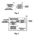
- Fig. 3 is a block diagram of arithmetic processing of the apparatus of this embodiment.
- Acceleration computing means 10 computes the vertical acceleration of a sprung structure.
- a relative velocity estimating section 12 estimates the relative velocity between sprung and unsprung structures in accordance with the acceleration computed by the acceleration computing means and the valve-opening-degree command value of the orifice portion of a shock absorber.
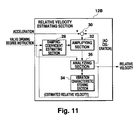
- Fig. 4 shows a relative-velocity estimating section 12A serving as a preferred structure of the relative velocity estimating section 12 shown in Fig. 3.
- a damping-force characteristic storing section 14 stores the previously measured damping-force characteristics of a shock absorber for a valve opening degree and stroke velocity in the form of the map data shown in Fig. 4.
- a damping-force estimating section 16 obtains the valve opening degree command for a shock absorber and the relative velocity between sprung and unsprung structures estimated in a previous control cycle, preferably in the last control cycle, reads the damping force generated due to the valve opening degree at that time and relative velocity from the data stored in the damping-force characteristic storing section 14, and estimates the read damping force as the present damping force of the shock absorber.
- an estimate-computing section 18 estimates the relative velocity between sprung and unsprung structures in accordance with the acceleration computed by an acceleration computing section 10 and the damping force estimated by the damping-force estimating section 16.
- the relative velocity estimating section 12A is a part of the control unit 58.
- the damping-force characteristic storing section 14 is a ROM (read only memory) provided for the control unit 58.
- the estimate-computing section 18 and the damping-force estimating section 16 are CPUs (central processing units) for performing the above described operations in accordance with a program stored in a ROM or the like.
- an output equation for computing a relative velocity y 2 from a parameter is defined as the following equation (3).
- y 2 C c2 ⁇ x c +C c2 ⁇ u
- x(k) denotes a parameter x c shown in the form of a discrete system.
- a state observer for the system for estimating the relative velocity is defined by the following equations (7) and (8).
- z(k) (I-L ⁇ C 1 )A ⁇ z(k-1)+L ⁇ y 1 (k)
- y 2h (k) C 2 ⁇ z(k)+D 2 ⁇ u(k) wherein z(k) denotes an estimated value of the parameter x(k) computed by the defined state observer.
- y 2h (k) denotes an estimated value of a relative velocity y 2 (k).
- Fig. 6 shows a block diagram of the observer defined by the equations (7) and (8).
- L in the equation (7) denotes the gain of a stationary Kalman filter, which can be obtained from the following equations (9) and (10).
- P [(APA T +BVB T ) -1 +C T W -1 C] -1
- L PC 1 T W -1
- V and W are design parameters which can be set by a designer in order to improve the estimation accuracy.
- a symbol P denotes the only positive constant value matrix meeting the equation (9).
- the coefficient matrixes A, B, C 1 , C 2 , D 1 and D 2 can be obtained from the constants such as the spring constant, sprung mass, and unsprung mass of the system shown in Fig. 2.
- the vertical acceleration y 1 (k) of a sprung structure can be computed in accordance with the output of an acceleration sensor provided on the sprung structure.
- an acceleration sensor for a sprung structure and directly use the acceleration detected by the sensor as the vertical acceleration y 1 (k).
- three acceleration sensors 60 are arranged so that they are not located on the same straight line and the attitude of a chassis (sprung structure) is obtained from an acceleration at the setting point to perform correction in accordance with the distances between the acceleration sensor and shock absorber attachment points and the center of gravity of the chassis.
- the chassis performs a heaving motion in which all part of the chassis move vertically in parallel.
- the detected value can directly be used as the vertical acceleration y 1 (k).
- the chassis includes a pitching motion.
- a damping force u(k) is estimated from the valve opening degree of a shock absorber and the output Y 2h (k) of a state observer, that is to say, the estimated relative velocity between sprung and unsprung structures.
- the valve opening degree uses a valve opening degree command sent from the control unit 58 to each shock absorber 56. Therefore, it is unnecessary to measure an actual valve opening degree, and thus it is unnecessary to use a sensor or the like.
- the relative velocity between sprung and unsprung structures uses the data one control cycle before. When a control cycle is much smaller than the change of the relative velocity between sprung and unsprung structures, it is estimated that the difference between the data one control cycle before and the present actual relative velocity is very small.
- the damping force characteristic of a shock absorber is previously measured by using a stroke velocity and a valve opening degree as parameters and stored in the form of characteristic map data as shown in Fig. 5.
- a valve opening degree and a stroke velocity are known, it is possible to estimate the damping force u(k) of a shock absorber at that time from the characteristic map data.
- the valve opening degree is known from the valve opening degree command and the stroke velocity equals the relative velocity between sprung and unsprung structures, it is possible to estimate the damping force at that time from these pieces of data. Strictly speaking, the estimated damping force is the damping force one control cycle before.
- the relative velocity y 2h (k) is estimated by using the above described vertical acceleration y 1 (k) of a sprung structure and the damping force u(k) in accordance with the equations (7) and (8).
- Fig. 7 shows estimated relative velocity (continuous line) and actual relative velocity (broken line) between sprung and unsprung structures of a vehicle to which the apparatus of this embodiment is applied when vibrating the vehicle only in the heaving direction.
- Figs. 9A, 9B, 10A and 10B show the results of trial computation of the vibration when using a shock absorber having the damping force characteristics shown in Fig. 8 for the single-wheel model with 2 degrees of freedom shown in Fig. 2.
- an observer gain is computed at a damping coefficient of 1,000 N ⁇ s/m by using a Kalman filter theory.
- vibration is executed by sine waves with a frequency of 0.5 to 5 Hz and an amplitude of 10 mm.
- Fig. 9A shows the relative velocity between sprung and unsprung structures actually measured at a valve opening degree of 100%.
- Fig. 9B shows an estimated value under the same condition.
- Fig. 9A shows the relative velocity between sprung and unsprung structures actually measured at a valve opening degree of 100%.
- Fig. 9B shows an estimated value under the same condition.
- Fig. 10A shows a measured value when the valve opening degree is fixed to an intermediate stage
- Fig. 10B shows an estimated value under the same condition.
- the damping coefficient at a valve opening degree of 100% depends on the stroke velocity, it approximately ranges between 1,000 and 2,800 N ⁇ s/m.
- the damping coefficient at the intermediate stage of the valve opening degree approximately ranges between 1,700 and 18,000 N ⁇ s/m.
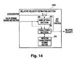
- Fig. 11 shows a relative velocity estimating section 12B which is another preferable structure of the relative velocity estimating section 12 shown in Fig. 3.
- a damping-coefficient estimating section 28 estimates a damping coefficient based on the previously-stored damping force characteristics in accordance with the relative velocity between sprung and unsprung structures estimated in a previous control cycle, preferably the last control cycle.
- a deviation computing section 30 computes the deviation of the vertical acceleration of the sprung structure computed by the acceleration computing section 10 from the estimated vertical acceleration of the sprung structure.
- An amplifying section 32 amplifies the deviation at a predetermined rate corresponding to the damping coefficient estimated by the damping-coefficient estimating section 28.
- a vibration characteristic storing section 34 previously stores vibration characteristics of the vehicle. The vibration characteristics include a sprung mass, unsprung mass, and spring constant and are stored as vibration models in accordance with these constants.
- An analyzing section 36 computes the acceleration of a sprung structure and the relative velocity between sprung and unsprung structures in accordance with the amplified acceleration deviation and the stored vibration models. In this case, the computed acceleration is used for operations by the deviation computing section 30.
- the relative velocity estimating section 12B is a part of the control unit 58.
- the vibration characteristic storing section 34 is a ROM provided for the control unit 58.
- the deviation computing section 30, amplifying section 32, and analyzing section 36 use a CPU to be operated by a predetermined program and a circuit element for performing predetermined operations.
- a damping force f c is shown by the following equation (14).
- Cs(Zs', ar) denotes that the damping coefficient Cs is a value determined by a relative velocity Zs and a valve opening degree ar. Moreover, it is assumed that the minimum value of the damping coefficient Cs is Cs min and the maximum value is Cs max .
- a Vmax A C +Cs max ⁇ BcN
- a Vmin A C +Cs min ⁇ BcN
- C V1max C C1 +Cs max ⁇ DuN
- x ch denotes an estimated signal of a parameter x c of a system to be computed by the defined state observer.
- y 2h denotes an estimated signal of a relative velocity y 2 .
- Figs. 12A, 12B, 13A and 13B show the results of trial computation of the relative velocity between sprung and unsprung structures of the single-wheel model with two degrees of freedom shown in Fig. 2 by using the above state observers.
- Fig. 8 shows the damping characteristics of a shock absorber.
- Figs. 12A, 12B, 13A and 13B show trial computation results when computing the observer gain L(q) in accordance with the damping coefficient Cs.
- the observer gain L(q) is computed by using the stationary Kalman filter theory at damping coefficients of 1,000 N ⁇ s/m and 65,600 N ⁇ s/m.
- Figs. 12A and 12B show the case of a valve opening degree of 100%
- Figs. 13A and 13B show the case of fixing a valve opening degree to an intermediate stage.
- Figs. 12A and 13A show measured values
- Figs. 12B and 13B show estimated values.
- the damping coefficients in the case of Figs. 12A and 12B show approx.
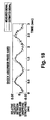
- Fig. 14 shows a relative velocity estimating section 12c which is still another preferable structure of the relative velocity estimating section 12 sown in Fig. 3.
- a deviation computing section 20 first computes the deviation of the vertical acceleration of a sprung structure computed by the acceleration computing section 10 from the estimated vertical acceleration of the sprung structure.
- a deviation amplifying section 22 amplifies the deviation at a predetermined rate corresponding to the above valve opening degree instruction.
- the vibration characteristics of the vehicle are previously stored in a vibration characteristic storing section 24.
- the vibration characteristics include a sprung mass, unsprung mass, and spring constant and are stored as vibration models in accordance with these constants.
- An analyzing section 26 computes the acceleration of a sprung structure and the relative velocity between sprung and unsprung structures in accordance with the amplified acceleration deviation and the stored vibration models. In this case, the computed acceleration is used for operations by the deviation computing section 20.
- the relative velocity estimating section 12C is a part of the control unit 58.
- the vibration characteristic storing section 24 is a ROM provided for the control unit 58.
- the deviation computing section 20, amplifying section 22, and analyzing section 36 use a CPU to be operated by a predetermined program and a circuit element for performing predetermined operations.
- the relative velocity estimating section 12C computes an observer gain L(p) in accordance with only the valve opening degree command ar.
- the observer gain L(p) is computed in accordance with the following equations (22) and (23).
- ar min denotes a valve opening degree command when fully opening a valve
- ar max denotes a valve opening degree command when fully closing the valve
- Figs. 15A, 15B, 16A and 16B show the results of trial computation of the relative velocity between sprung and unsprung structures of the single-wheel model with two degrees of freedom shown in Fig. 2 by using the above observers.
- the damping characteristics of a shock absorber are shown in Fig. 8.
- Figs. 15A, 15B, 16A and 16B show the results of trial computation the observer gain L(p) in accordance with the valve opening degree command ar.
- the observer gain L(p) is computed at damping coefficients of 1,000 N ⁇ s/m and 65,600 N ⁇ s/m by using the stationary Kalman filter theory.
- Figs. 15A and 15B show the case of a valve opening degree of 100%
- Figs. 16A and 16B show the case of fixing the valve opening degree to an intermediate stage.
- Figs. 15A and 16A show measured values
- Figs. 15B and 16B show estimated values.
- the damping coefficients in the case of Figs. 15A and 15B show approx.
- Figs. 17 and 18 the results of vibration tests on the actual vehicle shown in Fig. 1 in its heaving direction are shown by continuous lines.
- an observer gain is L(q) of the equation (21) computed in accordance with a damping coefficient and computed at damping coefficients of 1,000 N ⁇ s/m and 65,600 N ⁇ s/m by using the stationary Kalman filter theory.
- Fig. 17 shows the case of a valve opening degree of 100%
- Fig. 18 shows the case of a valve opening degree of 0%.
- the damping coefficient reaches approx. 1,000 to 2,800 N ⁇ s/m in the case of a valve opening degree of 100% and 65,600 N ⁇ s/m at most in the case of a valve opening degree of 0%.
- Figs. 17 and 18 denote the values obtained by differentiating the outputs of vehicle height sensors and show actual relative velocities between sprung and unsprung structures. From Figs. 17 and 18, it is found that a preferable estimation result can be obtained even if a damping coefficient varies greatly.
- Each of the above embodiments estimates a damping force from the information on valve opening degree or the relative velocity between sprung and unsprung structures computed in accordance with the information for valve opening degree and in a previous control cycle. Therefore, a high estimation accuracy is obtained. Moreover, by estimating the above relative velocity in accordance with an estimated value of the above damping force, a more-accurate relative velocity can be obtained.
Landscapes
- Engineering & Computer Science (AREA)
- Mechanical Engineering (AREA)
- Vehicle Body Suspensions (AREA)
Abstract
Description
- The present invention relates to an apparatus for computing the relative velocity between sprung and unsprung structures constituting factors of damping-force control in a suspension system using a variable damping-force shock absorber.
- The suspension of a vehicle is a system for connecting a sprung structure such as a chassis with an unsprung structure such as a wheel, which supports the sprung structure and greatly influences vibration, riding comfort, and maneuvering stability. The suspension includes such parts as a spring for moderating shocks from a road and a shock absorber for damping free vibration of the spring and controlling the velocity of attitude transition of the vehicle. As described above, there are various requirements for the suspension. However, these requirements conflict with each other. Therefore, in the case of design, an attempt is made to find a compromise by considering these requirements.
- In order to achieve the above suspension requirements at a high level, a technique is known which makes it possible to vary suspension characteristics. For example, there is a technique for varying the damping forces of a shock absorber in accordance with the state of a vehicle. For example, in a frequency region near a sprung-structure resonance frequency, damping force is increased so as to converge the free vibration in its early stage, otherwise in regions other than the above region, the damping force is decreased so as to absorb an input from the road surface by the suspension much more.
- This type of variable damping-force suspension is disclosed in the official gazette of Japanese Patent Laid-Open Publication No. Hei 6-106937. According to the art disclosed in this official gazette, a varying value of the damping force of a shock absorber is obtained to control the damping force by assuming that the damping force is generated proportionally to a certain parameter indicating a vehicle moving state shown by the vertical velocity of a sprung structure. By controlling the damping force, it is possible to decrease the number of sensors needed to detect the vehicle moving state. Moreover, to obtain the parameter showing the vehicle moving state, operations are performed by assuming that each operation factor varies linearly.
- As the characteristics of the damping force of a shock absorber, the damping force is generated depending on the velocity of a stroke including the direction and the valve opening degree of an orifice portion. According to the art disclosed in the official gazette, the damping force is generated proportionally to the parameter. Actually, however, the damping force is not generated proportionally to the parameter. Therefore, there is a problem that the damping force cannot necessarily be controlled at a high accuracy. Moreover, there is a problem that the parameter cannot be computed by a linear observer at a high accuracy because each operation factor actually changes in a nonlinear manner.
- The present invention is made to solve the above problems and its object is to provide a sprung- and unsprung-structure relative-velocity computing apparatus for accurately computing a stroke velocity serving as a factor for determining the damping force of a shock absorber, that is to say, the relative velocity between a sprung structure and an unsprung structure in order to perform a high-accuracy control while decreasing the number of sensors for detecting the moving state of a vehicle.
- A sprung- and unsprung-structure relative-velocity computing apparatus of the present invention computes the relative velocity between the sprung structure and unsprung structure of a vehicle connected through a shock absorber making it possible to vary damping forces by adjusting the valve opening degree of a fluid channel and a spring and particularly, has the following structures.
- (1) A configuration of the present invention has acceleration computing means for computing the vertical acceleration of a sprung structure and relative velocity estimating means for estimating the relative velocity between a sprung structure and an unsprung structure in accordance with the acceleration computed by the acceleration computing means and the valve-opening-degree command value of the orifice portion of a shock absorber.
According to the above structure, it is possible to estimate a relative velocity in accordance with the valve opening degree and the vertical acceleration of the sprung structure. Therefore, because a damping force is obtained in accordance with a valve opening degree serving as one of the factors for determining the damping force of a shock absorber, it is possible to estimate a relative velocity at a high accuracy. Moreover, because it is assumed that a valve opening degree is controlled in accordance with a control command of the valve opening degree of a damping-force-variable shock absorber, it is unnecessary to newly use means for detecting an actual valve opening degree, and therefore the structure is advantageous from the viewpoints of cost and weight. - (2) A preferable structure of relative velocity estimating means has damping-force characteristic storing means, damping-force estimating means, and estimate-computing means. These means will be described below. The damping-force characteristic storing means stores the damping force characteristic of a shock absorber for valve opening degree and stroke velocity in the form of map data. This damping-force characteristic is previously measured. The damping-force estimating means obtains the valve opening degree command for a shock absorber and the relative velocity between a sprung structure and an unsprung structure estimated in the previous control cycle, preferably in the last control cycle, reads the damping force generated at the then valve opening degree and relative velocity from the data stored in the damping-force characteristic storing means, and estimates the read damping force as the present damping force of the shock absorber. In this case, because the relative velocity between the sprung structure and unsprung structure becomes equal to the stroke velocity of the shock absorber, it is possible to use the characteristic stored in the damping-force characteristic storing means. Moreover, the estimate-computing means estimates the relative velocity between the sprung structure and unsprung structure in accordance with the acceleration computed by the acceleration computing means and the damping force estimated by the damping-force estimating means.
According to the above structure, when the damping-force characteristic of a shock absorber for a valve opening degree and velocity are stored, it is possible to estimate a damping force in accordance with the information on a valve opening degree and the relative velocity estimated in the previous control cycle. Moreover, it is possible to estimate the relative velocity in accordance with the estimated damping force and the vertical acceleration of the sprung structure. Therefore, because a damping force is obtained in accordance with a valve opening degree and a relative velocity which are factors for determining the damping force of a shock absorber, it is possible to estimate a relative velocity at a high accuracy. - (3) Another preferable structure of the relative velocity estimating means is provided with vibration characteristic storing means, deviation computing means, amplifying means, and vibration analyzing means. These means will be described below. In the case of the relative velocity estimating means, the deviation of the vertical acceleration of the sprung structure computed by the acceleration computing means from the estimated vertical acceleration of a sprung structure are first computed. The deviation is amplified at a predetermined rate corresponding to the valve opening degree command by the deviation amplifying means. Vibration characteristics of the vehicle are previously stored in the vibration characteristic storing means. The stored vibration characteristics include sprung mass, unsprung mass, and spring constant and are stored as vibration models in accordance with these constants.
The acceleration of a sprung structure and the relative velocity between sprung and unsprung structures are computed by the analyzing means in accordance with the amplified acceleration deviation and the stored vibration models. In this case, the computed acceleration is used for operations by the deviation computing means.
According to the above structure, it is possible to compare the estimated vertical acceleration of the sprung structure with the acceleration computed by the acceleration computing means and reflect the error between both accelerations on subsequent estimation, and moreover to vary the influence of the error on the estimating operation in accordance with a valve opening degree. Thereby, it is possible to compute a more accurate relative velocity. - (4) As still another preferable structure of the relative velocity estimating means is provided with vibration characteristic storing means, deviation computing means, damping-coefficient estimating means, amplifying means, and vibration analyzing means. The damping-coefficient estimating means estimates a damping coefficient based on previously stored damping-force characteristics in accordance with a valve opening degree command and the relative velocity between sprung and unsprung structures estimated in the previous control cycle, preferably the last control cycle. Moreover, the deviation computing means computes the deviation of the vertical acceleration of the sprung structure computed by the acceleration computing means from an estimated vertical acceleration of the sprung structure. The amplifying means amplifies the deviation at a predetermined rate corresponding to a damping coefficient estimated by the damping-coefficient estimating means. Moreover, vibration characteristics of the vehicle are previously stored in the vibration characteristic storing means. The vibration characteristics include sprung mass, unsprung mass, and spring constant and are stored as vibration models in accordance with these constants.
The analyzing means computes the acceleration of a sprung structure and the relative velocity between sprung and unsprung structures in accordance with the amplified acceleration deviation and the stored vibration models. In this case, the computed acceleration is used for the computation by the deviation computing means.
According to the above structure, it is possible to compare an estimated vertical acceleration of a sprung structure with an acceleration computed by the acceleration computing means and reflect the error between both accelerations on the subsequent estimation, and moreover to vary the influence of the error on the estimating operation in accordance with an estimated damping coefficient. Therefore, it is possible to compute a more accurate relative velocity. - (5) In the case of each configuration of the present invention described in (1) - (4), the acceleration computing means can be used as an acceleration sensor for detecting the acceleration of the shock absorber attachment point of the sprung structure. According to this structure, it is possible to use the acceleration detected by the acceleration sensor as the acceleration of the sprung structure.
- (6) Moreover, in the case of each configuration of the present invention described in (1) - (4), it is possible to use the acceleration computing means as a structure provided with a plurality of acceleration sensors provided for a sprung structure and attachment-point acceleration computing means for computing the acceleration of the shock absorber attachment point of the sprung structure in accordance with the acceleration detected by the acceleration sensors. The attachment-point acceleration computing means is able to compute the acceleration at the shock absorber attachment point from the position of the center of gravity of a vehicle, the shock absorber attachment point, and acceleration sensor installation positions by means of proportional computation and from the values detected by the acceleration sensors.
By locating two acceleration sensors at the front and the rear, it is possible to detect not only heaving in which the whole of a vehicle (sprung structure) is vertically displaced but also pitching in which the vehicle tilts forward and backward. Moreover, by locating two acceleration sensors at the right and the left, it is possible to detect not only heaving but also rolling in which the vehicle tilts rightward and leftward. Furthermore, by locating three acceleration sensors so that they are not located on the same straight line, it is possible to detect heaving, pitching, and rolling. -
- Fig. 1 is an illustration showing the partial layout of a suspension system of a vehicle;
- Fig. 2 is an analytic model of vehicle vibration;
- Fig. 3 is a structural block diagram of an embodiment of the present invention;
- Fig. 4 is a block diagram showing a part of the structure of an embodiment of the present invention;
- Fig. 5 is an illustration showing an example of damping force characteristics of a shock absorber;
- Fig. 6 is a block diagram showing the computation of relative velocity between sprung and unsprung structures;
- Fig. 7 is an illustration showing the comparison between an estimated value of vehicle vibration computed by the apparatus of the present embodiment and a measured value of vehicle vibration in an actual vehicle test;
- Fig. 8 is an illustration showing an example of damping force characteristics of a shock absorber;
- Fig. 9A is an illustration showing a measured value of vehicle vibration, and Fig. 9B is an illustration showing an estimated value of vehicle vibration computed by assuming that the observer gain L is constant;
- Fig. 10A is an illustration showing a measured value of vehicle vibration, and Fig. 10B is an illustration showing an estimated value of vehicle vibration computed by assuming that the observer gain L is constant;
- Fig. 11 is a block diagram showing a part of the structure of an embodiment of the present invention;
- Fig. 12A is an illustration showing a measured value of vehicle vibration, and Fig. 12B is an illustration showing an estimated value of vehicle vibration computed by the apparatus of the present embodiment for changing the observer gain L(q) in accordance with the damping coefficient Cs;
- Fig. 13A is an illustration showing a measured value of vehicle vibration, and Fig. 13B is an illustration showing an estimated value of vehicle vibration computed by the apparatus of the present embodiment for changing the observer gain L(q) in accordance with the damping coefficient Cs;
- Fig. 14 is a block diagram showing a part of the structure of an embodiment of the present invention;
- Fig. 15A is an illustration showing a measured value of vehicle vibration, and Fig. 15B is an illustration showing an estimated value of vehicle vibration computed by the apparatus of the present embodiment for changing the observer gain L(p) in accordance with the valve opening degree ar;
- Fig. 16A is an illustration showing a measured value of vehicle vibration, and Fig. 16B is an illustration showing an estimated value of vehicle vibration computed by the apparatus of the present embodiment for changing the observer gain L(p) in accordance with the valve opening degree ar;
- Fig. 17 is an illustration showing the comparison between an estimated value of vehicle vibration computed by the apparatus of the present embodiment for changing the observer gain L(q) in accordance with the damping coefficient Cs and a measured value of vehicle vibration in an actual vehicle test; and
- Fig. 18 is an illustration showing the comparison between an estimated value of vehicle vibration computed by the apparatus of the present embodiment for changing the observer gain L(q) in accordance with the damping coefficient Cs and a measured value of vehicle vibration in an actual vehicle test.
- The preferred embodiments of the present invention will be described below by referring to the accompanying drawings. Fig. 1 is an illustration showing the layout of parts of a vehicle provided with a variable-damping-force shock absorber. A
chassis 50 serving as a sprung structure is connected withwheels 51 serving as unsprung structures by suspensions includingshock absorbing systems springs shock absorbers - The shock absorber 56 generates a damping force using a resistance generated when fluid sealed inside the shock absorber 56 passes through an orifice. This embodiment makes it possible to adjust a damping force by controlling a valve opening degree and thereby varying the channel cross sections of the orifice. That is to say, when the valve opening degree is large and the channel cross section is large, the damping force decreases because the fluid passes smoothly through the channel. However, when the valve opening degree is small, the damping force increases because the fluid resistance increases. The valve opening degree can be varied by an actuator provided in a shock absorber and it is controlled in accordance with an instruction sent from a
control unit 58. Moreover, thecontrol unit 58 computes the relative velocity between thechassis 50 and thewheels 51 from the vertical acceleration of a vehicle detected byacceleration sensors - Fig. 2 shows a single wheel model including a variable-damping-force shock absorber. In Fig. 2, symbol Mu denotes the mass of a sprung structure (hereafter referred to as sprung mass) and Mw denotes the mass of an unsprung structure (hereafter referred to as unsprung mass). The masses of an arm and the spring 54 constituting a suspension and the shock absorber 5 are distributed to the sprung mass and the unsprung mass at an appropriate ratio. Symbol Ks denotes the spring constant of the spring 56, Kt denotes the spring constant of a tire, Cs denotes the fixed damping force of the shock absorber 56, and fc denotes the variable damping force of a shock absorber. Moreover, symbol Zu denotes the vertical displacement of a sprung structure, Zw denotes the vertical displacement of an unsprung structure, and Zr denotes the displacement of the surface of a road.
- Furthermore, in the subsequent description, a symbol ' denotes time differentiation of a variable provided with the symbol and a symbol " denotes double time differentiation. Therefore, Zu' denotes the velocity of a sprung structure and Zu" denotes the vertical acceleration of the sprung structure. Furthermore, a symbol T denotes the transposed matrix of a matrix provided with the symbol.
- The sprung- and unsprung-structure relative-velocity computing apparatus of this embodiment computes the relative velocity between sprung and unsprung structures of a vehicle connected through a shock absorber capable of varying damping forces by adjusting the valve opening degree of a fluid channel and a spring, and particularly has the following structure.
- Fig. 3 is a block diagram of arithmetic processing of the apparatus of this embodiment. Acceleration computing means 10 computes the vertical acceleration of a sprung structure. A relative
velocity estimating section 12 estimates the relative velocity between sprung and unsprung structures in accordance with the acceleration computed by the acceleration computing means and the valve-opening-degree command value of the orifice portion of a shock absorber. - Fig. 4 shows a relative-
velocity estimating section 12A serving as a preferred structure of the relativevelocity estimating section 12 shown in Fig. 3. A damping-forcecharacteristic storing section 14 stores the previously measured damping-force characteristics of a shock absorber for a valve opening degree and stroke velocity in the form of the map data shown in Fig. 4. A damping-force estimating section 16 obtains the valve opening degree command for a shock absorber and the relative velocity between sprung and unsprung structures estimated in a previous control cycle, preferably in the last control cycle, reads the damping force generated due to the valve opening degree at that time and relative velocity from the data stored in the damping-forcecharacteristic storing section 14, and estimates the read damping force as the present damping force of the shock absorber. In this case, because the relative velocity between sprung and unsprung structures becomes equal to the stroke velocity of the shock absorber, it is possible to use the characteristics stored in the damping-forcecharacteristic storing section 14. Moreover, an estimate-computing section 18 estimates the relative velocity between sprung and unsprung structures in accordance with the acceleration computed by anacceleration computing section 10 and the damping force estimated by the damping-force estimating section 16. - Specifically, the relative
velocity estimating section 12A is a part of thecontrol unit 58. Moreover, the damping-forcecharacteristic storing section 14 is a ROM (read only memory) provided for thecontrol unit 58. Furthermore, the estimate-computing section 18 and the damping-force estimating section 16 are CPUs (central processing units) for performing the above described operations in accordance with a program stored in a ROM or the like. - The arithmetic processing by the relative
velocity estimating section 12A will be described below in detail. - When showing the equation of motion of the system in Fig. 2 in the form of a state space expression, the following equation (1) is obtained.

- xc = (Zu' Zu Zw' Zw)T,
- u = fc,
- w = Zf, and
each of Ac, Bc and Gc is a coefficient matrix. - This is the state equation of a plant. In this case, xc denotes a parameter showing a moving state of the system. Moreover, because the vertical acceleration Zu" of a sprung structure is a variable which can be measured in this embodiment, the following equation (2) is obtained as an output equation.

- y1 = Zu",
- v is an measurement noise, and
each of Cc1 and Dc1 is a coefficient matrix. - Moreover, an output equation for computing a relative velocity y2 from a parameter is defined as the following equation (3).

- y2 = Zw'-Zu', and
- each of Cc2 and Dc2 is a coefficient matrix.
- When the above equations (1) to (3) are represented by discrete systems, the following equations (4) to (6) are obtained.


- x(k) denotes a parameter xc shown in the form of a discrete system.
- Then, a state observer for the system for estimating the relative velocity is defined by the following equations (7) and (8).


- The symbol L in the equation (7) denotes the gain of a stationary Kalman filter, which can be obtained from the following equations (9) and (10).


- Matrices V and W are design parameters which can be set by a designer in order to improve the estimation accuracy. A symbol P denotes the only positive constant value matrix meeting the equation (9).
- In the equations (7) and (8), the coefficient matrixes A, B, C1, C2, D1 and D2 can be obtained from the constants such as the spring constant, sprung mass, and unsprung mass of the system shown in Fig. 2.
- Moreover, the vertical acceleration y1(k) of a sprung structure can be computed in accordance with the output of an acceleration sensor provided on the sprung structure. In the case of the single wheel model shown in Fig. 2, it is possible to provide an acceleration sensor for a sprung structure and directly use the acceleration detected by the sensor as the vertical acceleration y1(k). In the case of the real vehicle shown in Fig. 1 or the like, it is difficult to set an acceleration sensor 60 to the chassis-side setting point of the shock absorber 56. Therefore, it is necessary to obtain the acceleration of a sprung structure by applying a predetermined correction to a value detected by the acceleration sensor 60. Specifically, three acceleration sensors 60 are arranged so that they are not located on the same straight line and the attitude of a chassis (sprung structure) is obtained from an acceleration at the setting point to perform correction in accordance with the distances between the acceleration sensor and shock absorber attachment points and the center of gravity of the chassis.
- For example, when the values detected by three acceleration sensors 60 are equal to each other, it is found that the chassis performs a heaving motion in which all part of the chassis move vertically in parallel. In this case, the detected value can directly be used as the vertical acceleration y1(k). Moreover, when the outputs of the two
acceleration sensors acceleration sensor 60c located close to the rear wheels, it is found that the chassis includes a pitching motion. When the chassis performs only a pitching motion, it is only necessary to correct an acceleration sensor output in accordance with the ratio of the distance between the center of gravity of the chassis and an acceleration sensor, to the distance between the center of gravity of the chassis and a shock absorber attachment point, and compute the vertical acceleration y1(k). The same is true for the case of a rolling motion. - Moreover, a damping force u(k) is estimated from the valve opening degree of a shock absorber and the output Y2h(k) of a state observer, that is to say, the estimated relative velocity between sprung and unsprung structures. The valve opening degree uses a valve opening degree command sent from the
control unit 58 to each shock absorber 56. Therefore, it is unnecessary to measure an actual valve opening degree, and thus it is unnecessary to use a sensor or the like. Moreover, the relative velocity between sprung and unsprung structures uses the data one control cycle before. When a control cycle is much smaller than the change of the relative velocity between sprung and unsprung structures, it is estimated that the difference between the data one control cycle before and the present actual relative velocity is very small. Furthermore, the damping force characteristic of a shock absorber is previously measured by using a stroke velocity and a valve opening degree as parameters and stored in the form of characteristic map data as shown in Fig. 5. When a valve opening degree and a stroke velocity are known, it is possible to estimate the damping force u(k) of a shock absorber at that time from the characteristic map data. As described above, because the valve opening degree is known from the valve opening degree command and the stroke velocity equals the relative velocity between sprung and unsprung structures, it is possible to estimate the damping force at that time from these pieces of data. Strictly speaking, the estimated damping force is the damping force one control cycle before. However, as described above, when a control cycle is much smaller than the cycle of relative velocity change, it is possible to make the difference between the damping force one control cycle before and its actual value very small. Particularly, for the cycle of the vibration generated in a suspension of a passenger car, approx. 10 Hz, which is the resonance frequency of an unsprung structure, and approx. 1 Hz, which is the resonance frequency of a sprung structure, are predominant. Therefore, by performing control at a frequency much higher (a cycle much shorter) than the above resonance frequencies, the problem caused by using the data one cycle before does not occur. - The relative velocity y2h(k) is estimated by using the above described vertical acceleration y1(k) of a sprung structure and the damping force u(k) in accordance with the equations (7) and (8).
- Fig. 7 shows estimated relative velocity (continuous line) and actual relative velocity (broken line) between sprung and unsprung structures of a vehicle to which the apparatus of this embodiment is applied when vibrating the vehicle only in the heaving direction.
- In the case of the above-described equations (7) and (8) or the state observer shown in Fig. 6, a model is analyzed by assuming that an observer gain L is constant. However, when the tilt of the damping force of a shock absorber, that is to say, the damping coefficient of the shock absorber changes greatly depending on the valve opening degree and stroke velocity of the shock absorber as shown in Fig. 8, it is not necessarily possible to estimate a parameter such as a relative velocity at a high accuracy in the case of a state observer with a constant observer gain L, that is to say, in the case of a linear state observer. A Kalman filter is one example of a linear state observers.
- Figs. 9A, 9B, 10A and 10B show the results of trial computation of the vibration when using a shock absorber having the damping force characteristics shown in Fig. 8 for the single-wheel model with 2 degrees of freedom shown in Fig. 2. In the case of this trial computation, an observer gain is computed at a damping coefficient of 1,000 N·s/m by using a Kalman filter theory. In this case, vibration is executed by sine waves with a frequency of 0.5 to 5 Hz and an amplitude of 10 mm. Fig. 9A shows the relative velocity between sprung and unsprung structures actually measured at a valve opening degree of 100%. Fig. 9B shows an estimated value under the same condition. Fig. 10A shows a measured value when the valve opening degree is fixed to an intermediate stage, and Fig. 10B shows an estimated value under the same condition. Though the damping coefficient at a valve opening degree of 100% depends on the stroke velocity, it approximately ranges between 1,000 and 2,800 N·s/m. Moreover, the damping coefficient at the intermediate stage of the valve opening degree approximately ranges between 1,700 and 18,000 N·s/m.
- In the case of Figs. 9A and 9B showing values close to the damping coefficient of 1,000 N·s/m which is a design condition, the measured value is almost equal to the estimated value and therefore a preferable result is obtained. In the case of a value separate from the design condition, however, a measured value is different from an estimated value. As described above, when a damping coefficient changes greatly, it is impossible to obtain a high accuracy from estimation by a linear observer, that is to say, a Kalman filter.
- The estimation of a relative velocity capable of corresponding to a case in which a damping coefficient varies greatly will be described below.
- Fig. 11 shows a relative
velocity estimating section 12B which is another preferable structure of the relativevelocity estimating section 12 shown in Fig. 3. A damping-coefficient estimating section 28 estimates a damping coefficient based on the previously-stored damping force characteristics in accordance with the relative velocity between sprung and unsprung structures estimated in a previous control cycle, preferably the last control cycle. Moreover, adeviation computing section 30 computes the deviation of the vertical acceleration of the sprung structure computed by theacceleration computing section 10 from the estimated vertical acceleration of the sprung structure. An amplifyingsection 32 amplifies the deviation at a predetermined rate corresponding to the damping coefficient estimated by the damping-coefficient estimating section 28. A vibrationcharacteristic storing section 34 previously stores vibration characteristics of the vehicle. The vibration characteristics include a sprung mass, unsprung mass, and spring constant and are stored as vibration models in accordance with these constants. - An analyzing
section 36 computes the acceleration of a sprung structure and the relative velocity between sprung and unsprung structures in accordance with the amplified acceleration deviation and the stored vibration models. In this case, the computed acceleration is used for operations by thedeviation computing section 30. - Specifically, the relative
velocity estimating section 12B is a part of thecontrol unit 58. Moreover, the vibrationcharacteristic storing section 34 is a ROM provided for thecontrol unit 58. Furthermore, thedeviation computing section 30, amplifyingsection 32, and analyzingsection 36 use a CPU to be operated by a predetermined program and a circuit element for performing predetermined operations. - The arithmetic processing by the relative
velocity estimating section 12B will be described below in detail. - When showing the above-described equation of motion of the system in Fig. 2 in the form of a state space expression, the following equation (11) is obtained.

- xc = (Zu' Zu Zw' Zw)T,
- w = Zr, and
each of Ac, Bc and Gc is a coefficient matrix. - This is the state equation of a plant. In this case, xc denotes a parameter showing a moving state of the above-described system. Moreover, because the vertical acceleration Zu" of a sprung structure is a variable which can be measured in the vehicle shown in Fig. 1, the following equation (12) is obtained as an output equation.

- y1 = Zu",
- v is an measurement noise, and
each of Cc1 and Dc1 is a coefficient matrix. - Moreover, an output equation for computing a relative velocity y2 from a parameter is defined as the following equation (13).

- y2 = Zw'-Zu', and
- Cc2 is a coefficient matrix.
- When assuming a damping coefficient as Cs and a valve opening degree command as ar, a damping force fc is shown by the following equation (14).

Zs =Zw-Zu. - In the equation (14), Cs(Zs', ar) denotes that the damping coefficient Cs is a value determined by a relative velocity Zs and a valve opening degree ar. Moreover, it is assumed that the minimum value of the damping coefficient Cs is Csmin and the maximum value is Csmax.
- When rewriting the equations (11) to (13) by using the damping coefficient Cs, the following equations (15), (16) and (17) are obtained.


- When Cs = Csmax, AV(q) and CV1(q) are assumed as AVmax and CV1max, respectively.
- When Cs = Csmin, AV(q) and CV1(q) are assumed as AVmin and CV1min, respectively.


- Then, a state observer for the above-described system for estimating the above relative velocity is defined by the following equations (19) and (20).


- In this case, xch denotes an estimated signal of a parameter xc of a system to be computed by the defined state observer. Moreover, y2h denotes an estimated signal of a relative velocity y2.
- L(q) in the equation (7) shows an observer gain and it is defined as shown below. It is assumed that the stationary Kalman filter gain for the equations (15) and (16) when a damping coefficient is equal to the minimum value Csmin is Lmin and the stationary Kalman filter gain for the equations (15) and (16) when the damping coefficient is equal to the maximum value Csmax is Lmax. Moreover, for observer gains computed at these end points, observer gains are set in accordance with the following equation (21) at points other than the end points:

- In order to compute the estimated value y2h of the relative velocity between sprung and unsprung structures in accordance with the observers defined by the equations (19) and (20), it is necessary to obtain fixed coefficient matrixes Ac, Bc, Gc, Cc1, Cc2 and Dc1 depending on the characteristic value of a system, the vertical acceleration y1 of a sprung structure, and the damping force fc. In this case, a coefficient matrix can easily be obtained from the mass of a sprung structure and a spring constant similarly to the above case in which the observer gain is constant and the acceleration y1 can be obtained from an acceleration sensor provided for a sprung structure. Moreover, the damping force fc is obtained by using the previously-measured damping force characteristics of a shock absorber shown in Fig. 8. Though a valve opening degree can actually be measured, this embodiment uses the valve opening degree command ar.
- Moreover, it is possible to obtain the damping force fc and damping coefficient Cs of a shock absorber based on the characteristic diagram in Fig. 8 by using the estimated value y2h of the relative velocity between sprung and unsprung structures one control cycle before. Furthermore, it is possible to obtain q from the equation (18) by using the damping coefficient Cs and obtain the observer gain L(q) from the equation (21).
- Thus, it is possible to estimate the relative velocity y2h between sprung and unsprung structures from the equations (19) and (20).
- In the case of detection of a sprung acceleration, it is possible to compute the acceleration of the chassis-side setting point of the shock absorber 56 by arranging three acceleration sensors so that they are not located on the same straight line.
- Figs. 12A, 12B, 13A and 13B show the results of trial computation of the relative velocity between sprung and unsprung structures of the single-wheel model with two degrees of freedom shown in Fig. 2 by using the above state observers. Moreover, Fig. 8 shows the damping characteristics of a shock absorber.
- Figs. 12A, 12B, 13A and 13B show trial computation results when computing the observer gain L(q) in accordance with the damping coefficient Cs. The observer gain L(q) is computed by using the stationary Kalman filter theory at damping coefficients of 1,000 N·s/m and 65,600 N·s/m. Moreover, Figs. 12A and 12B show the case of a valve opening degree of 100%, and Figs. 13A and 13B show the case of fixing a valve opening degree to an intermediate stage. Figs. 12A and 13A show measured values, and Figs. 12B and 13B show estimated values. The damping coefficients in the case of Figs. 12A and 12B show approx. 1,000 to 2,800 N·s/m and those in the case of Figs. 13A and 13B show approx. 1,700 to 18,000 N·s/m. Moreover, sine-wave vibration is executed at a frequency of 0.5 to 5 Hz and an amplitude of 10 mm. From these trial-computation results, it is found that a preferable estimation result can be obtained even if a damping coefficient changes greatly.
- Fig. 14 shows a relative velocity estimating section 12c which is still another preferable structure of the relative
velocity estimating section 12 sown in Fig. 3. In the case of the relativevelocity estimating section 12, adeviation computing section 20 first computes the deviation of the vertical acceleration of a sprung structure computed by theacceleration computing section 10 from the estimated vertical acceleration of the sprung structure. Adeviation amplifying section 22 amplifies the deviation at a predetermined rate corresponding to the above valve opening degree instruction. Moreover, the vibration characteristics of the vehicle are previously stored in a vibrationcharacteristic storing section 24. The vibration characteristics include a sprung mass, unsprung mass, and spring constant and are stored as vibration models in accordance with these constants. - An analyzing
section 26 computes the acceleration of a sprung structure and the relative velocity between sprung and unsprung structures in accordance with the amplified acceleration deviation and the stored vibration models. In this case, the computed acceleration is used for operations by thedeviation computing section 20. - Specifically, the relative
velocity estimating section 12C is a part of thecontrol unit 58. Moreover, the vibrationcharacteristic storing section 24 is a ROM provided for thecontrol unit 58. Furthermore, thedeviation computing section 20, amplifyingsection 22, and analyzingsection 36 use a CPU to be operated by a predetermined program and a circuit element for performing predetermined operations. - The arithmetic processing by the relative
velocity estimating section 12C will be described below in detail. - The relative
velocity estimating section 12C computes an observer gain L(p) in accordance with only the valve opening degree command ar. The observer gain L(p) is computed in accordance with the following equations (22) and (23).

- In this case, armin denotes a valve opening degree command when fully opening a valve and armax denotes a valve opening degree command when fully closing the valve.
- Other operations are the same as those carried out by the relative
velocity estimating section 12B shown in Fig. 11. - Figs. 15A, 15B, 16A and 16B show the results of trial computation of the relative velocity between sprung and unsprung structures of the single-wheel model with two degrees of freedom shown in Fig. 2 by using the above observers. The damping characteristics of a shock absorber are shown in Fig. 8.
- Figs. 15A, 15B, 16A and 16B show the results of trial computation the observer gain L(p) in accordance with the valve opening degree command ar. The observer gain L(p) is computed at damping coefficients of 1,000 N·s/m and 65,600 N·s/m by using the stationary Kalman filter theory. Moreover, Figs. 15A and 15B show the case of a valve opening degree of 100%, and Figs. 16A and 16B show the case of fixing the valve opening degree to an intermediate stage. Figs. 15A and 16A show measured values, and Figs. 15B and 16B show estimated values. The damping coefficients in the case of Figs. 15A and 15B show approx. 1,000 to 2,800 N·s/m and those in the case of Figs. 16A and 16B show approx. 1,700 to 6,500 N·s/m. Moreover, sine-wave vibration is executed at a frequency of 0.5 to 5 Hz and a amplitude of 10 mm. From these trial computation results, it is found that a preferable estimation result can be obtained even if a damping coefficient varies greatly.
- In Figs. 17 and 18, the results of vibration tests on the actual vehicle shown in Fig. 1 in its heaving direction are shown by continuous lines. For estimation of a relative velocity, an observer gain is L(q) of the equation (21) computed in accordance with a damping coefficient and computed at damping coefficients of 1,000 N·s/m and 65,600 N·s/m by using the stationary Kalman filter theory. Fig. 17 shows the case of a valve opening degree of 100%, and Fig. 18 shows the case of a valve opening degree of 0%. The damping coefficient reaches approx. 1,000 to 2,800 N·s/m in the case of a valve opening degree of 100% and 65,600 N·s/m at most in the case of a valve opening degree of 0%. Moreover, sine-wave vibration is executed at an amplitude of 10 mm and a frequency of 1 Hz. The broken lines in Figs. 17 and 18 denote the values obtained by differentiating the outputs of vehicle height sensors and show actual relative velocities between sprung and unsprung structures. From Figs. 17 and 18, it is found that a preferable estimation result can be obtained even if a damping coefficient varies greatly.
- Each of the above embodiments estimates a damping force from the information on valve opening degree or the relative velocity between sprung and unsprung structures computed in accordance with the information for valve opening degree and in a previous control cycle. Therefore, a high estimation accuracy is obtained. Moreover, by estimating the above relative velocity in accordance with an estimated value of the above damping force, a more-accurate relative velocity can be obtained.
- Furthermore, by measuring only the acceleration of a sprung structure in accordance with previously-measured damping force characteristics of a shock absorber and a valve opening degree instruction, it is possible to estimate the above relative velocity and moreover, to obtain a damping force in accordance with the estimated relative velocity. Therefore, no pressure sensor or vehicle height sensor in a shock absorber or no unsprung acceleration sensor is necessary. Thus, it is possible to decrease the cost and vehicle weight.
Claims (6)
- A sprung- and unsprung-structure relative-velocity computing apparatus for computing the relative velocity between a sprung structure and an unsprung structure of a vehicle connected through a shock absorber capable of varying damping forces by adjusting the valve opening degree of a fluid channel and a spring, said apparatus comprising:acceleration computing means for computing the vertical acceleration of said sprung structure, andrelative-velocity estimating means for estimating the relative velocity between a sprung structure and an unsprung structure of a vehicle in accordance with said computed acceleration and a valve-opening-degree command value for adjusting said valve opening degree.
- The sprung- and unsprung-structure relative-velocity computing apparatus according to Claim 1, wherein said relative-velocity estimating means is provided withdamping-force characteristic storing means for storing the damping-force characteristic of a shock absorber for valve-opening-degree instruction value and stroke velocity, said damping-force characteristic being previously measured,damping-force estimating means for estimating a damping force from said previously stored damping-force characteristic in accordance with said valve opening degree and the relative velocity estimated in a previous control cycle, andestimate-computing means for estimate-computing the relative velocity between the sprung structure and the unsprung structure of a vehicle in accordance with said detected acceleration and said estimated damping force.
- The sprung- and unsprung-structure relative-velocity computing apparatus according to Claim 1, wherein said relative-velocity estimating means is provided withvibration characteristic storing means for previously storing the vibration characteristic of said vehicle,deviation computing means for computing the deviation of said detected acceleration from an estimated vertical acceleration of a sprung structure,amplifying means for amplifying said deviation in accordance with said valve-opening-degree command value, andvibration analyzing means for estimating the vertical acceleration of said sprung structure and the relative velocity between sprung and unsprung structures.
- The sprung- and unsprung-structure relative-velocity computing apparatus according to Claim 1, wherein said relative velocity estimating means is provided withvibrational characteristic storing means for previously storing the vibration characteristic of said vehicle,deviation computing means for computing the deviation of said detected acceleration from an estimated vertical acceleration of a sprung structure,damping-coefficient estimating means for estimating the damping coefficient of a shock absorber in accordance with said valve-opening-degree command value and the relative velocity estimated in a previous control cycle,amplifying means for amplifying said deviation in accordance with said estimated damping coefficient, andvibration analyzing means for estimating the vertical acceleration of said sprung structure and the relative velocity between sprung and unsprung structures.
- The sprung- and unsprung-structure relative-velocity computing apparatus according to any one of Claims 1 to 4, wherein said acceleration computing means is an acceleration sensor for detecting the acceleration of an attachment point of the shock absorber of said sprung structure.
- The sprung- and unsprung-structure relative-velocity computing apparatus according to any one of Claims 1 to 4, wherein said acceleration computing means has a plurality of acceleration sensors provided for a sprung structure and attachment-point acceleration computing means for computing the acceleration of at least one attachment point of the shock absorber of said sprung structure in accordance with the acceleration detected by said acceleration sensors.
Priority Applications (1)
| Application Number | Priority Date | Filing Date | Title |
|---|---|---|---|
| EP04018982A EP1477342B1 (en) | 1996-05-22 | 1997-05-21 | Sprung- and unsprung-structure relative velocity computing apparatus for vehicle |
Applications Claiming Priority (3)
| Application Number | Priority Date | Filing Date | Title |
|---|---|---|---|
| JP127562/96 | 1996-05-22 | ||
| JP08127562A JP3118414B2 (en) | 1996-05-22 | 1996-05-22 | Vehicle sprung unsprung relative speed calculation device |
| JP12756296 | 1996-05-22 |
Related Child Applications (1)
| Application Number | Title | Priority Date | Filing Date |
|---|---|---|---|
| EP04018982A Division EP1477342B1 (en) | 1996-05-22 | 1997-05-21 | Sprung- and unsprung-structure relative velocity computing apparatus for vehicle |
Publications (3)
| Publication Number | Publication Date |
|---|---|
| EP0808734A2 true EP0808734A2 (en) | 1997-11-26 |
| EP0808734A3 EP0808734A3 (en) | 1999-07-21 |
| EP0808734B1 EP0808734B1 (en) | 2004-11-03 |
Family
ID=14963106
Family Applications (2)
| Application Number | Title | Priority Date | Filing Date |
|---|---|---|---|
| EP04018982A Expired - Lifetime EP1477342B1 (en) | 1996-05-22 | 1997-05-21 | Sprung- and unsprung-structure relative velocity computing apparatus for vehicle |
| EP97401117A Expired - Lifetime EP0808734B1 (en) | 1996-05-22 | 1997-05-21 | Suspension control apparatus with vehicle sprung- and unsprung- structure relative-velocity computing apparatus. |
Family Applications Before (1)
| Application Number | Title | Priority Date | Filing Date |
|---|---|---|---|
| EP04018982A Expired - Lifetime EP1477342B1 (en) | 1996-05-22 | 1997-05-21 | Sprung- and unsprung-structure relative velocity computing apparatus for vehicle |
Country Status (4)
| Country | Link |
|---|---|
| US (1) | US5987368A (en) |
| EP (2) | EP1477342B1 (en) |
| JP (1) | JP3118414B2 (en) |
| DE (2) | DE69737958T2 (en) |
Cited By (1)
| Publication number | Priority date | Publication date | Assignee | Title |
|---|---|---|---|---|
| DE10016896B4 (en) * | 1999-04-06 | 2010-09-02 | Toyota Jidosha Kabushiki Kaisha, Toyota-shi | Apparatus and method for estimating a kinetic state quantity for motor vehicles |
Families Citing this family (49)
| Publication number | Priority date | Publication date | Assignee | Title |
|---|---|---|---|---|
| JPH0552615U (en) * | 1991-12-10 | 1993-07-13 | 日本製箔株式会社 | Aluminum sheet mat for gas stove |
| JPH11170837A (en) * | 1997-12-16 | 1999-06-29 | Toyota Motor Corp | Height adjustment device |
| JP2000006632A (en) * | 1998-06-25 | 2000-01-11 | Isuzu Motors Ltd | Control device for vehicle suspension mechanism |
| KR100451288B1 (en) * | 2000-08-31 | 2004-10-06 | 도키코 가부시키 가이샤 | Suspension control system |
| DE10126933B4 (en) * | 2001-06-01 | 2004-08-26 | Continental Aktiengesellschaft | Method for regulating or controlling the damper force of adjustable dampers on vehicles |
| KR100550070B1 (en) * | 2003-11-26 | 2006-02-08 | 주식회사 만도 | Electronically controlled suspension system and damper damping force control method using the same |
| JP4546307B2 (en) * | 2005-03-30 | 2010-09-15 | 本田技研工業株式会社 | Control device for variable damping force damper |
| JP4199273B2 (en) * | 2006-08-29 | 2008-12-17 | 本田技研工業株式会社 | Vehicle state estimation device |
| WO2008138067A1 (en) * | 2007-05-15 | 2008-11-20 | University Of Technology, Sydney | A method and system for estimating parameters of a vehicle |
| FR2916409B1 (en) * | 2007-05-25 | 2009-08-21 | Snr Roulements Sa | METHOD FOR ESTIMATING A PARAMETER OF THE RUNNING OF A MOTOR VEHICLE USING A KALMAN FILTER |
| JP4930346B2 (en) * | 2007-11-29 | 2012-05-16 | トヨタ自動車株式会社 | Suspension system |
| US8839920B2 (en) | 2008-04-17 | 2014-09-23 | Levant Power Corporation | Hydraulic energy transfer |
| US10047817B2 (en) * | 2009-01-07 | 2018-08-14 | Fox Factory, Inc. | Method and apparatus for an adjustable damper |
| US10060499B2 (en) | 2009-01-07 | 2018-08-28 | Fox Factory, Inc. | Method and apparatus for an adjustable damper |
| US11306798B2 (en) | 2008-05-09 | 2022-04-19 | Fox Factory, Inc. | Position sensitive suspension damping with an active valve |
| US9452654B2 (en) | 2009-01-07 | 2016-09-27 | Fox Factory, Inc. | Method and apparatus for an adjustable damper |
| US8627932B2 (en) | 2009-01-07 | 2014-01-14 | Fox Factory, Inc. | Bypass for a suspension damper |
| US20100170760A1 (en) | 2009-01-07 | 2010-07-08 | John Marking | Remotely Operated Bypass for a Suspension Damper |
| JP5168567B2 (en) * | 2008-09-01 | 2013-03-21 | 日立オートモティブシステムズ株式会社 | State estimation device, suspension control device, and suspension system |
| US9140325B2 (en) | 2009-03-19 | 2015-09-22 | Fox Factory, Inc. | Methods and apparatus for selective spring pre-load adjustment |
| US12491961B2 (en) | 2008-11-25 | 2025-12-09 | Fox Factory, Inc. | Seat post |
| US10036443B2 (en) | 2009-03-19 | 2018-07-31 | Fox Factory, Inc. | Methods and apparatus for suspension adjustment |
| US11299233B2 (en) | 2009-01-07 | 2022-04-12 | Fox Factory, Inc. | Method and apparatus for an adjustable damper |
| US9038791B2 (en) | 2009-01-07 | 2015-05-26 | Fox Factory, Inc. | Compression isolator for a suspension damper |
| US12122205B2 (en) | 2009-01-07 | 2024-10-22 | Fox Factory, Inc. | Active valve for an internal bypass |
| US8955653B2 (en) | 2009-10-13 | 2015-02-17 | Fox Factory, Incorporated | Methods and apparatus for controlling a fluid damper |
| US10697514B2 (en) | 2010-01-20 | 2020-06-30 | Fox Factory, Inc. | Remotely operated bypass for a suspension damper |
| JP5723445B2 (en) | 2010-06-16 | 2015-05-27 | レバント パワー コーポレイション | Integrated energy generation damper |
| EP2530355B1 (en) | 2011-05-31 | 2019-09-04 | Fox Factory, Inc. | Apparatus for position sensitive and/or adjustable suspension damping |
| EP3567272B1 (en) | 2011-09-12 | 2021-05-26 | Fox Factory, Inc. | Methods and apparatus for suspension set up |
| US11279199B2 (en) | 2012-01-25 | 2022-03-22 | Fox Factory, Inc. | Suspension damper with by-pass valves |
| US10330171B2 (en) | 2012-05-10 | 2019-06-25 | Fox Factory, Inc. | Method and apparatus for an adjustable damper |
| CN104302492B (en) * | 2012-05-14 | 2016-08-24 | 日产自动车株式会社 | The control device of vehicle and the control method of vehicle |
| JP6059564B2 (en) * | 2013-03-13 | 2017-01-11 | Kyb株式会社 | Damper speed detection device |
| US8840118B1 (en) | 2013-03-15 | 2014-09-23 | Levant Power Corporation | Active suspension with on-demand energy flow |
| US9174508B2 (en) | 2013-03-15 | 2015-11-03 | Levant Power Corporation | Active vehicle suspension |
| WO2014145018A2 (en) | 2013-03-15 | 2014-09-18 | Levant Power Corporation | Active vehicle suspension improvements |
| US9702349B2 (en) | 2013-03-15 | 2017-07-11 | ClearMotion, Inc. | Active vehicle suspension system |
| EP3825156A1 (en) | 2013-04-23 | 2021-05-26 | ClearMotion, Inc. | Active suspension with structural actuator |
| US9702424B2 (en) | 2014-10-06 | 2017-07-11 | ClearMotion, Inc. | Hydraulic damper, hydraulic bump-stop and diverter valve |
| JP2017008659A (en) * | 2015-06-25 | 2017-01-12 | Kyb株式会社 | ZMP operation device and ZMP operation method |
| US10737546B2 (en) | 2016-04-08 | 2020-08-11 | Fox Factory, Inc. | Electronic compression and rebound control |
| JP2018058463A (en) * | 2016-10-04 | 2018-04-12 | アイシン精機株式会社 | Attenuation force control device |
| JP6822338B2 (en) * | 2017-07-19 | 2021-01-27 | トヨタ自動車株式会社 | Suspension control system |
| JP6923591B2 (en) * | 2019-04-12 | 2021-08-18 | 本田技研工業株式会社 | Electric suspension device |
| JP7327345B2 (en) | 2020-10-16 | 2023-08-16 | トヨタ自動車株式会社 | SUSPENSION STROKE RELATED VALUE ESTIMATING APPARATUS AND METHOD |
| CN112572086A (en) * | 2020-12-22 | 2021-03-30 | 华为技术有限公司 | Vehicle, control method of vehicle suspension and related equipment |
| DE102023115400B3 (en) | 2023-06-13 | 2024-06-27 | Dr. Ing. H.C. F. Porsche Aktiengesellschaft | Damping system for a wheel of a motor vehicle and motor vehicle |
| CN121234630A (en) * | 2025-12-02 | 2025-12-30 | 重庆蓝电汽车科技有限公司 | Suspension damping force estimation methods, devices, equipment, storage media, and program products |
Family Cites Families (10)
| Publication number | Priority date | Publication date | Assignee | Title |
|---|---|---|---|---|
| EP0264944B1 (en) * | 1986-10-24 | 1993-01-13 | Mazda Motor Corporation | Vehicle suspension system having variable suspension properties |
| US5434782A (en) * | 1991-05-20 | 1995-07-18 | General Motors Corporation | Suspension system state observer |
| US5235512A (en) * | 1991-06-24 | 1993-08-10 | Ford Motor Company | Self-tuning speed control for a vehicle |
| JP3080266B2 (en) * | 1992-05-21 | 2000-08-21 | 株式会社ユニシアジェックス | Vehicle suspension system |
| DE4218087C2 (en) * | 1992-06-01 | 2001-03-22 | Rolf Isermann | Method for determining the damping coefficient of a wheel suspension of a motor vehicle |
| US5425436A (en) * | 1992-08-26 | 1995-06-20 | Nippondenso Co., Ltd. | Automotive suspension control system utilizing variable damping force shock absorber |
| JP3131048B2 (en) * | 1992-09-30 | 2001-01-31 | マツダ株式会社 | Vehicle suspension device |
| JP3182021B2 (en) * | 1993-03-22 | 2001-07-03 | 株式会社ユニシアジェックス | Vehicle suspension system |
| EP0659598A1 (en) * | 1993-12-21 | 1995-06-28 | Unisia Jecs Corporation | Apparatus and method for controlling damping force characteristic of vehicular shock absorber |
| JP3374208B2 (en) * | 1995-07-06 | 2003-02-04 | 株式会社日立ユニシアオートモティブ | Vehicle suspension system |
-
1996
- 1996-05-22 JP JP08127562A patent/JP3118414B2/en not_active Expired - Lifetime
-
1997
- 1997-05-21 DE DE69737958T patent/DE69737958T2/en not_active Expired - Lifetime
- 1997-05-21 DE DE69731423T patent/DE69731423T2/en not_active Expired - Lifetime
- 1997-05-21 US US08/861,051 patent/US5987368A/en not_active Expired - Lifetime
- 1997-05-21 EP EP04018982A patent/EP1477342B1/en not_active Expired - Lifetime
- 1997-05-21 EP EP97401117A patent/EP0808734B1/en not_active Expired - Lifetime
Cited By (1)
| Publication number | Priority date | Publication date | Assignee | Title |
|---|---|---|---|---|
| DE10016896B4 (en) * | 1999-04-06 | 2010-09-02 | Toyota Jidosha Kabushiki Kaisha, Toyota-shi | Apparatus and method for estimating a kinetic state quantity for motor vehicles |
Also Published As
| Publication number | Publication date |
|---|---|
| EP0808734B1 (en) | 2004-11-03 |
| EP0808734A3 (en) | 1999-07-21 |
| DE69731423T2 (en) | 2005-10-27 |
| EP1477342A1 (en) | 2004-11-17 |
| DE69737958D1 (en) | 2007-09-06 |
| DE69731423D1 (en) | 2004-12-09 |
| DE69737958T2 (en) | 2008-04-10 |
| JPH09309315A (en) | 1997-12-02 |
| JP3118414B2 (en) | 2000-12-18 |
| US5987368A (en) | 1999-11-16 |
| EP1477342B1 (en) | 2007-07-25 |
Similar Documents
| Publication | Publication Date | Title |
|---|---|---|
| US5987368A (en) | Sprung- and unsprung-structure relative-velocity computing apparatus for vehicle | |
| US11884118B2 (en) | Damping control apparatus and method for a vehicle | |
| CN101365599B (en) | Method for determining at least one displacement state of a vehicle body | |
| US5550739A (en) | Semi-active suspension control system | |
| US5987367A (en) | Vehicle sprung- and unsprung-structure relative-velocity computing apparatus | |
| US5548536A (en) | Method for determining quantities which characterize the driving behavior | |
| US5475593A (en) | Distributed active vehicle suspension system | |
| US6684140B2 (en) | System for sensing vehicle global and relative attitudes using suspension height sensors | |
| US6701235B2 (en) | Suspension control system | |
| US5373445A (en) | Method and apparatus for determining dynamic force within an air spring suspension | |
| US11584183B2 (en) | Damping control apparatus and method for a vehicle | |
| US20030125857A1 (en) | Continuously variable semi-active suspension system using centrally located yaw rate and accelerometer sensors | |
| US20030212482A1 (en) | Method and apparatus for determining lateral velocity of a motor vehicle in closed form for all road and driving conditions | |
| JPH04505140A (en) | Land vehicle suspension control system | |
| CN114953886B (en) | A method and system for calculating the suspension state of a manned lunar rover | |
| US5563789A (en) | System to generate signals for control or regulation of a controllable or regulable chassis | |
| US20220118812A1 (en) | Suspension stroke related value estimation device and method | |
| US7571030B2 (en) | Estimation of vehicle roll rate and roll angle using suspension deflection sensors | |
| CN113544474B (en) | WIM sensor calibration and position selection and WIM sensor | |
| GB2271535A (en) | A vehicle suspension system | |
| SU847035A2 (en) | Device for measuring lay of the ground | |
| CN120697492A (en) | Method, system, vehicle and storage medium for calibrating parameters of suspension in vehicle | |
| KR19990017628A (en) | System factor detection system and its method in active suspension system |
Legal Events
| Date | Code | Title | Description |
|---|---|---|---|
| PUAI | Public reference made under article 153(3) epc to a published international application that has entered the european phase |
Free format text: ORIGINAL CODE: 0009012 |
|
| 17P | Request for examination filed |
Effective date: 19970530 |
|
| AK | Designated contracting states |
Kind code of ref document: A2 Designated state(s): DE FR GB |
|
| PUAL | Search report despatched |
Free format text: ORIGINAL CODE: 0009013 |
|
| AK | Designated contracting states |
Kind code of ref document: A3 Designated state(s): DE FR GB |
|
| 17Q | First examination report despatched |
Effective date: 20020724 |
|
| GRAP | Despatch of communication of intention to grant a patent |
Free format text: ORIGINAL CODE: EPIDOSNIGR1 |
|
| RTI1 | Title (correction) |
Free format text: SUSPENSION CONTROL APPARATUS WITH VEHICLE SPRUNG- AND UNSPRUNG- STRUCTURE RELATIVE-VELOCITY COMPUTING APPARATUS. |
|
| RTI1 | Title (correction) |
Free format text: SUSPENSION CONTROL APPARATUS WITH VEHICLE SPRUNG- AND UNSPRUNG- STRUCTURE RELATIVE-VELOCITY COMPUTING APPARATUS. |
|
| GRAS | Grant fee paid |
Free format text: ORIGINAL CODE: EPIDOSNIGR3 |
|
| GRAA | (expected) grant |
Free format text: ORIGINAL CODE: 0009210 |
|
| AK | Designated contracting states |
Kind code of ref document: B1 Designated state(s): DE FR GB |
|
| REG | Reference to a national code |
Ref country code: GB Ref legal event code: FG4D |
|
| REF | Corresponds to: |
Ref document number: 69731423 Country of ref document: DE Date of ref document: 20041209 Kind code of ref document: P |
|
| PLBE | No opposition filed within time limit |
Free format text: ORIGINAL CODE: 0009261 |
|
| STAA | Information on the status of an ep patent application or granted ep patent |
Free format text: STATUS: NO OPPOSITION FILED WITHIN TIME LIMIT |
|
| 26N | No opposition filed |
Effective date: 20050804 |
|
| ET | Fr: translation filed | ||
| REG | Reference to a national code |
Ref country code: GB Ref legal event code: 746 Effective date: 20070417 |
|
| REG | Reference to a national code |
Ref country code: FR Ref legal event code: PLFP Year of fee payment: 20 |
|
| PGFP | Annual fee paid to national office [announced via postgrant information from national office to epo] |
Ref country code: GB Payment date: 20160518 Year of fee payment: 20 Ref country code: DE Payment date: 20160518 Year of fee payment: 20 |
|
| PGFP | Annual fee paid to national office [announced via postgrant information from national office to epo] |
Ref country code: FR Payment date: 20160412 Year of fee payment: 20 |
|
| REG | Reference to a national code |
Ref country code: DE Ref legal event code: R071 Ref document number: 69731423 Country of ref document: DE |
|
| REG | Reference to a national code |
Ref country code: GB Ref legal event code: PE20 Expiry date: 20170520 |
|
| PG25 | Lapsed in a contracting state [announced via postgrant information from national office to epo] |
Ref country code: GB Free format text: LAPSE BECAUSE OF EXPIRATION OF PROTECTION Effective date: 20170520 |