EP0808726A1 - A ring binder - Google Patents
A ring binder Download PDFInfo
- Publication number
- EP0808726A1 EP0808726A1 EP96305656A EP96305656A EP0808726A1 EP 0808726 A1 EP0808726 A1 EP 0808726A1 EP 96305656 A EP96305656 A EP 96305656A EP 96305656 A EP96305656 A EP 96305656A EP 0808726 A1 EP0808726 A1 EP 0808726A1
- Authority
- EP
- European Patent Office
- Prior art keywords
- ring binder
- further characterized
- binder according
- ring
- members
- Prior art date
- Legal status (The legal status is an assumption and is not a legal conclusion. Google has not performed a legal analysis and makes no representation as to the accuracy of the status listed.)
- Granted
Links
Images


Classifications
-
- B—PERFORMING OPERATIONS; TRANSPORTING
- B42—BOOKBINDING; ALBUMS; FILES; SPECIAL PRINTED MATTER
- B42F—SHEETS TEMPORARILY ATTACHED TOGETHER; FILING APPLIANCES; FILE CARDS; INDEXING
- B42F13/00—Filing appliances with means for engaging perforations or slots
- B42F13/16—Filing appliances with means for engaging perforations or slots with claws or rings
- B42F13/20—Filing appliances with means for engaging perforations or slots with claws or rings pivotable about an axis or axes parallel to binding edges
- B42F13/22—Filing appliances with means for engaging perforations or slots with claws or rings pivotable about an axis or axes parallel to binding edges in two sections engaging each other when closed
- B42F13/26—Filing appliances with means for engaging perforations or slots with claws or rings pivotable about an axis or axes parallel to binding edges in two sections engaging each other when closed and locked when so engaged, e.g. snap-action
Definitions
- This invention relates to a ring binder and, in particular, a ring binder including a substantially rigid upper structure supporting a pivotable lower structure, to which a number of pairs of half-rings are mounted.
- Existing ring binders include different kinds of locking mechanisms for preventing accidental opening of the pairs of half-rings, thus allowing paper to fall off the binders.
- a locking mechanism if the ring binder is in a vertical position, the paper may force the pairs of half-rings to open, thus trapping one or more sheets of paper therebetween.
- the ring binder if there is no proper locking mechanism, in case the ring binder is turned over when holding a large amount of paper the paper may, by virtue of its weight, force the pairs of half-rings to open.
- ring binders including at either end thereof a lever which is operable to pivot the lower plates to selectively open and/or close pairs of ring members mounted on the plates.
- Such levers are movable among a first position in which the pairs of ring members are closed and are locked against any force applied thereon, a second position in which the pairs of ring members are closed but may be opened by force applied on any of the pairs of ring members, and a third position in which the pairs of ring members are open.
- a ring binder comprising a substantially rigid upper structure supporting a lower structure comprising a pair of plate members the plate members being pivotally movable between a first position in which the angle between the upper surfaces of the plate members is less than 180°, and a second position in which the angle between the upper surfaces of the plate members is more than 180°, a lock member to lock the lower structure and operating means to operate the lock member, characterized in that the lock member acts at a first location on the ring binder and the operating means acts at a second location on the ring binder, the first location being longitudinally distal on the ring binder from said second location.
- At least two pairs of half-ring members may be mounted to the lower structure and said first location may be adjacent a first pair of said half-ring members.
- said second location may be adjacent a second pair of said half-ring members.
- the lock member may be movable from a locked position in which it locks the lower structure against pivotal movement and an unlocked position in which the lower structure is pivotally movable.
- the ring binder may advantageously further comprise actuating means indirectly movable by the operating means to move the lock member from the locked position to the unlocked position.
- the lock member When in the locked position, the lock member may conveniently engage the upper surface of one of the plate members.
- At least part of the lock member When in the unlocked position, at least part of the lock member may suitably extend through aperture means of the lower structure.
- At least part of the actuating means may extend through the aperture means.
- the actuating means may comprise an end portion inclining at an acute angle to the lower structure when the plate members are on the same plane.
- a first of the pair of plate members may act on a first side of the actuating means to unlock the lower structure.
- a second of the pair of plate members may advantageously act on a second side of the actuating means to lock the lower structure.
- the end portion may conveniently be acutely inclined to the longitudinal axis of the ring binder.
- the aperture means may suitably comprise at least one edge angled to the longitudinal axis of the ring binder.
- the lower structure may act on the end portion during opening of the pairs of half-ring members.
- the lower structure may act on the end portion during closing of the pairs of half-ring members.
- the lock member may be swivellably movable relative the upper structure.
- the lock member may advantageously be fixedly engaged with the actuating means.
- the lock member may conveniently comprise at least one platelet.
- the lock member may suitably comprise a plurality of platelets.
- the operating means may comprise at least one of the pairs of half-ring members.
- said pair of half-ring members may be adjacent one longitudinal end of the ring binder.
- the operating means may comprise a plurality of pairs of half-ring members.
- the opening means may advantageously comprise two pairs of half-ring members each of which adjacent a respective longitudinal end of the ring binder.
- the operating means may conveniently comprise at least one lever member.
- the operating means may suitably comprise a plurality of lever members.
- the operating means may comprise two lever members each at a respective longitudinal end of the ring binder.
- lever member may be pivotally movable to act on an under surface of the lower structure to move the actuating means to move the lock member from the locked position to the unlocked position.
- the lower structure may be pivotally movable from its first position to its second position upon pivotal movement of firstly a first of said two lever members and subsequently of a second of said two lever members, and the lower structure is locked against pivotal movement from its first position to its second position upon pivotal movement firstly of the second of said two lever members and subsequently of the first of said two lever members.
- the lower structure may advantageously be pivotally movable from its first position to its second position upon pivotal movement of either of the two lever members.
- a ring binder according to a first embodiment of the present invention is generally designated as 10.
- the ring binder 10 includes an upper casing 12 supporting a pair of plates 14 a and 14 b to which three pairs of half-rings 16 a , 16 b and 16 c are mounted.
- the plates 14 a and 14 b are pivotally movable relative to each other, so that the pairs of half-rings 16 a , 16 b and 16 c may be selectively opened (when the angle between the upper surfaces of the plates 14 a and 14 b is more than 180°) or closed (when the angle between the upper surfaces of the plates 14 a and 14 b is less than 180°).
- the half-rings 16 a , 16 b and 16 c extend through three pairs of slots 18 a , 18 b and 18 c on the upper casing 12, which allow the half-rings 16 a , 16 b and 16 c to open or close.
- a hole 20 a and 20 b is a hole 20 a and 20 b , through which a rivet (not shown) may be received to secure the ring binder 10 to an article (not shown), e.g. a paperboard/plastic/metal cover.
- the ring binder 10 includes a lock 22 including a wire 24 with a lock element 26 fixedly crimped thereon.
- the wire 24 includes a shaft 28 which is secured to the middle line of lower surface of the upper casing 12 by three inturned parts 30 crimped therewith.
- the lock 22 is thus supported by the upper casing 12 between the half-rings 16 a and 16 b .
- the lock 22, the wire 24 and the lock element 26 are thus allowed to swivel about the longitudinal axis of the shaft 28.
- the lock 22 is partly received in a channel 29 on the underside of the upper casing 12.
- a corresponding ridge 31 is thus formed on the upper side of the upper casing 12. This arrangement also enhances the strength of the upper casing 12, and thus the ring binder 10.
- the half-rings 16 a , 16 b and 16 c may be returned to the closed position by pushing together any one of the three pairs of half-rings 16 a , 16 b and 16 c .
- the plate 14 a will act from above on the bent portion 38 of the wire 24, as shown by an arrow B in Fig. 7B, so that the lock 22 is caused to rotate about the shaft 28 in an anti-clockwise direction (according to Fig. 7B) to the position shown in Fig. 6B.
- Fig. 7B As shown in Fig.
- the bent portion 38 of the wire 24 inclines at an acute angle to the plane containing the plates 14 a and 14 b . There is sufficient space in the aperture 34 for the bent portion 38 to pass through during closing and opening of the half-rings 16 a , 16 b and 16 c .
- the bent portion 38 of the wire 24 may be acutely angled to the longitudinal axis of the ring binder 10. The effectiveness of this action can be still further enhanced by arranging a side of the aperture 34 to be angled to the longitudinal axis of the ring binder 10.
- the extent of return movement of the lock element 26 to its locked position is governed by the tongue 36, which prevents excessive movement of the lock element 26. This also prevents the distal end 32 of the wire 24 from being hidden in the cavity formed by the upper casing 12 and the plates 14 a and 14 b .
- Figs. 9 to 14 show a second embodiment of a ring binder according to the present invention generally designated as 100.
- the major difference of this embodiment from the first embodiment discussed above is the provision of two lock elements 102 and 104. Consequently, two tongues 106 and 108 are provided on the upper surface of a plate 110 b to govern the movements of the lock elements 102 and 104 back to the locked position, and two openings 112 and 114 are provided on the plate 110 b for allowing part of the lock elements 102 and 104 to pass through.
- Figs. 15 and 16 show a third embodiment of a ring binder according to the present invention generally designated as 200.
- the major difference of this embodiment from the first embodiment discussed above is the provision of two securing members 202 at each end of the ring binder 200.
- Each securing member 202 includes six arcuate pointed sectors 204 downwardly depending from the periphery of an orifice 206. It is thus possible to secure the ring binder 200 to a cardboard/paperboard cover without using any rivet.
- Figs. 17 to 21 show a fourth embodiment of a ring binder according to the present invention generally designated as 300.
- the ring binder 300 includes two levers 302 and 304, each at one end of the ring binder 300.
- the ring binder 300 also includes an upper casing 306 supporting a pair of plates 308 a and 308 b to which three pairs of half-rings 310 a , 310 b and 310 c are mounted.
- the plates 308 a and 308 b are pivotally movable relative to each other, so that the pairs of half-rings 310 a , 310 b and 310 c may be selectively opened or closed.
- Each of the levers 302 and 304 includes a ledge 312 and 314 respectively. When the levers 302 and 304 are pivoted outwardly, the edges 312 and 314 act on bottom surfaces of the plates 308 a and 308 b .
- the ring binder 300 includes a lock 316 including a wire 318 with two lock elements 320 fixedly crimped thereon.
- the lock 316 includes a shaft 322 which is secured to the lower surface of the upper casing 306. The lock 316 is thus supported by the upper casing 306 and may swivel about the longitudinal axis of the shaft 322.
- the ring binder 300 can only be opened by firstly pivoting the lever 302 outward so that the ledge 312 acts on the under surface of the plates 308 a and 308 b .
- the half-rings 310 a and 310 b are then partly opened.
- the plate 308 b will then act upon a bent portion 330 of the wire 318.
- the lock 316 will then be caused to rotate about the shaft 322 to move the lock elements 320 to disengage from the tongues 328 and the plate 308 b to the position as shown in Fig. 20.
- the lock elements 320 are aligned with openings 332, so that the plates 308 a and 308 b can be fully pivoted and the half-rings 310 a , 310 b and 310 c fully opened (as shown in Fig. 21) by subsequently pivoting the lever 304 outward.
- the ring binder 300 can be closed by pushing any of the pairs of half-rings 310 a , 310 b and 310 c together.
- the half-rings 310 a , 310 b and 310 c cannot, however, be opened by first pivoting the lever 304 outward, and subsequently the lever 302.
- Figs. 22 to 26 show a fifth embodiment of a ring binder according to the present invention generally designated as 400.
- the ring binder 400 is provided with a lock 402 including two lock members 404 and two distal ends 406. Each of the distal ends 406 of the lock 402, when in the position shown in Fig. 23, extends slightly through an aperture 408.
- either of the levers 410 and 412 may be pivoted outwardly to position as shown in Fig. 25.
- the lock members 404 are aligned with openings 414, thus allowing plates 416 a and 416 b to pivot further, by further outward pivoting movement of the same lever 410 or 412, to open three pairs of half-rings 418 a , 418 b and 418 c to the position as shown in Fig. 26.
- the ring binder 400 cannot be opened by actioning upon any of the pairs of half-rings 418 a , 418 b and 418 c .
Abstract
Description
- This invention relates to a ring binder and, in particular, a ring binder including a substantially rigid upper structure supporting a pivotable lower structure, to which a number of pairs of half-rings are mounted.
- Existing ring binders include different kinds of locking mechanisms for preventing accidental opening of the pairs of half-rings, thus allowing paper to fall off the binders. In the absence of a locking mechanism, if the ring binder is in a vertical position, the paper may force the pairs of half-rings to open, thus trapping one or more sheets of paper therebetween. In addition, if there is no proper locking mechanism, in case the ring binder is turned over when holding a large amount of paper the paper may, by virtue of its weight, force the pairs of half-rings to open.
- There are existing ring binders including at either end thereof a lever which is operable to pivot the lower plates to selectively open and/or close pairs of ring members mounted on the plates. Such levers are movable among a first position in which the pairs of ring members are closed and are locked against any force applied thereon, a second position in which the pairs of ring members are closed but may be opened by force applied on any of the pairs of ring members, and a third position in which the pairs of ring members are open.
- According to the present invention, there is provided a ring binder comprising a substantially rigid upper structure supporting a lower structure comprising a pair of plate members the plate members being pivotally movable between a first position in which the angle between the upper surfaces of the plate members is less than 180°, and a second position in which the angle between the upper surfaces of the plate members is more than 180°, a lock member to lock the lower structure and operating means to operate the lock member, characterized in that the lock member acts at a first location on the ring binder and the operating means acts at a second location on the ring binder, the first location being longitudinally distal on the ring binder from said second location.
- Advantageously, at least two pairs of half-ring members may be mounted to the lower structure and said first location may be adjacent a first pair of said half-ring members.
- Conveniently, said second location may be adjacent a second pair of said half-ring members.
- Suitably, the lock member may be movable from a locked position in which it locks the lower structure against pivotal movement and an unlocked position in which the lower structure is pivotally movable.
- The ring binder may advantageously further comprise actuating means indirectly movable by the operating means to move the lock member from the locked position to the unlocked position.
- When in the locked position, the lock member may conveniently engage the upper surface of one of the plate members.
- When in the unlocked position, at least part of the lock member may suitably extend through aperture means of the lower structure.
- Advantageously, at least part of the actuating means may extend through the aperture means.
- Conveniently, the actuating means may comprise an end portion inclining at an acute angle to the lower structure when the plate members are on the same plane.
- Suitably, a first of the pair of plate members may act on a first side of the actuating means to unlock the lower structure.
- A second of the pair of plate members may advantageously act on a second side of the actuating means to lock the lower structure.
- The end portion may conveniently be acutely inclined to the longitudinal axis of the ring binder.
- The aperture means may suitably comprise at least one edge angled to the longitudinal axis of the ring binder.
- Advantageously, the lower structure may act on the end portion during opening of the pairs of half-ring members.
- Conveniently, the lower structure may act on the end portion during closing of the pairs of half-ring members.
- Suitably, the lock member may be swivellably movable relative the upper structure.
- The lock member may advantageously be fixedly engaged with the actuating means.
- The lock member may conveniently comprise at least one platelet.
- The lock member may suitably comprise a plurality of platelets.
- Advantageously, the operating means may comprise at least one of the pairs of half-ring members.
- Conveniently, said pair of half-ring members may be adjacent one longitudinal end of the ring binder.
- Suitably, the operating means may comprise a plurality of pairs of half-ring members.
- The opening means may advantageously comprise two pairs of half-ring members each of which adjacent a respective longitudinal end of the ring binder.
- The operating means may conveniently comprise at least one lever member.
- The operating means may suitably comprise a plurality of lever members.
- Advantageously, the operating means may comprise two lever members each at a respective longitudinal end of the ring binder.
- Conveniently the lever member may be pivotally movable to act on an under surface of the lower structure to move the actuating means to move the lock member from the locked position to the unlocked position.
- Suitably, the lower structure may be pivotally movable from its first position to its second position upon pivotal movement of firstly a first of said two lever members and subsequently of a second of said two lever members, and the lower structure is locked against pivotal movement from its first position to its second position upon pivotal movement firstly of the second of said two lever members and subsequently of the first of said two lever members.
- The lower structure may advantageously be pivotally movable from its first position to its second position upon pivotal movement of either of the two lever members.
- The invention will now be described, by way of examples only, with reference to the accompanying drawings, wherein:-
- Fig. 1A shows a top perspective view of a first embodiment of a ring binder according to the present invention with the half-rings in a closed position;
- Fig. 1B shows a bottom perspective view of the ring binder shown in Fig. 1A;
- Fig. 2 shows an exploded view of the ring binder shown in Fig. 1A;
- Fig. 3 shows a bottom perspective view of the ring binder shown in Fig. 1A, with part of the lower structure removed for clarity purposes;
- Fig. 4 shows the ring binder of Fig. 1A with its lower structure in a partly moved position;
- Fig. 5 shows the ring binder of Fig. 1A with the half-rings in an open position;
- Fig. 6A shows a transverse sectional view of the ring binder shown in Fig. 1A across the lock member with the half-rings in the closed position;
- Fig. 6B shows a transverse sectional view of the ring binder shown in Fig. 1A across the key member with the half-rings in the closed position;
- Fig. 7A shows a transverse sectional view of the ring binder shown in Fig. 1A across the lock member with the half-rings in the open position;
- Fig. 7B shows a transverse sectional view of the ring binder shown in Fig. 1A across the key member with the half-rings in the open position;
- Fig. 8 shows a partial transverse sectional view of the ring binder shown in Fig. 1A across the key member with the plates on the same plane;
- Fig. 9 shows a top perspective view of a second embodiment of a ring binder according to the present invention with the half-rings in a closed position;
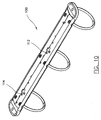
- Fig. 10 shows a bottom perspective view of the ring binder shown in Fig. 9;
- Fig. 11 shows an exploded view of the ring binder shown in Fig. 9;
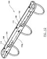
- Fig. 12 shows a bottom perspective view of the ring binder shown in Fig. 9, with part of the lower structure removed for clarity purposes;
- Fig. 13 shows the ring binder of Fig. 9 with its lower structure in a partly moved position;
- Fig. 14 shows the ring binder of Fig. 9 with the half-rings in an open position;
- Fig. 15 shows a top perspective view of a third embodiment of a ring binder according to the present invention with the half-rings in a closed position;
- Fig. 16 shows a bottom perspective view of the ring binder shown in Fig. 15;
- Fig. 17 shows a top perspective view of a fourth embodiment of a ring binder according to the present invention with the half-rings in a closed position;
- Fig. 18 shows a bottom perspective view of the ring binder shown in Fig. 17;
- Fig. 19 shows an exploded view of the ring binder shown in Fig. 17;
- Fig. 20 shows a bottom perspective view of the ring binder shown in Fig. 17 with some of the half-rings partly opened;
- Fig. 21 shows a bottom perspective view of the ring binder shown in Fig. 17 with all the half-rings fully opened;
- Fig. 22 shows a top perspective view of a fifth embodiment of a ring binder according to the present invention with the half-rings in a closed position;
- Fig. 23 shows a bottom perspective view of the ring binder shown in Fig. 22;
- Fig. 24 shows an exploded view of the ring binder shown in Fig. 22;
- Fig. 25 shows a bottom perspective view of the ring binder shown in Fig. 22 with some of the half-rings partly opened; and
- Fig. 26 shows a bottom perspective view of the ring binder shown in Fig. 22 with all the half-rings fully opened.
- As shown in Figs. 1A to 8, a ring binder according to a first embodiment of the present invention is generally designated as 10. The
ring binder 10 includes anupper casing 12 supporting a pair ofplates 14a and 14b to which three pairs of half-rings plates 14a and 14b are pivotally movable relative to each other, so that the pairs of half-rings plates 14a and 14b is more than 180°) or closed (when the angle between the upper surfaces of theplates 14a and 14b is less than 180°). The half-rings slots upper casing 12, which allow the half-rings ring binder 10 is ahole 20a and 20b, through which a rivet (not shown) may be received to secure thering binder 10 to an article (not shown), e.g. a paperboard/plastic/metal cover. - As shown more clearly in Fig. 2, the
ring binder 10 includes alock 22 including awire 24 with alock element 26 fixedly crimped thereon. As shown in Fig. 3, thewire 24 includes ashaft 28 which is secured to the middle line of lower surface of theupper casing 12 by threeinturned parts 30 crimped therewith. Thelock 22 is thus supported by theupper casing 12 between the half-rings lock 22, thewire 24 and thelock element 26 are thus allowed to swivel about the longitudinal axis of theshaft 28. - As shown more clearly in Figs. 6A to 7B, the
lock 22 is partly received in achannel 29 on the underside of theupper casing 12. A correspondingridge 31 is thus formed on the upper side of theupper casing 12. This arrangement also enhances the strength of theupper casing 12, and thus thering binder 10. - In the position when all the half-
rings distal end 32 of thewire 24 extends slightly through anaperture 34 of the plate 14a. In this position, thelock element 26 abuts against both the upper surface of theplate 14b and atongue 36. Any attempt to open the half-rings rings plate 14b, and consequently the plate 14a, is prevented from exhibiting any upward pivoting movement by reason of thelock element 26 acting against theplate 14b. - On the other hand, and as shown in Figs. 6A and 6B, if a pulling force is applied on the half-
rings 16a, theplate 14b will act upon abent portion 38 of thewire 24 in the direction shown by an arrow A. This will cause thelock 22 to rotate about theshaft 28 in a clockwise direction (according to Figs. 6A and 6B) to the position shown in Fig. 4. In this position, thewire 24 extends further through theaperture 34 of the plate 14a, and thelock element 26 is moved away from the upper surface of theplate 14b and thetongue 36, and aligns with anopening 40 of theplate 14b. Further pivoting movement of theplates 14a and 14b, and thus opening of all the half-rings rings 16a. - The half-
rings rings rings bent portion 38 of thewire 24, as shown by an arrow B in Fig. 7B, so that thelock 22 is caused to rotate about theshaft 28 in an anti-clockwise direction (according to Fig. 7B) to the position shown in Fig. 6B. As shown in Fig. 8, when theplates 14a and 14b are on the same plane, thebent portion 38 of thewire 24 inclines at an acute angle to the plane containing theplates 14a and 14b. There is sufficient space in theaperture 34 for thebent portion 38 to pass through during closing and opening of the half-rings bent portion 38 of thewire 24 may be acutely angled to the longitudinal axis of thering binder 10. The effectiveness of this action can be still further enhanced by arranging a side of theaperture 34 to be angled to the longitudinal axis of thering binder 10. - The extent of return movement of the
lock element 26 to its locked position is governed by thetongue 36, which prevents excessive movement of thelock element 26. This also prevents thedistal end 32 of thewire 24 from being hidden in the cavity formed by theupper casing 12 and theplates 14a and 14b. - It is clear from the foregoing discussion that, in the present invention, only one pair of half-rings, namely 16a, can be actioned upon to cause the
plates 14a and 14b to pivot, and thereby to open all the half-rings ring binder 10 is thus locked from any opening movement unless this specific pair of half-rings are actioned upon. In addition, it can be seen that the pair of half-rings 16a and thelock element 26 act on different longitudinal locations of theplates 14a and 14b of thering binder 10. On the other hand, all the half-rings ring binder 10. - Figs. 9 to 14 show a second embodiment of a ring binder according to the present invention generally designated as 100. The major difference of this embodiment from the first embodiment discussed above is the provision of two
lock elements tongues plate 110b to govern the movements of thelock elements openings plate 110b for allowing part of thelock elements - Figs. 15 and 16 show a third embodiment of a ring binder according to the present invention generally designated as 200. The major difference of this embodiment from the first embodiment discussed above is the provision of two securing
members 202 at each end of thering binder 200. Each securingmember 202 includes six arcuatepointed sectors 204 downwardly depending from the periphery of anorifice 206. It is thus possible to secure thering binder 200 to a cardboard/paperboard cover without using any rivet. - Figs. 17 to 21 show a fourth embodiment of a ring binder according to the present invention generally designated as 300. The
ring binder 300 includes twolevers ring binder 300. Thering binder 300 also includes anupper casing 306 supporting a pair ofplates 308a and 308b to which three pairs of half-rings plates 308a and 308b are pivotally movable relative to each other, so that the pairs of half-rings levers ledge levers edges plates 308a and 308b. - As can be seen in Fig. 19, the
ring binder 300 includes alock 316 including awire 318 with twolock elements 320 fixedly crimped thereon. As in the three embodiments discussed above, thelock 316 includes ashaft 322 which is secured to the lower surface of theupper casing 306. Thelock 316 is thus supported by theupper casing 306 and may swivel about the longitudinal axis of theshaft 322. - When all the half-
rings distal end 324 of thewire 318 extends slightly through anaperture 326 of the plate 308a. In this position, thelock elements 320 abut against the upper surface of theplate 308b andtongues 328. - In such an arrangement, the
ring binder 300 can only be opened by firstly pivoting thelever 302 outward so that theledge 312 acts on the under surface of theplates 308a and 308b. The half-rings plate 308b will then act upon abent portion 330 of thewire 318. Thelock 316 will then be caused to rotate about theshaft 322 to move thelock elements 320 to disengage from thetongues 328 and theplate 308b to the position as shown in Fig. 20. In this position, thelock elements 320 are aligned withopenings 332, so that theplates 308a and 308b can be fully pivoted and the half-rings lever 304 outward. Thering binder 300 can be closed by pushing any of the pairs of half-rings rings lever 304 outward, and subsequently thelever 302. - Figs. 22 to 26 show a fifth embodiment of a ring binder according to the present invention generally designated as 400. A major difference between this embodiment and the fourth embodiment discussed above is that the
ring binder 400 is provided with a lock 402 including twolock members 404 and two distal ends 406. Each of the distal ends 406 of the lock 402, when in the position shown in Fig. 23, extends slightly through anaperture 408. To open thering binder 400, either of thelevers lock members 404 are aligned withopenings 414, thus allowingplates same lever rings 418a, 418b and 418c to the position as shown in Fig. 26. In this arrangement, thering binder 400 cannot be opened by actioning upon any of the pairs of half-rings 418a, 418b and 418c. - It should be noted that the above only illustrates embodiments and examples in which the invention may be carried out, and that further modifications and/or alterations may be made to the examples without departing from the spirit of the invention.
Claims (29)
- A ring binder comprising a substantially rigid upper structure supporting a lower structure comprising a pair of plate members, the plate members being pivotally movable between a first position in which the angle between the upper surfaces of the plate members is less than 180°, and a second position in which the angle between the upper surfaces of the plate members is more than 180°, a lock member to lock the lower structure and operating means to operate the lock member, characterized in that the lock member acts at a first location on the ring binder and the operating means acts at a second location on the ring binder, the first location being longitudinally distal on the ring binder from said second location.
- A ring binder according to Claim 1 further characterized in that at least two pairs of half-ring members are mounted to the lower structure and said first location is adjacent a first pair of said half-ring members.
- A ring binder according to Claim 2 further characterized in that said second location is adjacent a second pair of said half-ring members.
- A ring binder according to Claim 1, 2 or 3 further characterized in that the lock member is movable from a locked position in which it locks the lower structure against pivotal movement and an unlocked position in which the lower structure is pivotally movable.
- A ring binder according to Claim 4 further characterized in that the ring binder further comprises actuating means indirectly movable by the operating means to move the lock member from the locked position to the unlocked position.
- A ring binder according to Claim 4 or 5 further characterized in that when in the locked position, the lock member engages the upper surface of one of the plate members.
- A ring binder according to Claim 4, 5 or 6 further characterized in that when in the unlocked position, at least part of the lock member extends through aperture means of the lower structure.
- A ring binder according to Claim 7 further characterized in that at least part of the actuating means extends through the aperture means.
- A ring binder according to any one of Claims 5 to 8 further characterized in that the actuating means comprises an end portion inclining at an acute angle to the lower structure when the plate members are on the same plane.
- A ring binder according to any one of Claims 5 to 9 further characterized in that a first of the pair of plate members acts on a first side of the actuating means to unlock the lower structure.
- A ring binder according to any one of Claims 5 to 10 further characterized in that a second of the pair of plate members acts on a second side of the actuating means to lock the lower structure.
- A ring binder according to any one of Claims 9 to 11 further characterized in that the end portion is acutely inclined to the longitudinal axis of the ring binder.
- A ring binder according to any one of Claims 5 to 12 further characterized in that the aperture means comprises at least one edge angled to the longitudinal axis of the ring binder.
- A ring binder according to any one of Claims 5 to 13 further characterized in that the lower structure acts on the end portion during opening of the pairs of half-ring members.
- A ring binder according to any one of Claims 5 to 14 further characterized in that the lower structure acts on the end portion during closing of the pairs of half-ring members.
- A ring binder according to any of the preceding claims further characterized in that the lock member is swivellably movable relative the upper structure.
- A ring binder according to any one of Claims 5 to 16 further characterized in that the lock member is fixedly engaged with the actuating means.
- A ring binder according to any of the preceding claims further characterized in that the lock member comprises at least one platelet.
- A ring binder according to Claim 18 further characterized in that the lock member comprises a plurality of platelets.
- A ring binder according to any of the preceding claims further characterized in that the operating means comprises at least one of the pairs of half-ring members.
- A ring binder according to Claim 20 further characterized in that said pair of half-ring members are adjacent one longitudinal end of the ring binder.
- A ring binder according to Claim 20 or 21 further characterized in that the operating means comprises a plurality of pairs of half-ring members.
- A ring binder according to any one of Claims 20 tor 22 further characterized in that the opening means comprises two pairs of half-ring members each of which adjacent a respective longitudinal end of the ring binder.
- A ring binder according to any one of Claims 1 to 19 further characterized in that the operating means comprises at least one lever member.
- A ring binder according to Claim 24 further characterized in that the operating means comprises a plurality of lever members.
- A ring binder according to Claim 24 or 25 further characterized in that the operating means comprises two lever members each at a respective longitudinal end of the ring binder.
- A ring binder according to any one of Claims 24 to 26 further characterized in that the lever member is pivotally movable to act on an under surface of the lower structure to move the actuating means to move the lock member from the locked position to the unlocked position.
- A ring binder according to Claim 26 or 27 further characterized in that the lower structure is pivotally movable from its first position to its second position upon pivotal movement of firstly a first of said two lever members and subsequently of a second of said two lever members, and the lower structure is locked against pivotal movement from its first position to its second position upon pivotal movement firstly of the second of said two lever members and subsequently of the first of said two lever members.
- A ring binder according to Claim 26 or 27 characterized in that the lower structure is pivotally movable from its first position to its second position upon pivotal movement of either of the two lever members.
Priority Applications (15)
| Application Number | Priority Date | Filing Date | Title |
|---|---|---|---|
| EP99200934A EP0933232A3 (en) | 1996-05-21 | 1996-07-31 | A ring binder |
| EP99200935A EP0933233A3 (en) | 1996-05-21 | 1996-07-31 | A ring binder |
| EP96305656A EP0808726B1 (en) | 1996-05-21 | 1996-07-31 | A ring binder |
| AU15191/97A AU1519197A (en) | 1996-05-21 | 1997-03-10 | A ring binder |
| NO971127A NO971127D0 (en) | 1996-07-31 | 1997-03-11 | ring Clip |
| CA002199690A CA2199690A1 (en) | 1996-05-21 | 1997-03-11 | Ring binder |
| US08/818,722 US5975785A (en) | 1996-05-21 | 1997-03-14 | Ring binder |
| IDP971452A ID16853A (en) | 1996-05-21 | 1997-05-01 | RING BINDER |
| BR9703128A BR9703128A (en) | 1996-05-21 | 1997-05-12 | Ring sorter |
| CN97112409A CN1062218C (en) | 1996-05-21 | 1997-05-16 | Ring type binding device |
| PL97320052A PL320052A1 (en) | 1996-05-21 | 1997-05-19 | Snap-ring type nbox file mechanism |
| JP9129448A JPH1044668A (en) | 1996-05-21 | 1997-05-20 | Ring binder |
| KR19970019618A KR970074016A (en) | 1996-05-21 | 1997-05-20 | |
| MXPA/A/1997/003701A MXPA97003701A (en) | 1996-05-21 | 1997-05-20 | An argol folder |
| HK98109685A HK1008944A1 (en) | 1996-05-21 | 1998-08-04 | Ring binder |
Applications Claiming Priority (3)
| Application Number | Priority Date | Filing Date | Title |
|---|---|---|---|
| EP96303636 | 1996-05-21 | ||
| EP96303636A EP0808725B1 (en) | 1996-05-21 | 1996-05-21 | A ring binder |
| EP96305656A EP0808726B1 (en) | 1996-05-21 | 1996-07-31 | A ring binder |
Related Child Applications (2)
| Application Number | Title | Priority Date | Filing Date |
|---|---|---|---|
| EP99200934A Division EP0933232A3 (en) | 1996-05-21 | 1996-07-31 | A ring binder |
| EP99200935A Division EP0933233A3 (en) | 1996-05-21 | 1996-07-31 | A ring binder |
Publications (2)
| Publication Number | Publication Date |
|---|---|
| EP0808726A1 true EP0808726A1 (en) | 1997-11-26 |
| EP0808726B1 EP0808726B1 (en) | 2000-04-26 |
Family
ID=26143717
Family Applications (3)
| Application Number | Title | Priority Date | Filing Date |
|---|---|---|---|
| EP96305656A Expired - Lifetime EP0808726B1 (en) | 1996-05-21 | 1996-07-31 | A ring binder |
| EP99200935A Withdrawn EP0933233A3 (en) | 1996-05-21 | 1996-07-31 | A ring binder |
| EP99200934A Withdrawn EP0933232A3 (en) | 1996-05-21 | 1996-07-31 | A ring binder |
Family Applications After (2)
| Application Number | Title | Priority Date | Filing Date |
|---|---|---|---|
| EP99200935A Withdrawn EP0933233A3 (en) | 1996-05-21 | 1996-07-31 | A ring binder |
| EP99200934A Withdrawn EP0933232A3 (en) | 1996-05-21 | 1996-07-31 | A ring binder |
Country Status (11)
| Country | Link |
|---|---|
| US (1) | US5975785A (en) |
| EP (3) | EP0808726B1 (en) |
| JP (1) | JPH1044668A (en) |
| KR (1) | KR970074016A (en) |
| CN (1) | CN1062218C (en) |
| AU (1) | AU1519197A (en) |
| BR (1) | BR9703128A (en) |
| CA (1) | CA2199690A1 (en) |
| HK (1) | HK1008944A1 (en) |
| ID (1) | ID16853A (en) |
| PL (1) | PL320052A1 (en) |
Cited By (1)
| Publication number | Priority date | Publication date | Assignee | Title |
|---|---|---|---|---|
| EP1203670A2 (en) * | 2000-11-01 | 2002-05-08 | World Wide Stationery Manufacturing Co. Ltd. | A ring binder mechanism |
Families Citing this family (36)
| Publication number | Priority date | Publication date | Assignee | Title |
|---|---|---|---|---|
| US6293722B1 (en) * | 1999-09-15 | 2001-09-25 | Acco Brands, Inc. | Binder Mechanism |
| AT408535B (en) * | 2000-01-27 | 2001-12-27 | Koloman Handler Ag | Ring mechanism |
| US7296946B2 (en) | 2001-11-30 | 2007-11-20 | Microsoft Corporation | Ring binder mechanism |
| US7549817B2 (en) | 2002-12-18 | 2009-06-23 | World Wide Stationery Mfg. Co., Ltd. | Ready lock ring binder mechanism |
| CA2500890A1 (en) | 2004-03-15 | 2005-09-15 | World Wide Stationery Manufacturing Company, Ltd. | Soft close ring binder mechanism with mating ring tips |
| US7275886B2 (en) * | 2004-03-15 | 2007-10-02 | World Wide Stationary Mfg. Co., Ltd. | Positive lock ring binder mechanism |
| US7661898B2 (en) * | 2004-03-15 | 2010-02-16 | World Wide Stationery Manufacturing Company, Limited | Soft close ring binder mechanism with reinforced travel bar |
| US7748922B2 (en) * | 2004-03-15 | 2010-07-06 | World Wide Stationery Manufacturing Company, Limited | Ring binder mechanism with dual pivot locking elements |
| US8002488B2 (en) * | 2004-03-15 | 2011-08-23 | World Wide Stationery Mfg. Co., Ltd. | Soft close ring binder mechanism |
| US7404685B2 (en) | 2004-12-30 | 2008-07-29 | World Wide Stationery Manufacturing Company, Limited | Ring binder mechanism spring biased to a locked position when ring members close |
| US7524128B2 (en) * | 2004-12-30 | 2009-04-28 | World Wide Stationery Manufacturing Company Limited | Ring binder mechanism spring biased to a locked position |
| US20060147254A1 (en) * | 2004-12-30 | 2006-07-06 | World Wide Stationery Mfg. Co., Ltd. | Lever for a ring mechanism |
| US7534064B2 (en) * | 2005-01-12 | 2009-05-19 | World Wide Stationery Mfg. Co., Ltd. | Ring mechanism biased to closed and locked position |
| US7726897B2 (en) | 2005-03-22 | 2010-06-01 | World Wide Stationery Mfg. Co., Ltd. | Ring binder mechanism |
| US7661899B2 (en) | 2005-03-22 | 2010-02-16 | World Wide Stationery Mfg. Co., Ltd. | Lever for a ring binder mechanism |
| US7665926B2 (en) * | 2005-05-06 | 2010-02-23 | World Wide Stationery Mfg. Co., Ltd. | Ring mechanism with spring biased travel bar |
| USD585935S1 (en) | 2007-01-05 | 2009-02-03 | World Wide Stationery Mfg. Co., Ltd. | Rectilinear binder ring |
| US10118431B2 (en) * | 2006-07-06 | 2018-11-06 | World Wide Stationery Mfg. Co., Ltd. | Ring for ring binder mechanism |
| US7731441B2 (en) | 2006-09-27 | 2010-06-08 | World Wide Stationery Mfg. Co., Ltd. | Ring binder mechanism |
| US7648302B2 (en) | 2006-09-27 | 2010-01-19 | World Wide Stationery Mfg. Co., Ltd. | Ring binder mechanism |
| US8047737B2 (en) | 2006-09-27 | 2011-11-01 | World Wide Stationery Mfg. Co., Ltd. | Ring binder mechanism |
| US20080175652A1 (en) * | 2007-01-18 | 2008-07-24 | World Wide Stationery Mfg. Co., Ltd. | Ring Binder Mechanism |
| US7654764B2 (en) * | 2007-05-16 | 2010-02-02 | World Wide Stationery Mfg. Co. Ltd. | Ring binder mechanism having blocking device |
| US8147160B2 (en) | 2007-10-31 | 2012-04-03 | World Wide Stationery Mfg. Co., Ltd. | Ring binder mechanism with polymeric housing and actuator |
| US7819602B2 (en) | 2007-10-31 | 2010-10-26 | World Wide Stationery Mfg. Co., Ltd. | Ring binder mechanism |
| US8162556B2 (en) | 2008-12-30 | 2012-04-24 | World Wide Stationery Mfg. Co., Ltd. | Actuator for a ring binder mechanism |
| DE102009005341A1 (en) | 2009-01-16 | 2010-07-22 | Hans Johann Horn | file mechanism |
| CN102126374B (en) | 2010-01-14 | 2013-10-30 | 国际文具制造厂有限公司 | Annular loose-leaf binder mechanism with dual-time-buffer actuator |
| JP2013528129A (en) | 2010-06-09 | 2013-07-08 | ワールド・ワイド・ステイショナリー・マニュファクチュアリング・カンパニー・リミテッド | Ring binder mechanism with a single structure |
| US8517624B2 (en) | 2010-11-12 | 2013-08-27 | R.R. Donnelly & Sons | Binder apparatus |
| US8899866B2 (en) | 2012-04-28 | 2014-12-02 | World Wide Stationary Mfg. Co. Ltd. | Ring binder mechanism with self-locking actuator |
| US10086639B2 (en) | 2013-03-15 | 2018-10-02 | Hans Johann Horn | Binder apparatus |
| US9522561B2 (en) | 2013-08-27 | 2016-12-20 | World Wide Stationery Mfg. Co., Ltd. | Ring binder mechanism |
| US9511617B2 (en) | 2013-10-31 | 2016-12-06 | World Wide Stationary Mfg. Co., Ltd. | Ring binder mechanism |
| CN105984250A (en) | 2015-02-05 | 2016-10-05 | 国际文具制造厂有限公司 | Annular binder with interlocking annular member |
| CN106142030A (en) * | 2015-04-02 | 2016-11-23 | 义乌市映程工艺品有限公司 | A kind of processing technology of cutting die storage volume |
Citations (3)
| Publication number | Priority date | Publication date | Assignee | Title |
|---|---|---|---|---|
| DE3119779A1 (en) * | 1981-05-19 | 1982-12-09 | Robert Krause Kg, 4992 Espelkamp | Mechanism for binding loose sheets |
| GB2254828A (en) * | 1991-04-15 | 1992-10-21 | Bensons Int Systems | A lockable ring binder mechanism |
| US5346325A (en) * | 1992-07-24 | 1994-09-13 | Seiichi Yamanoi | Paper holder having a locking device |
Family Cites Families (4)
| Publication number | Priority date | Publication date | Assignee | Title |
|---|---|---|---|---|
| US4571108A (en) * | 1982-11-26 | 1986-02-18 | Kurt Vogl | Locking ring binder mechanism with control slide |
| FR2675072B1 (en) * | 1991-04-15 | 1994-11-25 | Europ Propulsion | METHOD FOR MANUFACTURING LAMINATED STOPPERS, PARTICULARLY FOR ARTICULATIONS OF PROPELLER NOZZLES. |
| CN1040408C (en) * | 1991-05-31 | 1998-10-28 | 国际文具制造厂有限公司 | Ring binder |
| EP0808727B1 (en) * | 1996-05-21 | 2000-10-11 | Leco Stationery Manufacturing Co. Ltd. | A ring binder |
-
1996
- 1996-07-31 EP EP96305656A patent/EP0808726B1/en not_active Expired - Lifetime
- 1996-07-31 EP EP99200935A patent/EP0933233A3/en not_active Withdrawn
- 1996-07-31 EP EP99200934A patent/EP0933232A3/en not_active Withdrawn
-
1997
- 1997-03-10 AU AU15191/97A patent/AU1519197A/en not_active Abandoned
- 1997-03-11 CA CA002199690A patent/CA2199690A1/en not_active Abandoned
- 1997-03-14 US US08/818,722 patent/US5975785A/en not_active Expired - Fee Related
- 1997-05-01 ID IDP971452A patent/ID16853A/en unknown
- 1997-05-12 BR BR9703128A patent/BR9703128A/en not_active Application Discontinuation
- 1997-05-16 CN CN97112409A patent/CN1062218C/en not_active Expired - Fee Related
- 1997-05-19 PL PL97320052A patent/PL320052A1/en unknown
- 1997-05-20 KR KR19970019618A patent/KR970074016A/ko not_active Application Discontinuation
- 1997-05-20 JP JP9129448A patent/JPH1044668A/en active Pending
-
1998
- 1998-08-04 HK HK98109685A patent/HK1008944A1/en not_active IP Right Cessation
Patent Citations (3)
| Publication number | Priority date | Publication date | Assignee | Title |
|---|---|---|---|---|
| DE3119779A1 (en) * | 1981-05-19 | 1982-12-09 | Robert Krause Kg, 4992 Espelkamp | Mechanism for binding loose sheets |
| GB2254828A (en) * | 1991-04-15 | 1992-10-21 | Bensons Int Systems | A lockable ring binder mechanism |
| US5346325A (en) * | 1992-07-24 | 1994-09-13 | Seiichi Yamanoi | Paper holder having a locking device |
Cited By (2)
| Publication number | Priority date | Publication date | Assignee | Title |
|---|---|---|---|---|
| EP1203670A2 (en) * | 2000-11-01 | 2002-05-08 | World Wide Stationery Manufacturing Co. Ltd. | A ring binder mechanism |
| EP1203670A3 (en) * | 2000-11-01 | 2003-08-20 | World Wide Stationery Manufacturing Co. Ltd. | A ring binder mechanism |
Also Published As
| Publication number | Publication date |
|---|---|
| KR970074016A (en) | 1997-12-10 |
| EP0933232A2 (en) | 1999-08-04 |
| EP0933233A3 (en) | 1999-10-27 |
| BR9703128A (en) | 1998-10-27 |
| EP0933233A2 (en) | 1999-08-04 |
| MX9703701A (en) | 1998-06-30 |
| ID16853A (en) | 1997-11-13 |
| PL320052A1 (en) | 1997-11-24 |
| AU1519197A (en) | 1997-11-27 |
| US5975785A (en) | 1999-11-02 |
| JPH1044668A (en) | 1998-02-17 |
| HK1008944A1 (en) | 1999-05-21 |
| EP0933232A3 (en) | 1999-10-27 |
| EP0808726B1 (en) | 2000-04-26 |
| CN1062218C (en) | 2001-02-21 |
| CN1172025A (en) | 1998-02-04 |
| CA2199690A1 (en) | 1997-11-21 |
Similar Documents
| Publication | Publication Date | Title |
|---|---|---|
| EP0808726A1 (en) | A ring binder | |
| US5718529A (en) | Ring binder | |
| US6276862B1 (en) | Binder mechanism | |
| CA2494027C (en) | Soft close ring binder mechanism | |
| US5957611A (en) | Ring binder with dual angle ring metal | |
| US5354142A (en) | Ring binder | |
| US5868513A (en) | Ring binder | |
| US20090169287A1 (en) | Ring mechanism biased to closed and locked position | |
| GB2231536A (en) | Ring binder locking mechanism | |
| US4577985A (en) | Ring binder | |
| GB2309434A (en) | A lockable ring binder | |
| US5971649A (en) | Ring binder mechanism | |
| US6394684B2 (en) | Fastener for a folder | |
| US5755525A (en) | Ring binder | |
| US3944374A (en) | Loose leaf binder | |
| EP0512169A1 (en) | Ring binder | |
| CA2593624C (en) | Soft close ring binder mechanism | |
| MXPA97005517A (en) | Argol folder | |
| GB2309435A (en) | A lockable ring binder | |
| US775099A (en) | Temporary binder. | |
| MXPA97003700A (en) | An argol folder | |
| MXPA97003701A (en) | An argol folder | |
| CA2272496A1 (en) | A ring binder mechanism | |
| CA2272498A1 (en) | A housing for a ring binder mechanism | |
| GB2309429A (en) | A lockable ring binder |
Legal Events
| Date | Code | Title | Description |
|---|---|---|---|
| PUAI | Public reference made under article 153(3) epc to a published international application that has entered the european phase |
Free format text: ORIGINAL CODE: 0009012 |
|
| AK | Designated contracting states |
Kind code of ref document: A1 Designated state(s): AT BE CH DE DK ES FI FR GB GR IE IT LI LU MC NL PT SE |
|
| 17P | Request for examination filed |
Effective date: 19980302 |
|
| 17Q | First examination report despatched |
Effective date: 19981209 |
|
| GRAG | Despatch of communication of intention to grant |
Free format text: ORIGINAL CODE: EPIDOS AGRA |
|
| GRAG | Despatch of communication of intention to grant |
Free format text: ORIGINAL CODE: EPIDOS AGRA |
|
| GRAH | Despatch of communication of intention to grant a patent |
Free format text: ORIGINAL CODE: EPIDOS IGRA |
|
| GRAH | Despatch of communication of intention to grant a patent |
Free format text: ORIGINAL CODE: EPIDOS IGRA |
|
| GRAA | (expected) grant |
Free format text: ORIGINAL CODE: 0009210 |
|
| ITF | It: translation for a ep patent filed |
Owner name: BARZANO' E ZANARDO MILANO S.P.A. |
|
| AK | Designated contracting states |
Kind code of ref document: B1 Designated state(s): AT BE CH DE DK ES FI FR GB GR IE IT LI LU MC NL PT SE |
|
| PG25 | Lapsed in a contracting state [announced via postgrant information from national office to epo] |
Ref country code: LI Free format text: LAPSE BECAUSE OF FAILURE TO SUBMIT A TRANSLATION OF THE DESCRIPTION OR TO PAY THE FEE WITHIN THE PRESCRIBED TIME-LIMIT Effective date: 20000426 Ref country code: GR Free format text: LAPSE BECAUSE OF NON-PAYMENT OF DUE FEES Effective date: 20000426 Ref country code: CH Free format text: LAPSE BECAUSE OF FAILURE TO SUBMIT A TRANSLATION OF THE DESCRIPTION OR TO PAY THE FEE WITHIN THE PRESCRIBED TIME-LIMIT Effective date: 20000426 Ref country code: BE Free format text: LAPSE BECAUSE OF FAILURE TO SUBMIT A TRANSLATION OF THE DESCRIPTION OR TO PAY THE FEE WITHIN THE PRESCRIBED TIME-LIMIT Effective date: 20000426 Ref country code: AT Free format text: LAPSE BECAUSE OF FAILURE TO SUBMIT A TRANSLATION OF THE DESCRIPTION OR TO PAY THE FEE WITHIN THE PRESCRIBED TIME-LIMIT Effective date: 20000426 |
|
| REF | Corresponds to: |
Ref document number: 192091 Country of ref document: AT Date of ref document: 20000515 Kind code of ref document: T |
|
| REG | Reference to a national code |
Ref country code: CH Ref legal event code: EP |
|
| ET | Fr: translation filed | ||
| REF | Corresponds to: |
Ref document number: 69607942 Country of ref document: DE Date of ref document: 20000531 |
|
| REG | Reference to a national code |
Ref country code: IE Ref legal event code: FG4D |
|
| REG | Reference to a national code |
Ref country code: ES Ref legal event code: FG2A Ref document number: 2145387 Country of ref document: ES Kind code of ref document: T3 |
|
| PG25 | Lapsed in a contracting state [announced via postgrant information from national office to epo] |
Ref country code: SE Free format text: LAPSE BECAUSE OF FAILURE TO SUBMIT A TRANSLATION OF THE DESCRIPTION OR TO PAY THE FEE WITHIN THE PRESCRIBED TIME-LIMIT Effective date: 20000726 Ref country code: PT Free format text: LAPSE BECAUSE OF FAILURE TO SUBMIT A TRANSLATION OF THE DESCRIPTION OR TO PAY THE FEE WITHIN THE PRESCRIBED TIME-LIMIT Effective date: 20000726 |
|
| PG25 | Lapsed in a contracting state [announced via postgrant information from national office to epo] |
Ref country code: MC Free format text: THE PATENT HAS BEEN ANNULLED BY A DECISION OF A NATIONAL AUTHORITY Effective date: 20000731 Ref country code: LU Free format text: LAPSE BECAUSE OF NON-PAYMENT OF DUE FEES Effective date: 20000731 Ref country code: IE Free format text: LAPSE BECAUSE OF NON-PAYMENT OF DUE FEES Effective date: 20000731 |
|
| REG | Reference to a national code |
Ref country code: DK Ref legal event code: T3 |
|
| REG | Reference to a national code |
Ref country code: CH Ref legal event code: PL |
|
| PLBE | No opposition filed within time limit |
Free format text: ORIGINAL CODE: 0009261 |
|
| STAA | Information on the status of an ep patent application or granted ep patent |
Free format text: STATUS: NO OPPOSITION FILED WITHIN TIME LIMIT |
|
| 26N | No opposition filed | ||
| REG | Reference to a national code |
Ref country code: IE Ref legal event code: MM4A |
|
| PGFP | Annual fee paid to national office [announced via postgrant information from national office to epo] |
Ref country code: FR Payment date: 20010712 Year of fee payment: 6 Ref country code: FI Payment date: 20010712 Year of fee payment: 6 Ref country code: DK Payment date: 20010712 Year of fee payment: 6 |
|
| PGFP | Annual fee paid to national office [announced via postgrant information from national office to epo] |
Ref country code: ES Payment date: 20010719 Year of fee payment: 6 |
|
| PGFP | Annual fee paid to national office [announced via postgrant information from national office to epo] |
Ref country code: DE Payment date: 20010723 Year of fee payment: 6 |
|
| PGFP | Annual fee paid to national office [announced via postgrant information from national office to epo] |
Ref country code: GB Payment date: 20010725 Year of fee payment: 6 |
|
| PGFP | Annual fee paid to national office [announced via postgrant information from national office to epo] |
Ref country code: NL Payment date: 20010730 Year of fee payment: 6 |
|
| REG | Reference to a national code |
Ref country code: GB Ref legal event code: IF02 |
|
| PG25 | Lapsed in a contracting state [announced via postgrant information from national office to epo] |
Ref country code: GB Free format text: LAPSE BECAUSE OF NON-PAYMENT OF DUE FEES Effective date: 20020731 Ref country code: FI Free format text: LAPSE BECAUSE OF NON-PAYMENT OF DUE FEES Effective date: 20020731 Ref country code: DK Free format text: LAPSE BECAUSE OF NON-PAYMENT OF DUE FEES Effective date: 20020731 |
|
| PG25 | Lapsed in a contracting state [announced via postgrant information from national office to epo] |
Ref country code: ES Free format text: LAPSE BECAUSE OF NON-PAYMENT OF DUE FEES Effective date: 20020801 |
|
| PG25 | Lapsed in a contracting state [announced via postgrant information from national office to epo] |
Ref country code: NL Free format text: LAPSE BECAUSE OF NON-PAYMENT OF DUE FEES Effective date: 20030201 Ref country code: DE Free format text: LAPSE BECAUSE OF NON-PAYMENT OF DUE FEES Effective date: 20030201 |
|
| REG | Reference to a national code |
Ref country code: DK Ref legal event code: EBP |
|
| GBPC | Gb: european patent ceased through non-payment of renewal fee |
Effective date: 20020731 |
|
| PG25 | Lapsed in a contracting state [announced via postgrant information from national office to epo] |
Ref country code: FR Free format text: LAPSE BECAUSE OF NON-PAYMENT OF DUE FEES Effective date: 20030331 |
|
| NLV4 | Nl: lapsed or anulled due to non-payment of the annual fee |
Effective date: 20030201 |
|
| REG | Reference to a national code |
Ref country code: FR Ref legal event code: ST |
|
| REG | Reference to a national code |
Ref country code: ES Ref legal event code: FD2A Effective date: 20030811 |
|
| PG25 | Lapsed in a contracting state [announced via postgrant information from national office to epo] |
Ref country code: IT Free format text: LAPSE BECAUSE OF NON-PAYMENT OF DUE FEES;WARNING: LAPSES OF ITALIAN PATENTS WITH EFFECTIVE DATE BEFORE 2007 MAY HAVE OCCURRED AT ANY TIME BEFORE 2007. THE CORRECT EFFECTIVE DATE MAY BE DIFFERENT FROM THE ONE RECORDED. Effective date: 20050731 |