EP0808445B1 - Low stress casing joint configuration - Google Patents
Low stress casing joint configuration Download PDFInfo
- Publication number
- EP0808445B1 EP0808445B1 EP96903338A EP96903338A EP0808445B1 EP 0808445 B1 EP0808445 B1 EP 0808445B1 EP 96903338 A EP96903338 A EP 96903338A EP 96903338 A EP96903338 A EP 96903338A EP 0808445 B1 EP0808445 B1 EP 0808445B1
- Authority
- EP
- European Patent Office
- Prior art keywords
- cover
- housing
- joint
- casing assembly
- casing
- Prior art date
- Legal status (The legal status is an assumption and is not a legal conclusion. Google has not performed a legal analysis and makes no representation as to the accuracy of the status listed.)
- Expired - Lifetime
Links
- 239000000853 adhesive Substances 0.000 claims description 11
- 230000001070 adhesive effect Effects 0.000 claims description 11
- 229910010293 ceramic material Inorganic materials 0.000 claims description 6
- 239000002360 explosive Substances 0.000 claims description 6
- 230000000977 initiatory effect Effects 0.000 claims description 5
- PNEYBMLMFCGWSK-UHFFFAOYSA-N aluminium oxide Inorganic materials [O-2].[O-2].[O-2].[Al+3].[Al+3] PNEYBMLMFCGWSK-UHFFFAOYSA-N 0.000 claims description 2
- 239000008188 pellet Substances 0.000 description 3
- 239000000919 ceramic Substances 0.000 description 2
- 239000000356 contaminant Substances 0.000 description 2
- 230000007613 environmental effect Effects 0.000 description 2
- 230000013011 mating Effects 0.000 description 2
- 238000011084 recovery Methods 0.000 description 2
- 239000000565 sealant Substances 0.000 description 2
- 238000007789 sealing Methods 0.000 description 2
- 230000002411 adverse Effects 0.000 description 1
- 239000011248 coating agent Substances 0.000 description 1
- 238000000576 coating method Methods 0.000 description 1
- 238000011109 contamination Methods 0.000 description 1
- 238000005474 detonation Methods 0.000 description 1
- -1 e.g. Substances 0.000 description 1
- 230000000694 effects Effects 0.000 description 1
- 229920006332 epoxy adhesive Polymers 0.000 description 1
- 238000010304 firing Methods 0.000 description 1
- 239000007789 gas Substances 0.000 description 1
- 239000003999 initiator Substances 0.000 description 1
- 239000002184 metal Substances 0.000 description 1
- 238000005380 natural gas recovery Methods 0.000 description 1
- 230000002093 peripheral effect Effects 0.000 description 1
- 229920006267 polyester film Polymers 0.000 description 1
- 239000004065 semiconductor Substances 0.000 description 1
- 230000035939 shock Effects 0.000 description 1
- XLYOFNOQVPJJNP-UHFFFAOYSA-N water Substances O XLYOFNOQVPJJNP-UHFFFAOYSA-N 0.000 description 1
Images


Classifications
-
- F—MECHANICAL ENGINEERING; LIGHTING; HEATING; WEAPONS; BLASTING
- F42—AMMUNITION; BLASTING
- F42B—EXPLOSIVE CHARGES, e.g. FOR BLASTING, FIREWORKS, AMMUNITION
- F42B3/00—Blasting cartridges, i.e. case and explosive
- F42B3/28—Cartridge cases characterised by the material used, e.g. coatings
Definitions
- the present invention relates to casing for sealing explosive charges, electronic circuitry or other vulnerable articles against environmental pressures and/or contaminants, and more particularly to the configuration of a casing comprising a housing and a cover to be subjected to high external pressures.
- Casings of this type are known for encasing shaped charges, and they conventionally define a housing-cover joint that lies in a plane disposed at right angles to the axis of the charge.
- US-A-3 276 369 which forms a base for the preamble of claim 1, discloses a pulverable casing assembly comprising
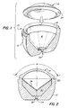
- a casing in accordance with one embodiment of the present invention may encase a shaped charge as shown in Figure 1.
- Casing 10 comprises a housing 12 and a cover 14 that are made from a ceramic material obtained from the Coors Ceramic Company under the trade designation AD-94 which comprises 94% alumina.
- Housing 12 defines a socket 16 that is dimensioned and configured to receive a shaped charge to be encased therein.
- Housing 12 defines a housing closure surface 18 which is a chamfer that extends around the opening of housing 12.
- a chamfer on cover 14 defines a cover closure surface 20.
- the improved pressure and temperature resistance of casings in accordance with the present invention permit the use of encased explosive charges and/or electronic components not only in oil and gas recovery applications, but also in deep sea demolition and other recovery activities.
Landscapes
- Engineering & Computer Science (AREA)
- General Engineering & Computer Science (AREA)
- Casings For Electric Apparatus (AREA)
- Crushing And Grinding (AREA)
- Greenhouses (AREA)
- Replacement Of Web Rolls (AREA)
- Branch Pipes, Bends, And The Like (AREA)
- Containers And Packaging Bodies Having A Special Means To Remove Contents (AREA)
Description
- a housing which defines a circular housing closure surface, said housing comprising a ceramic material;
- a cover on said housing, said cover comprising a ceramic material and defining a circular cover closure surface.
Claims (8)
- A pulverable casing assembly comprising:characterized by thata housing (12) comprising a ceramic material and defining a circular housing closure surface (18);a cover (14) on the housing (12), the cover comprising a ceramic material and defining a circular cover closure surface (20)the cover (14) further comprises a rounded conical exterior surface that defines a skirt angle (S) of about 120° andthe cover closure surface (20) is dimensioned and configured to engage the housing closure surface (18) to define a housing-cover joint (22) defining a joint angle (α) of about 130°.
- The casing assembly of claim 1 further comprising adhesive in the joint (22) to facilitate the establishment of a seal between the cover (14) and the housing (12).
- The casing assembly of claim 1 or claim 2 wherein the ceramic material comprises alumina.
- The casing assembly of claims 1, 2 or 3 wherein an interior surface (26) of the cover (14) has a rounding radius-to diameter ratio of about 0.68.
- The casing assembly of claim 4 wherein the exterior surface of the cover (14) is rounded to a radius of about 4,7 cm (1.84 inches) and has a diameter of about 8,3 cm (3.28 inches).
- The casing assembly of claim 1 further comprising a layer of adhesive in the housing-cover joint (22) to secure the cover (14) to the housing (12) and to provide a seal therebetween.
- The casing assembly of claim 1 further comprising:a fireset (36) and an associated initiation detonating charge (38) disposed in the housing (12); anda layer of adhesive in the housing-cover joint (22) to secure the cover (14) to the housing (12) and to provide a seal therebetween.
- Use of the casing assembly of claim 1 in an explosive penetrator.
Applications Claiming Priority (3)
| Application Number | Priority Date | Filing Date | Title |
|---|---|---|---|
| US08/379,701 US5505135A (en) | 1995-01-27 | 1995-01-27 | Low stress casing joint configuration |
| US379701 | 1995-01-27 | ||
| PCT/US1996/000070 WO1996023191A1 (en) | 1995-01-27 | 1996-01-11 | Low stress casing joint configuration |
Publications (3)
| Publication Number | Publication Date |
|---|---|
| EP0808445A1 EP0808445A1 (en) | 1997-11-26 |
| EP0808445A4 EP0808445A4 (en) | 1999-03-17 |
| EP0808445B1 true EP0808445B1 (en) | 2000-09-20 |
Family
ID=23498320
Family Applications (1)
| Application Number | Title | Priority Date | Filing Date |
|---|---|---|---|
| EP96903338A Expired - Lifetime EP0808445B1 (en) | 1995-01-27 | 1996-01-11 | Low stress casing joint configuration |
Country Status (8)
| Country | Link |
|---|---|
| US (1) | US5505135A (en) |
| EP (1) | EP0808445B1 (en) |
| AR (1) | AR000703A1 (en) |
| BR (1) | BR9606790A (en) |
| CA (1) | CA2209649C (en) |
| DE (1) | DE69610408T2 (en) |
| NO (1) | NO973098L (en) |
| WO (1) | WO1996023191A1 (en) |
Families Citing this family (13)
| Publication number | Priority date | Publication date | Assignee | Title |
|---|---|---|---|---|
| US5509356A (en) * | 1995-01-27 | 1996-04-23 | The Ensign-Bickford Company | Liner and improved shaped charge especially for use in a well pipe perforating gun |
| US6453817B1 (en) * | 1999-11-18 | 2002-09-24 | Schlumberger Technology Corporation | Shaped charge capsule |
| US7237486B2 (en) * | 2004-04-08 | 2007-07-03 | Baker Hughes Incorporated | Low debris perforating gun system for oriented perforating |
| US20140291022A1 (en) * | 2013-03-29 | 2014-10-02 | Schlumberger Technology Corporation | Amorphous shaped charge component and manufacture |
| CN111094889A (en) | 2017-09-14 | 2020-05-01 | 德力能欧洲有限公司 | Shaped charge liners, shaped charges for high temperature wellbore operations, and methods of perforating a wellbore therewith |
| CA3083047A1 (en) | 2017-11-29 | 2019-06-06 | DynaEnergetics Europe GmbH | Closure member and encapsulated slotted shaped charge with closure member |
| US11378363B2 (en) | 2018-06-11 | 2022-07-05 | DynaEnergetics Europe GmbH | Contoured liner for a rectangular slotted shaped charge |
| IL261899A (en) * | 2018-09-20 | 2019-02-28 | Cohen David | An explosion concentration facility |
| CN110953943A (en) * | 2019-05-08 | 2020-04-03 | 中北大学 | Active material blasting device that factor of safety is high |
| USD981345S1 (en) * | 2020-11-12 | 2023-03-21 | DynaEnergetics Europe GmbH | Shaped charge casing |
| US12320238B2 (en) | 2020-12-21 | 2025-06-03 | DynaEnergetics Europe GmbH | Encapsulated shaped charge |
| US12253339B2 (en) | 2021-10-25 | 2025-03-18 | DynaEnergetics Europe GmbH | Adapter and shaped charge apparatus for optimized perforation jet |
| US12312925B2 (en) | 2021-12-22 | 2025-05-27 | DynaEnergetics Europe GmbH | Manually oriented internal shaped charge alignment system and method of use |
Family Cites Families (13)
| Publication number | Priority date | Publication date | Assignee | Title |
|---|---|---|---|---|
| US2698575A (en) * | 1949-07-02 | 1955-01-04 | Inst Of Inventive Res | Charge for seismic exploration |
| US2927534A (en) * | 1956-02-06 | 1960-03-08 | Pgac Dev Company | Perforating device and method of perforating wells |
| US2974589A (en) * | 1957-06-03 | 1961-03-14 | Du Pont | Jet perforators |
| US3078797A (en) * | 1960-11-08 | 1963-02-26 | Schlumberger Well Surv Corp | Strip gun improvements |
| US3276369A (en) * | 1964-07-17 | 1966-10-04 | Schlumberger Well Surv Corp | Shaped charge device |
| FR1447246A (en) * | 1965-05-18 | 1966-07-29 | Schlumberger Prospection | Explosive charge for putting the boreholes into production |
| US3636875A (en) * | 1970-06-29 | 1972-01-25 | Schlumberger Technology Corp | Shaped charge devices for wire carriers |
| US3659658A (en) * | 1970-09-28 | 1972-05-02 | Schlumberger Technology Corp | Well perforating apparatus |
| USRE31420E (en) * | 1978-03-17 | 1983-10-18 | Jet Research Center, Inc. | Powdered metal casing for perforating charge and its method of manufacture |
| US4273047A (en) * | 1978-12-11 | 1981-06-16 | Jet Research Center, Inc. | Apparatus for perforating a well and its method of assembly |
| US4253523A (en) * | 1979-03-26 | 1981-03-03 | Ibsen Barrie G | Method and apparatus for well perforation and fracturing operations |
| USH319H (en) * | 1986-11-18 | 1987-08-04 | The United States Of America As Represented By The Secretary Of The Navy | Gun blast diffuser |
| DE3742290A1 (en) * | 1987-12-14 | 1989-06-22 | Dynamit Nobel Ag | HOLLOW CHARGE WITH SITU BARRIER |
-
1995
- 1995-01-27 US US08/379,701 patent/US5505135A/en not_active Expired - Fee Related
-
1996
- 1996-01-11 EP EP96903338A patent/EP0808445B1/en not_active Expired - Lifetime
- 1996-01-11 BR BR9606790A patent/BR9606790A/en not_active Application Discontinuation
- 1996-01-11 CA CA002209649A patent/CA2209649C/en not_active Expired - Fee Related
- 1996-01-11 WO PCT/US1996/000070 patent/WO1996023191A1/en not_active Ceased
- 1996-01-11 AR ARP960100964A patent/AR000703A1/en unknown
- 1996-01-11 DE DE69610408T patent/DE69610408T2/en not_active Expired - Fee Related
-
1997
- 1997-07-03 NO NO973098A patent/NO973098L/en not_active Application Discontinuation
Also Published As
| Publication number | Publication date |
|---|---|
| BR9606790A (en) | 1997-12-30 |
| US5505135A (en) | 1996-04-09 |
| NO973098L (en) | 1997-09-26 |
| CA2209649C (en) | 2000-07-18 |
| DE69610408D1 (en) | 2000-10-26 |
| DE69610408T2 (en) | 2001-01-25 |
| AR000703A1 (en) | 1997-08-06 |
| NO973098D0 (en) | 1997-07-03 |
| EP0808445A1 (en) | 1997-11-26 |
| MX9705658A (en) | 1997-10-31 |
| EP0808445A4 (en) | 1999-03-17 |
| WO1996023191A1 (en) | 1996-08-01 |
| CA2209649A1 (en) | 1996-08-01 |
Similar Documents
| Publication | Publication Date | Title |
|---|---|---|
| EP0808445B1 (en) | Low stress casing joint configuration | |
| AU648577B2 (en) | Transfer apparatus adapted for transferring an explosive train through an externally pressurized secondary explosive bulkhead | |
| US5155293A (en) | Safety booster for explosive systems | |
| US20220178230A1 (en) | Retrievable perforating gun assembly and components | |
| US4037538A (en) | Device for firing an electric detonator | |
| CA1303968C (en) | Through bulkhead explosive initiator for oil well usage | |
| CA2034036C (en) | Detonation transfer apparatus for initiating detonation of an insensitive detonating cord utilizing an initiating compound, flyer and shock reflector | |
| US3233688A (en) | Casing cutter | |
| GB1598002A (en) | Electric igniter | |
| CN1217784A (en) | Electronic Explosive Detonation Device | |
| KR910008234B1 (en) | Metal pipe joints and manufacturing method | |
| CA1154630A (en) | Binary electroexplosive device | |
| CN106123718A (en) | Non-contact shaped explosive device | |
| US6453817B1 (en) | Shaped charge capsule | |
| CA1280315C (en) | Explosive projectiles | |
| US5641941A (en) | Method and apparatus for electrical connections to encased electronic devices | |
| US4370929A (en) | Contact head | |
| MXPA97005658A (en) | Configuration of low spheel envelope board | |
| GB1339975A (en) | Bursting disc assembly | |
| CN216482576U (en) | Detonation network system for annular energy-gathering charge unit | |
| CN215296034U (en) | Blasting initiating explosive device | |
| RU2080545C1 (en) | Cartridge for commercial explosive | |
| US3641936A (en) | Composite shell with ceramic base | |
| ZA200409576B (en) | Standalone ignition subassembly for detonators. | |
| US11604055B2 (en) | Detonator construction |
Legal Events
| Date | Code | Title | Description |
|---|---|---|---|
| PUAI | Public reference made under article 153(3) epc to a published international application that has entered the european phase |
Free format text: ORIGINAL CODE: 0009012 |
|
| 17P | Request for examination filed |
Effective date: 19970814 |
|
| AK | Designated contracting states |
Kind code of ref document: A1 Designated state(s): DE FR GB |
|
| A4 | Supplementary search report drawn up and despatched |
Effective date: 19990128 |
|
| AK | Designated contracting states |
Kind code of ref document: A4 Designated state(s): DE FR GB |
|
| RHK1 | Main classification (correction) |
Ipc: F42B 3/08 |
|
| 17Q | First examination report despatched |
Effective date: 19990525 |
|
| GRAG | Despatch of communication of intention to grant |
Free format text: ORIGINAL CODE: EPIDOS AGRA |
|
| GRAG | Despatch of communication of intention to grant |
Free format text: ORIGINAL CODE: EPIDOS AGRA |
|
| GRAG | Despatch of communication of intention to grant |
Free format text: ORIGINAL CODE: EPIDOS AGRA |
|
| GRAH | Despatch of communication of intention to grant a patent |
Free format text: ORIGINAL CODE: EPIDOS IGRA |
|
| GRAH | Despatch of communication of intention to grant a patent |
Free format text: ORIGINAL CODE: EPIDOS IGRA |
|
| GRAA | (expected) grant |
Free format text: ORIGINAL CODE: 0009210 |
|
| AK | Designated contracting states |
Kind code of ref document: B1 Designated state(s): DE FR GB |
|
| PG25 | Lapsed in a contracting state [announced via postgrant information from national office to epo] |
Ref country code: FR Free format text: LAPSE BECAUSE OF FAILURE TO SUBMIT A TRANSLATION OF THE DESCRIPTION OR TO PAY THE FEE WITHIN THE PRESCRIBED TIME-LIMIT Effective date: 20000920 |
|
| REF | Corresponds to: |
Ref document number: 69610408 Country of ref document: DE Date of ref document: 20001026 |
|
| EN | Fr: translation not filed | ||
| PLBE | No opposition filed within time limit |
Free format text: ORIGINAL CODE: 0009261 |
|
| STAA | Information on the status of an ep patent application or granted ep patent |
Free format text: STATUS: NO OPPOSITION FILED WITHIN TIME LIMIT |
|
| 26N | No opposition filed | ||
| REG | Reference to a national code |
Ref country code: GB Ref legal event code: IF02 |
|
| PGFP | Annual fee paid to national office [announced via postgrant information from national office to epo] |
Ref country code: GB Payment date: 20020109 Year of fee payment: 7 |
|
| PGFP | Annual fee paid to national office [announced via postgrant information from national office to epo] |
Ref country code: DE Payment date: 20020212 Year of fee payment: 7 |
|
| PG25 | Lapsed in a contracting state [announced via postgrant information from national office to epo] |
Ref country code: GB Free format text: LAPSE BECAUSE OF NON-PAYMENT OF DUE FEES Effective date: 20030111 |
|
| PG25 | Lapsed in a contracting state [announced via postgrant information from national office to epo] |
Ref country code: DE Free format text: LAPSE BECAUSE OF NON-PAYMENT OF DUE FEES Effective date: 20030801 |
|
| GBPC | Gb: european patent ceased through non-payment of renewal fee |