EP0808439B1 - Prismatische, toroidale linse und ein diese linse verwendendes verkehrssignallicht - Google Patents
Prismatische, toroidale linse und ein diese linse verwendendes verkehrssignallicht Download PDFInfo
- Publication number
- EP0808439B1 EP0808439B1 EP96900815A EP96900815A EP0808439B1 EP 0808439 B1 EP0808439 B1 EP 0808439B1 EP 96900815 A EP96900815 A EP 96900815A EP 96900815 A EP96900815 A EP 96900815A EP 0808439 B1 EP0808439 B1 EP 0808439B1
- Authority
- EP
- European Patent Office
- Prior art keywords
- light
- refracting surface
- lenses
- refracting
- traffic signal
- Prior art date
- Legal status (The legal status is an assumption and is not a legal conclusion. Google has not performed a legal analysis and makes no representation as to the accuracy of the status listed.)
- Expired - Lifetime
Links
- 230000001902 propagating effect Effects 0.000 claims abstract description 23
- 239000007787 solid Substances 0.000 claims abstract description 13
- 239000000463 material Substances 0.000 claims abstract description 11
- 239000002991 molded plastic Substances 0.000 claims description 3
- 230000003287 optical effect Effects 0.000 description 4
- 238000003491 array Methods 0.000 description 3
- 238000004519 manufacturing process Methods 0.000 description 2
- 239000011159 matrix material Substances 0.000 description 2
- 238000004140 cleaning Methods 0.000 description 1
- 238000011161 development Methods 0.000 description 1
- 230000018109 developmental process Effects 0.000 description 1
- 238000009434 installation Methods 0.000 description 1
- 238000000034 method Methods 0.000 description 1
- 239000013307 optical fiber Substances 0.000 description 1
- 239000004033 plastic Substances 0.000 description 1
- 230000000717 retained effect Effects 0.000 description 1
Images


Classifications
-
- G—PHYSICS
- G02—OPTICS
- G02B—OPTICAL ELEMENTS, SYSTEMS OR APPARATUS
- G02B3/00—Simple or compound lenses
- G02B3/0006—Arrays
- G02B3/0037—Arrays characterized by the distribution or form of lenses
- G02B3/0056—Arrays characterized by the distribution or form of lenses arranged along two different directions in a plane, e.g. honeycomb arrangement of lenses
-
- F—MECHANICAL ENGINEERING; LIGHTING; HEATING; WEAPONS; BLASTING
- F21—LIGHTING
- F21V—FUNCTIONAL FEATURES OR DETAILS OF LIGHTING DEVICES OR SYSTEMS THEREOF; STRUCTURAL COMBINATIONS OF LIGHTING DEVICES WITH OTHER ARTICLES, NOT OTHERWISE PROVIDED FOR
- F21V19/00—Fastening of light sources or lamp holders
- F21V19/001—Fastening of light sources or lamp holders the light sources being semiconductors devices, e.g. LEDs
- F21V19/003—Fastening of light source holders, e.g. of circuit boards or substrates holding light sources
- F21V19/004—Fastening of light source holders, e.g. of circuit boards or substrates holding light sources by deformation of parts or snap action mountings, e.g. using clips
-
- F—MECHANICAL ENGINEERING; LIGHTING; HEATING; WEAPONS; BLASTING
- F21—LIGHTING
- F21V—FUNCTIONAL FEATURES OR DETAILS OF LIGHTING DEVICES OR SYSTEMS THEREOF; STRUCTURAL COMBINATIONS OF LIGHTING DEVICES WITH OTHER ARTICLES, NOT OTHERWISE PROVIDED FOR
- F21V5/00—Refractors for light sources
- F21V5/007—Array of lenses or refractors for a cluster of light sources, e.g. for arrangement of multiple light sources in one plane
-
- F—MECHANICAL ENGINEERING; LIGHTING; HEATING; WEAPONS; BLASTING
- F21—LIGHTING
- F21V—FUNCTIONAL FEATURES OR DETAILS OF LIGHTING DEVICES OR SYSTEMS THEREOF; STRUCTURAL COMBINATIONS OF LIGHTING DEVICES WITH OTHER ARTICLES, NOT OTHERWISE PROVIDED FOR
- F21V5/00—Refractors for light sources
- F21V5/02—Refractors for light sources of prismatic shape
-
- F—MECHANICAL ENGINEERING; LIGHTING; HEATING; WEAPONS; BLASTING
- F21—LIGHTING
- F21V—FUNCTIONAL FEATURES OR DETAILS OF LIGHTING DEVICES OR SYSTEMS THEREOF; STRUCTURAL COMBINATIONS OF LIGHTING DEVICES WITH OTHER ARTICLES, NOT OTHERWISE PROVIDED FOR
- F21V5/00—Refractors for light sources
- F21V5/04—Refractors for light sources of lens shape
-
- G—PHYSICS
- G02—OPTICS
- G02B—OPTICAL ELEMENTS, SYSTEMS OR APPARATUS
- G02B3/00—Simple or compound lenses
- G02B3/02—Simple or compound lenses with non-spherical faces
- G02B3/06—Simple or compound lenses with non-spherical faces with cylindrical or toric faces
-
- F—MECHANICAL ENGINEERING; LIGHTING; HEATING; WEAPONS; BLASTING
- F21—LIGHTING
- F21W—INDEXING SCHEME ASSOCIATED WITH SUBCLASSES F21K, F21L, F21S and F21V, RELATING TO USES OR APPLICATIONS OF LIGHTING DEVICES OR SYSTEMS
- F21W2111/00—Use or application of lighting devices or systems for signalling, marking or indicating, not provided for in codes F21W2102/00 – F21W2107/00
- F21W2111/02—Use or application of lighting devices or systems for signalling, marking or indicating, not provided for in codes F21W2102/00 – F21W2107/00 for roads, paths or the like
-
- F—MECHANICAL ENGINEERING; LIGHTING; HEATING; WEAPONS; BLASTING
- F21—LIGHTING
- F21W—INDEXING SCHEME ASSOCIATED WITH SUBCLASSES F21K, F21L, F21S and F21V, RELATING TO USES OR APPLICATIONS OF LIGHTING DEVICES OR SYSTEMS
- F21W2131/00—Use or application of lighting devices or systems not provided for in codes F21W2102/00-F21W2121/00
- F21W2131/10—Outdoor lighting
- F21W2131/103—Outdoor lighting of streets or roads
-
- F—MECHANICAL ENGINEERING; LIGHTING; HEATING; WEAPONS; BLASTING
- F21—LIGHTING
- F21Y—INDEXING SCHEME ASSOCIATED WITH SUBCLASSES F21K, F21L, F21S and F21V, RELATING TO THE FORM OR THE KIND OF THE LIGHT SOURCES OR OF THE COLOUR OF THE LIGHT EMITTED
- F21Y2105/00—Planar light sources
- F21Y2105/10—Planar light sources comprising a two-dimensional array of point-like light-generating elements
-
- F—MECHANICAL ENGINEERING; LIGHTING; HEATING; WEAPONS; BLASTING
- F21—LIGHTING
- F21Y—INDEXING SCHEME ASSOCIATED WITH SUBCLASSES F21K, F21L, F21S and F21V, RELATING TO THE FORM OR THE KIND OF THE LIGHT SOURCES OR OF THE COLOUR OF THE LIGHT EMITTED
- F21Y2115/00—Light-generating elements of semiconductor light sources
- F21Y2115/10—Light-emitting diodes [LED]
Definitions
- the present invention relates to an apparatus, for example a traffic signal light, using an array of lenses each comprising a solid body of light-propagating material defining a light-refracting surface through which the light rays from a light source propagate.
- the light-refracting surface is divided into light-refracting surface sections having different configurations in view of deviating the light rays propagating through these surface sections toward respective spatial points.
- configuration is intended to designate the shape, orientation and position of the light-refracting surface sections.
- US 4 862 330 A relates to a stop lamp for motor vehicles.
- the lamp comprises a front lens and a plurality of light-emitting diodes.
- On the inner wall of the front lens are formed light-propagating prism systems for deviating the light from the light-emitting diodes in predetermined directions.
- Each light-propagating prism system is composed of nine prisms arranged in a 3 x 3 matrix.
- the central prism of each 3x3 matrix faces a respective light-emitting diode.
- the light-propagating prism systems are designed for using the light produced by the light-emitting diodes more efficiently.
- US 5 343 330 A describes a traffic signal light comprising an array of light-emitting diodes.
- the traffic signal light also comprises an array of generally conical, double-refraction and total reflection solid nonimaging lenses for refracting, reflecting and thereby redirecting the light rays from the diodes in view of meeting with the requirements of the standard in force in the region of concern relative to traffic signal lights.
- a drawback of the double-refraction and total reflection solid nonimaging lenses of US 5 343 330 A is that a complex geometry may be required to respect the standard.
- Another object of the present invention is a solid nonimaging lens capable of refracting and thereby deviating light rays from a light source in accordance with the requirements of the traffic signal light standard to be met in the region of concern.
- the lenses comprise a plurality of light-refracting surface sections associated to each spatial point whereby the light rays deviated by this plurality of light-refracting surface section add at the associated spatial regions.
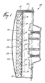
- the preferred embodiment of the traffic signal light in accordance with the present invention is generally identified by the reference 10.
- the traffic signal light 10 comprises an array 11 of light-emitting diodes such as 12.
- each column of diodes 12 are retained in the associated holes 13 by means of a flat diode-holding bar such as 15 ( Figure 1).
- Each bar 2 is made of plastic material and is formed with integral hollow deformable arrow-shaped fasteners such as 16 and integral arcuate convex deformable pressure-applying members such as 17.
- the board 14 is formed with rectangular holes such as 18 to receive the respective arrow-shaped fasteners 16.
- the diodes 12 of a column are first inserted in the respective holes 13 of the board 14 and then the arrow-shaped fasteners 16 of the diode-holding bar 15 are pushed into the respective holes 18.
- the hollow arrow-shaped fasteners 16 deform until the barbs 19 and 20 thereof are situated on the opposite side of the board 14.
- the arrow-shaped fasteners 16 then return to their original shape to thereby hook the bar 15 to the board 14.
- the arcuate, convex members 17 then apply pressure to the respective light-emitting diodes 12 to retain these diodes in the associated holes 13 of the board 14.
- the traffic signal light 10 also comprises an array 21 of prismatic toroidal nonimaging lenses such as 22 each associated with a corresponding one of the light-emitting diodes 12 for propagating the light rays from that associated diode 12.
- the array 21 of lenses 22 forms a one-piece prismatic plate preferably made of molded plastic material.
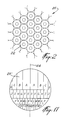
- the lenses 22 are disposed adjacent to each other in the array 21 in accordance with a honeycomb arrangement.
- the arrays 11 and 21 of light-emitting diodes 12 and lenses 22 are mounted into a housing 23 comprising a front wall 24 made of light-propagating material.
- the light-propagating material of the front wall 24 is red when the traffic signal light is a red traffic signal light.
- the front wall 24 defines a continuous, smooth outer surface 27. Surface 27 may be flat, or convex as illustrated in Figure 1. Of course, the continuous, smooth outer surface 27 will greatly facilitate cleaning of the traffic signal light 10.
- the design of the housing 23 is believed to be otherwise within the capacity of one of ordinary skill in the art and accordingly will not be further described.
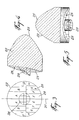
- Each lens 22 comprises a solid body of light-propagating material defining, on the side of the corresponding light-emitting diode 12, an inner light-refracting surface such as 25 ( Figures 1, 4 and 5) and, on the side opposite to the corresponding diode 12, an outer light-refracting surface such as 26 ( Figures 1, 3, 4 and 5).
- an inner light-refracting surface such as 25
- an outer light-refracting surface such as 26
- each lens 22 is generally parabolic to collimate the light rays such as 31 from the associated light-emitting diode 12 into a beam of parallel light rays such as 32 propagating though the solid body of the lens 22.
- Surface 25 therefore constitute a light-collimating surface.
- the outer light-refracting surface 26 of each lens 22 is formed of a central region 28 and an annular region 29 surrounding the central region 28. Because of the nature of the light emitting process that takes place within a light-emitting diode, the light density of the collimated beam (parallel light rays 32) produced by the light-refracting surface 25 is not constant radially. Therefore, as will be described in the following description, better results are achieved by dividing the light-refracting surface 26 of each lens 22 in two concentric areas (central region 28 and annular region 29) having an approximately constant light density.
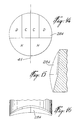
- the annular region 29 has a short radius concave cross section (Figure 5) lying in a horizontal plane and a long radius concave cross section (Figure 4) lying in a vertical plane. Also, each annular region 29 comprises an upper row and a lower row of light-refracting surface sections. More specifically, each annular region is divided into left upper light-refracting surface sections A-D, into right upper light-refracting surface sections A-D, into left lower light-refracting surface sections E-H, into right lower light-refracting surface sections E-H. As illustrated in Figure 3, the left light-refracting surface sections A-H are symmetrical with respect to the right light-refracting surface sections A-H about a vertical central plane 30. Each lens 22 is therefore a multiple section prismatic toroidal lens.
- each annular region 29 deviate the parallel light rays 32 propagating therethrough by refraction in view of forming a divergent light beam of larger horizontal dimension (see light rays 33 in Figure 7) and of smaller vertical dimension (see light rays 33 in Figure 6).
- the left and right light-refracting surface sections A-H of the annular region 29 are respectively associated to predetermined, distinct spatial regions and have different configurations (shape, orientation and position) in view of deviating the light rays 13 propagating through these left and right light-refracting surface sections A-V toward the corresponding spatial regions, respectively.
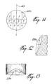
- Table 1 indicates that the left light-refracting surface section A should deviate the light rays 32 ( Figures 6 and 7) generated by the corresponding light-emitting diode 12 and propagating therethrough so that the deviated light rays such as 37 leaving the light-refracting surface section A will propagate in a direction defining with the central horizontal optical axis 35 ( Figures 6 and 7) of the lens 22, a vertical downward angle 36 ( Figure 6) of 2.5° and an horizontal left angle 38 ( Figure 7) of 2.5° toward a first spatial region (or spatial zone) 39 ( Figures 6 and 7) situated at a given distance from the light-refracting surface 26.
- Table 1 indicates that the right light-refracting surface section A deviates the light rays generated by the corresponding light-emitting diode 12 and propagating therethrough so that these light rays, when they leave the outer light-refracting surface 26 will propagate in a direction defining with the central horizontal optical axis 35 of the lens 22, a vertical downward angle of 2.5° and an horizontal right angle of 2.5° toward a second spatial region (or spatial zone) situated at the given distance from the light-refracting surface 26.
- Table 1 indicates that the left light-refracting surface section B deviates the light rays generated by the corresponding light-emitting diode 12 and propagating therethrough so that the light rays, when they leave the outer light-refracting surface 26 will propagate in a direction defining with the central horizontal optical axis 35 of the lens 22, a vertical downward angle of 2.5° and an horizontal left angle of 7.5° toward a third spatial region (or spatial zone) situated at the given distance from the light-refracting surface 26.
- Table 1 further indicates that the right light-refracting surface section B deviates the light rays generated by the corresponding light-emitting diode 12 and propagating therethrough so that these light rays, when they leave the outer light-refracting surface 26 will propagate in a direction defining with the central horizontal optical axis 35 of the lens 22, a vertical downward angle of 2.5° and an horizontal right angle of 7.5° toward a fourth spatial region situated at the given distance from the light-refracting surface 26.
- Table 1 is read in the same manner for the other left and right light-refracting surface sections C-H.
- the left and right light-refracting surface sections A-V have different dimensions to vary the light intensity at the different spatial regions in accordance with the unit candlepower values given in Table 1.
- the annular regions 29 of all the lenses 22 of the array 21 are identical whereby the light rays propagating through the left light-refracting surface sections A of all the lenses 22 are deviated toward a common spatial region 39 and add at this spatial region 39.
- the light rays propagating through each left and right light-refracting surface section A of all the lenses 22 are deviated toward a corresponding common spatial region and add at this spatial region. Therefore, the light intensity at each spatial region can be easily adjusted through the number of light-emitting diodes and associated lenses in the two arrays 11 and 21 in the proportion given by the relative dimensions of the light-refracting surface sections A-H, to thereby respect the Standard for Traffic Signal Lamps of the Institute of Transportation Engineers.
- central regions 28 of the outer light-refracting surfaces 26 of a given number of lenses 22 of the array 21 to increase the light intensity at the correspondinq spatial regions as required by the Standard for Traffic Signal Lamps of the Institute of Transportation Engineers.
- these central regions will be referred to as a first type of central regions 28d.
- each central region 28d is divided into left upper light-refracting surface sections C and D, right upper light-refracting surface sections C and D, a left lower light-refracting surface section H, and a right lower light-refracting surface section H.
- the left light-refracting surface sections C, D and H are symmetrical with respect to the right light-refracting surface sections C, D and H about a vertical central plane 41.
- the light-refracting surface sections C, D and H of the central regions 28d have different configurations (shape, orientation and position) in view of deviating the light rays 32 propagating therethrough toward the corresponding spatial regions, respectively (see for example light rays 40 of Figures 6 and 7) to thereby adjust as required the light intensity at these regions.
- Table 1 also indicates that other spatial regions (or spatial zones) I-V must also be illuminated to meet with the requirements of the Standard for Traffic Signal Lamps of the Institute of Transportation Engineers.
- the remaining central regions 28 of the lenses 22 of the array 21 are used for that purpose.
- each central regions 28b is divided into left upper light-refracting surface sections K-N, right upper light-refracting surface sections K-N, left lower light-refracting surface sections Q-T, and right lower light-refracting surface sections Q-T.
- the left light-refracting surface sections K-N and Q-T are symmetrical with respect to the right light-refracting surface sections K-N and Q-T about a vertical central plane 42.
- the light-refracting surface sections K-N and Q-T of the central regions 28b have different configurations (shape, orientation and position) in view of deviating the light rays 32 propagating therethrough toward the corresponding spatial regions, respectively.
- each central region 28c is divided into left upper light-refracting surface sections I and J, right upper light-refracting surface sections I and J, intermediate left light-refracting surface sections O and P, intermediate right light-refracting surface sections O and P, left lower light-refracting surface sections U and V, and right lower light-refracting surface sections U and V.
- the left light-refracting surface sections I, J, O, P, U and V are symmetrical with respect to the right light-refracting surface sections I, J, O, P, U and V about a vertical central plane 43.
- the light-refracting surface sections I, J, O, P, U and V of the central regions 28c have different configurations (shape, orientation and position) in view of deviating the light rays 32 propagating therethrough toward the corresponding spatial points, respectively.
- the left and right light-refracting surface sections K-V have different dimensions to vary the light intensity at the corresponding spatial points in accordance with the unit candlepower values given in Table 1, to thereby meet with the requirements of the Standard for Traffic Signal Lamps of the Institute of Transportation Engineers.
- the central region 28 of each lens is formed on the free end of a pin protruding from the annular region 29 ( Figures 1, 4, 5, 6 and 7).
- a lens can be called a double prismatic toroidal lens.
- the central regions 28b, 28c and 28d of each type are uniformly distributed over the lenses 22 of the array 21.
- the array 21 contains 320 lenses 22 and the central regions 28 include 38% of central regions 28b, 16% of central regions 28c and 46% of central regions 28d to meet with the requirements of the Standard for Traffic Signal Lamps of the Institute of Transportation Engineers (Table 1).
- each lens 22 may also be formed of a single surface 26' having both a long radius convex cross section lying in a vertical plane and a short radius concave cross section lying in a horizontal plane (see for example annular region 29 in Figures 3-5).
- Each outer light-refracting surface 26' of the lenses 22 is then divided into left light-refracting surface sections A-V, and into right light-refracting surface sections A-V.
- the left light-refracting surface sections A-V are symmetrical with respect to the right light-refracting surface sections A-V about a vertical central plane 44.
- Each lens 22 is therefore a multiple section prismatic toroidal lens.
- each light-refracting surface 26' is to deviate the light rays 32 ( Figures 6 and 7) by refraction in view of forming a divergent light beam of larger horizontal dimension and of smaller vertical dimension.
- the left and right light-refracting surface sections A-V of the light-refracting surface 26' of each lens 22 are respectively associated to the above defined predetermined, distinct spatial regions and have different configurations (shape, orientation and position) for deviating the light rays 32 propagating through these left and right light-refracting surface sections A-V toward the corresponding spatial regions, respectively.
- the left and right light-refracting surface sections A-V have different dimensions and positions to vary the light intensity at the different spatial regions in accordance with the unit candlepower values given in Table 1. More specifically, as illustrated in Figure 17, the left and right light-refracting surface sections A-V are arranged into horizontal rows of laterally adjacent light-refracting surface sections, the dimensions of the light-refracting surface sections generally reducing from an upper row to a lower row.
- each left and right light-refracting surface section A-V of the lenses 22 are deviated toward a corresponding common spatial region and add at this spatial region.
- the light intensity at each spatial region can therefore be easily adjusted through the number of light-emitting diodes and associated lenses in the two arrays 11 and 21 in the proportion given by the relative dimensions of the light refracting surface sections A-V, to thereby meet with the requirement of the Standard for Traffic Signal Lamps of the Institute of Transportation Engineers.
- a drawback of the embodiment of Figure 17 is that smaller surface sections have to be shaped to make manufacture of this embodiment more difficult.
- the surface sections of the different light-refracting surface can be approximated by a continuous concave surface.
Landscapes
- Engineering & Computer Science (AREA)
- General Engineering & Computer Science (AREA)
- Physics & Mathematics (AREA)
- General Physics & Mathematics (AREA)
- Optics & Photonics (AREA)
- Non-Portable Lighting Devices Or Systems Thereof (AREA)
- Traffic Control Systems (AREA)
Claims (20)
- Gerät zum Ausbreiten von Lichtstrahlen zu einer Mehrzahl von vorbestimmten verschiedenen Raumbereichen, mit einem Feld von Lichtquellen zum Erzeugen entsprechender Lichtstrahlen und einen Feld von Linsen, von denen jede mit einer entsprechenden der Lichtquellen verknüpft ist, worin(a) die Linsen jeweils einen festen Körper aus lichtausbreitenden Material aufweisen, das eine lichtbrechende Oberfläche definiert, durch die sich Lichtstrahlen von der entsprechenden Lichtquelle ausbreiten,(b) die lichtbrechende Oberfläche in lichtbrechende Oberflächenabschnitte unterteilt ist, von denen jeder mit einem entsprechenden der Raumbereiche verknüpft ist, und(c) die lichtbrechenden Oberflächenabschnitte verschiedene Konfigurationen in Hinblick auf das Ablenken der Lichtstrahlen aufweisen, die sich durch die lichtbrechenden Oberflächenabschnitte zu den entsprechenden Raumbereichen ausbreiten;
worin die Linsen eine Mehrzahl der mit jedem Raumbereich verknüpften lichtbrechenden Oberflächenabschnitte aufweist, wodurch sich die durch die Mehrzahl von lichtbrechenden Oberflächenabschnitte abgelenkten Lichtstrahlen an dem zugehörigen Raumbereich aufaddieren. - Gerät nach Anspruch 1, bei dem die lichtbrechende Oberfläche konkave Abschnitte mit einem kleinen Radius und einem großen Radius, die in entsprechenden im wesentlichen senkrechten Ebenen liegen, aufweist.
- Gerät nach Anspruch 2, bei dem die lichtbrechende Oberfläche sowohl prismatisch als auch torodial ist.
- Gerät nach Anspruch 1, bei dem die lichtbrechenden Oberflächenabschnitte unterschiedliche Abmessungen zum Einstellen der Lichtintensität an jedem Raumbereich aufweisen.
- Gerät nach Anspruch 1, bei dem der feste Körper auf der Seite der entsprechenden Lichtquelle eine Lichtsammeloberfläche zum Sammeln der Lichtstrahlen von der entsprechenden Lichtquelle definiert und bei dem die lichtbrechende Oberfläche auf der Seite des festen Körpers gegenüber der entsprechenden Lichtquelle angeordnet ist.
- Gerät nach Anspruch 5, bei dem die lichtsammelnde Oberfläche konvex ist und bei dem die lichtbrechende Oberfläche konkav ist.
- Gerät nach Anspruch 1, bei dem das Feld von Linsen ein einstückiges Feld ist, das aus gegossenen Kunststoffmaterial gemacht ist und bei dem die Linsen eine Honigwabenanordnung definieren.
- Gerät nach Anspruch 7, bei dem die lichtbrechende Oberfläche aus einem Mittelbereich und einem dem Mittelbereich umgebenden ringförmigen Bereich gebildet ist, wobei die lichtbrechenden Oberflächenabschnitte sowohl auf dem Mittelbereich als auch dem ringförmigen Bereich der lichtbrechenden Oberfläche verteilt sind.
- Gerät nach Anspruch 8, bei dem die ringförmigen Bereiche der lichtbrechenden Oberflächen der verschiedenen Linsen identisch sind, wobei die lichtbrechenden Oberflächen der Linsen verschiedene Arten von über das Feld von Linsen verteilten Mittelbereichen aufweisen.
- Gerät nach Anspruch 8, bei dem der Mittelbereich der lichtbrechenden Oberfläche einer jeden Linse von dem ringförmigen Bereich der gleichen lichtbrechenden Oberfläche vorsteht.
- Verkehrsampel mit:einem Feld von lichtemittierenden Dioden zum Erzeugen entsprechender Lichtstrahlen undeinem Feld von Linsen zum Ausbreiten von Lichtstrahlen von den lichtemittierenden Dioden zu einer Mehrzahl von vorbestimmten verschiedenen Raumbereichen, worin(a) die Linsen des Feldes jeweils mit einer entsprechenden der lichtemittierenden Dioden verknüpft sind,(b) die Linsen jeweils einen festen Körper aus lichtausbreitenden Material aufweisen, das eine lichtbrechende Oberfläche definiert, durch die sich die Lichtstrahlen von der entsprechenden lichtemittierenden Diode ausbreiten,(c) die lichtbrechende Oberfläche in lichtbrechende Oberflächenabschnitte unterteilt ist, die jeweils mit einem entsprechenden der Raumbereiche verknüpft sind, und(d) die lichtbrechenden Oberflächenabschnitte verschiedene Konfigurationen in Hinblick auf das Ablenken der Lichtstrahlen aufweisen, die sich durch die lichtbrechenden Oberflächenabschnitte zu den entsprechenden Raumbereichen ausbreiten;
worin die Linsen eine Mehrzahl der mit jedem Raumbereich verknüpften lichtbrechenden Oberflächenabschnitte aufweisen, wodurch sich die durch die Mehrzahl von lichtbrechenden Oberflächenabschnitte abgelenkten Lichtstrahlen an dem zugehörigen Raumbereich aufaddieren. - Verkehrsampel nach Anspruch 11, bei der die lichtbrechende Oberfläche einen konkaven Querschnitt kleinen Radius, der in einer allgemeinen horizontalen Ebene liegt, und einen konkaven Querschnitt großen Radius, der in einer im wesentlichen vertikalen Ebene liegt, aufweist.
- Verkehrsampel nach Anspruch 11, bei der die lichtbrechende Oberfläche sowohl prismatisch als auch torodial ist.
- Verkehrsampel nach Anspruch 11, bei der die lichtbrechenden Oberflächenabschnitte verschiedene Abmessungen zum Einstellen der Lichtintensität an jedem Raumbereich aufweisen.
- Verkehrsampel nach Anspruch 11, bei der der feste Körper auf der Seite der entsprechenden lichtemittierenden Diode eine lichtsammelnde Oberfläche zum Sammeln der Lichtstrahlen von der entsprechenden lichtemittierenden Diode definiert und bei der die lichtbrechende Oberfläche auf der Seite des festen Körpers gegenüber der entsprechenden lichtemittierenden Diode angeordnet ist.
- Verkehrsampel nach Anspruch 15, bei der die lichtsammelnde Oberfläche konvex und allgemein parabolisch ist und bei der die lichtbrechende Oberfläche konkav ist.
- Verkehrsampel nach Anspruch 11, bei der das Feld von Linsen ein einstückiges Feld ist, das aus gegossenen Kunststoffmaterial gemacht ist, und bei der die Linsen eine Honigwabenanordnung definieren.
- Verkehrsampel nach Anspruch 11, bei der die lichtbrechende Oberfläche aus einem Mittelbereich und einem den Mittelbereich umgebenden ringförmigen Bereich gebildet ist, wobei die lichtbrechenden Oberflächenabschnitte sowohl auf dem Mittelbereich als auch dem ringförmigen Bereich der lichtreflektierenden Oberflächen verteilt sind.
- Verkehrsampel nach Anspruch 18, wobei die ringförmigen Bereiche der lichtbrechenden Oberflächen der verschiedenen Linsen identisch sind und bei der die lichtbrechenden Oberflächen der Linsen verschiedene Arten von Mittelbereichen aufweisen, die über das Feld von Linsen verteilt sind.
- Verkehrsampel nach Anspruch 18, bei der der Mittelbereich der lichtbrechenden Oberfläche einer jeden Linse von dem ringförmigen Bereich der gleichen lichtbrechenden Oberfläche vorsteht.
Applications Claiming Priority (3)
| Application Number | Priority Date | Filing Date | Title |
|---|---|---|---|
| US386548 | 1989-07-27 | ||
| US08/386,548 US5636057A (en) | 1995-02-10 | 1995-02-10 | Prismatic toroidal lens and traffic signal light using this lens |
| PCT/CA1996/000068 WO1996024802A1 (en) | 1995-02-10 | 1996-02-02 | Prismatic toroidal lens and traffic signal light using this lens |
Publications (2)
| Publication Number | Publication Date |
|---|---|
| EP0808439A1 EP0808439A1 (de) | 1997-11-26 |
| EP0808439B1 true EP0808439B1 (de) | 1999-05-06 |
Family
ID=23526062
Family Applications (1)
| Application Number | Title | Priority Date | Filing Date |
|---|---|---|---|
| EP96900815A Expired - Lifetime EP0808439B1 (de) | 1995-02-10 | 1996-02-02 | Prismatische, toroidale linse und ein diese linse verwendendes verkehrssignallicht |
Country Status (5)
| Country | Link |
|---|---|
| US (1) | US5636057A (de) |
| EP (1) | EP0808439B1 (de) |
| AU (1) | AU4479596A (de) |
| DE (1) | DE69602352T2 (de) |
| WO (1) | WO1996024802A1 (de) |
Families Citing this family (57)
| Publication number | Priority date | Publication date | Assignee | Title |
|---|---|---|---|---|
| AU8876998A (en) * | 1997-09-04 | 1999-03-22 | Howells Railway Products Limited | Plural-led lights |
| US6570505B1 (en) | 1997-12-30 | 2003-05-27 | Gelcore Llc | LED lamp with a fault-indicating impedance-changing circuit |
| EP0935145A1 (de) * | 1998-02-04 | 1999-08-11 | IMS Industrial Micro System AG | Optische Signal- und Anzeigevorrichtung |
| RU2137978C1 (ru) * | 1998-03-26 | 1999-09-20 | Открытое акционерное общество "ЛОМО" | Осветительное устройство с несимметричным распределением светового потока относительно оптической оси |
| US6283613B1 (en) | 1999-07-29 | 2001-09-04 | Cooper Technologies Company | LED traffic light with individual LED reflectors |
| US6244727B1 (en) | 1999-09-27 | 2001-06-12 | American Signal Company | Optic lens cell and illuminated signage having a cell array |
| AT410711B (de) | 1999-10-08 | 2003-07-25 | Swarco Futurit Verkehrssignals | Signalgeberoptik mit led-reihen |
| RU2179280C2 (ru) * | 2000-03-10 | 2002-02-10 | Красноярский фонд "Конверсионный технопарк" | Светосигнальное устройство |
| US6443594B1 (en) * | 2000-03-31 | 2002-09-03 | Koninklijke Philips Electronics N.V. | One-piece lens arrays for collimating and focusing light and led light generators using same |
| US6323781B1 (en) * | 2000-08-22 | 2001-11-27 | Power Signal Technologies | Electronically steerable light output viewing angles for traffic signals |
| US6450662B1 (en) * | 2000-09-14 | 2002-09-17 | Power Signal Technology Inc. | Solid state traffic light apparatus having homogenous light source |
| US6439743B1 (en) * | 2000-10-05 | 2002-08-27 | Power Signal Technologies Inc. | Solid state traffic light apparatus having a cover including an integral lens |
| US6411045B1 (en) | 2000-12-14 | 2002-06-25 | General Electric Company | Light emitting diode power supply |
| US6509840B2 (en) * | 2001-01-10 | 2003-01-21 | Gelcore Llc | Sun phantom led traffic signal |
| US6773139B2 (en) * | 2001-09-17 | 2004-08-10 | Gelcore Llp | Variable optics spot module |
| AT414165B (de) * | 2001-10-09 | 2006-09-15 | Gifas Electric Ges M B H | Leuchte |
| DE10227753B3 (de) * | 2002-06-21 | 2004-01-22 | Stührenberg GmbH Elektrobau-Signaltechnik | Signalgeberoptik mit mehreren Lichtquellen |
| CA2391681A1 (en) * | 2002-06-26 | 2003-12-26 | Star Headlight & Lantern Co. Of Canada Ltd. | Solid-state warning light with microprocessor controlled excitation circuit |
| FR2863686B1 (fr) * | 2003-12-10 | 2006-02-24 | Sagem | Feu de signalisation a diodes electroluminescentes |
| US7207694B1 (en) * | 2004-08-20 | 2007-04-24 | Boyd Industries, Inc. | Light emitting diode operating and examination light system |
| US20060082999A1 (en) * | 2004-10-18 | 2006-04-20 | Klein W R | Refractive clamp/optic for light emitting diode |
| GB2421584A (en) * | 2004-12-21 | 2006-06-28 | Sharp Kk | Optical device with converging and diverging elements for directing light |
| EP1836071B1 (de) * | 2004-12-30 | 2013-06-12 | GE Lighting Solutions, LLC | Lichtsignalanlage mit einer gleichförmigen lichtfläche |
| WO2007065002A1 (en) * | 2005-12-03 | 2007-06-07 | Dongha Kim | High efficiency beam shaping illumination optical device for light emitting diode |
| WO2007100837A2 (en) | 2006-02-27 | 2007-09-07 | Illumination Management Solutions, Inc. | An improved led device for wide beam generation |
| US8434912B2 (en) | 2006-02-27 | 2013-05-07 | Illumination Management Solutions, Inc. | LED device for wide beam generation |
| CN103822172B (zh) * | 2007-04-05 | 2017-07-28 | 飞利浦灯具控股公司 | 光束成形器 |
| WO2008144672A1 (en) * | 2007-05-21 | 2008-11-27 | Illumination Management Solutions, Inc. | An improved led device for wide beam generation and method of making the same |
| CN101457901B (zh) * | 2007-12-14 | 2010-09-29 | 富士迈半导体精密工业(上海)有限公司 | 光场调节装置及采用该光场调节装置的照明装置 |
| US7972036B1 (en) | 2008-04-30 | 2011-07-05 | Genlyte Thomas Group Llc | Modular bollard luminaire louver |
| US7985004B1 (en) | 2008-04-30 | 2011-07-26 | Genlyte Thomas Group Llc | Luminaire |
| US7766509B1 (en) * | 2008-06-13 | 2010-08-03 | Lumec Inc. | Orientable lens for an LED fixture |
| US8002435B2 (en) * | 2008-06-13 | 2011-08-23 | Philips Electronics Ltd Philips Electronique Ltee | Orientable lens for an LED fixture |
| US7841750B2 (en) * | 2008-08-01 | 2010-11-30 | Ruud Lighting, Inc. | Light-directing lensing member with improved angled light distribution |
| MX2011001685A (es) | 2008-08-14 | 2011-08-17 | Cooper Technologies Co | Dispositivos de led para la generacion de dispersion amplia de haz. |
| US8231243B1 (en) | 2008-08-19 | 2012-07-31 | Philips Koninklijke Electronics N.V. | Vertical luminaire |
| WO2010065663A2 (en) * | 2008-12-03 | 2010-06-10 | Illumination Management Solutions, Inc. | An led replacement lamp and a method of replacing preexisting luminaires with led lighting assemblies |
| US8070328B1 (en) | 2009-01-13 | 2011-12-06 | Koninkliljke Philips Electronics N.V. | LED downlight |
| US8246212B2 (en) * | 2009-01-30 | 2012-08-21 | Koninklijke Philips Electronics N.V. | LED optical assembly |
| US9028097B2 (en) | 2009-10-30 | 2015-05-12 | Cree, Inc. | LED apparatus and method for accurate lens alignment |
| US9404634B2 (en) * | 2009-10-30 | 2016-08-02 | Cree, Inc. | LED light fixture with facilitated lensing alignment and method of manufacture |
| WO2011066421A2 (en) | 2009-11-25 | 2011-06-03 | Cooper Technologies Company | Systems, methods, and devices for sealing led light sources in a light module |
| US8388198B2 (en) | 2010-09-01 | 2013-03-05 | Illumination Management Solutions, Inc. | Device and apparatus for efficient collection and re-direction of emitted radiation |
| US9140430B2 (en) | 2011-02-28 | 2015-09-22 | Cooper Technologies Company | Method and system for managing light from a light emitting diode |
| EP2681484B1 (de) | 2011-02-28 | 2023-11-08 | Signify Holding B.V. | Verfahren und system zur verwaltung der lichtemission einer lichtemittierenden diode |
| US8585238B2 (en) | 2011-05-13 | 2013-11-19 | Lsi Industries, Inc. | Dual zone lighting apparatus |
| USD657087S1 (en) | 2011-05-13 | 2012-04-03 | Lsi Industries, Inc. | Lighting |
| GB2500726B (en) * | 2012-03-31 | 2014-06-11 | Graviton Lite Ltd | Security lighting apparatus |
| US8974077B2 (en) | 2012-07-30 | 2015-03-10 | Ultravision Technologies, Llc | Heat sink for LED light source |
| US9080739B1 (en) | 2012-09-14 | 2015-07-14 | Cooper Technologies Company | System for producing a slender illumination pattern from a light emitting diode |
| US9200765B1 (en) | 2012-11-20 | 2015-12-01 | Cooper Technologies Company | Method and system for redirecting light emitted from a light emitting diode |
| US9732936B2 (en) | 2014-01-21 | 2017-08-15 | Bridgelux Inc. | Optics for chip-on-board road and area lighting |
| US9816682B2 (en) | 2014-04-02 | 2017-11-14 | Bridgelux Inc. | Optics for chip-on-board lighting having a protrusion |
| EP3326017A1 (de) * | 2015-07-22 | 2018-05-30 | Adolf Nissen Elektrobau GmbH + Co.KG | Optische baugruppe eines wechselverkehrszeichens und wechselverkehrszeichen |
| CN110047287B (zh) * | 2019-04-23 | 2021-04-02 | 临沂大学 | 一种道路状况提示方法及其装置 |
| CZ308678B6 (cs) * | 2020-03-06 | 2021-02-10 | Ústav Fyziky Plazmatu Av Čr, V. V. I. | Sestava optického prvku |
| DE102024110253A1 (de) * | 2024-04-12 | 2025-10-16 | Bremicker Verkehrstechnik Gmbh | Lichtleitelement für Anzeigetafeln |
Family Cites Families (12)
| Publication number | Priority date | Publication date | Assignee | Title |
|---|---|---|---|---|
| DE8504325U1 (de) * | 1985-02-13 | 1985-07-04 | Semperlux Gmbh, 1000 Berlin | Einrichtung zum Entblenden von großflächigen Leuchtmitteln |
| US4862330A (en) * | 1987-09-21 | 1989-08-29 | Koito Manufacturing Co., Ltd. | Vehicle lamp |
| JP2572626B2 (ja) * | 1988-04-28 | 1997-01-16 | 旭光学工業株式会社 | 焦点板及び微細構造配列体の形成方法 |
| JP2568434B2 (ja) * | 1989-01-06 | 1997-01-08 | シャープ株式会社 | 画像読取装置 |
| US5148322A (en) * | 1989-11-09 | 1992-09-15 | Omron Tateisi Electronics Co. | Micro aspherical lens and fabricating method therefor and optical device |
| US5119235A (en) * | 1989-12-21 | 1992-06-02 | Nikon Corporation | Focusing screen and method of manufacturing same |
| JPH0777081B2 (ja) * | 1990-03-26 | 1995-08-16 | 株式会社ゼニライトブイ | 灯ろうおよび灯ろう用レンズ |
| US5139609A (en) * | 1991-02-11 | 1992-08-18 | The Aerospace Corporation | Apparatus and method for longitudinal diode bar pumping of solid state lasers |
| US5174649B1 (en) * | 1991-07-17 | 1998-04-14 | Precision Solar Controls Inc | Led lamp including refractive lens element |
| CA2078839A1 (en) * | 1991-09-25 | 1993-03-26 | Marc Hoffman | Double refraction and total reflection solid nonimaging lens |
| JP3147481B2 (ja) * | 1992-04-21 | 2001-03-19 | 松下電器産業株式会社 | ガラス製回折格子の成形用金型及びその製造方法及びガラス製回折格子の製造方法 |
| FR2707223B1 (fr) * | 1993-07-07 | 1995-09-29 | Valeo Vision | Feu de signalisation perfectionné à diodes électroluminescentes. |
-
1995
- 1995-02-10 US US08/386,548 patent/US5636057A/en not_active Expired - Lifetime
-
1996
- 1996-02-02 DE DE69602352T patent/DE69602352T2/de not_active Expired - Fee Related
- 1996-02-02 EP EP96900815A patent/EP0808439B1/de not_active Expired - Lifetime
- 1996-02-02 WO PCT/CA1996/000068 patent/WO1996024802A1/en not_active Ceased
- 1996-02-02 AU AU44795/96A patent/AU4479596A/en not_active Abandoned
Also Published As
| Publication number | Publication date |
|---|---|
| US5636057A (en) | 1997-06-03 |
| AU4479596A (en) | 1996-08-27 |
| DE69602352T2 (de) | 1999-10-07 |
| DE69602352D1 (de) | 1999-06-10 |
| WO1996024802A1 (en) | 1996-08-15 |
| EP0808439A1 (de) | 1997-11-26 |
Similar Documents
| Publication | Publication Date | Title |
|---|---|---|
| EP0808439B1 (de) | Prismatische, toroidale linse und ein diese linse verwendendes verkehrssignallicht | |
| US7083313B2 (en) | Side-emitting collimator | |
| US7520650B2 (en) | Side-emitting collimator | |
| EP2334980B1 (de) | Kompaktes optisches system und linsen zur erzeugung von gleichförmigem kollimiertem licht | |
| US7918583B2 (en) | Illumination devices | |
| US5592578A (en) | Peripheral optical element for redirecting light from an LED | |
| US8061883B2 (en) | Illuminating devices using small PT sources including LEDs | |
| US9285098B2 (en) | LED luminaire | |
| US6948832B2 (en) | Luminaire device | |
| US7441929B2 (en) | Lighting unit having a plurality of curved surface elements | |
| US9689554B1 (en) | Asymmetric area lighting lens | |
| KR20190040269A (ko) | 적어도 2개의 광 분배들을 발생시키기 위한 자동차 헤드라이트용 조명 유닛 | |
| US20110170291A1 (en) | Efficient and uniformly distributed illumination from multiple source luminairies | |
| EP3449179B1 (de) | Mehrstrahliges fahrzeuglicht | |
| US6361191B1 (en) | Off-axis and segment collimation and projection | |
| US7677760B2 (en) | Efficient and uniformly distributed illumination from multiple source luminaires | |
| KR100733110B1 (ko) | 에지-발광되는 도파관 및 빛을 추출하고 배향하는 부재를별개로 갖는 발광 시스템 | |
| US6354725B1 (en) | Broad architectural illumination from expanded and remote light distribution optics of luminaires | |
| US20160363711A1 (en) | Lighting system with improved illumination distribution and output luminance variation | |
| US4538216A (en) | Lighting apparatus | |
| US8746936B2 (en) | Luminaire and optical component | |
| US7123419B1 (en) | Collimating and optical elements with reduced mass | |
| US10871271B2 (en) | Diverging TIR facet LED optics producing narrow beams with color consistency | |
| CN214790664U (zh) | 照明装置 | |
| US20210003266A1 (en) | An optical device for modifying light distribution |
Legal Events
| Date | Code | Title | Description |
|---|---|---|---|
| PUAI | Public reference made under article 153(3) epc to a published international application that has entered the european phase |
Free format text: ORIGINAL CODE: 0009012 |
|
| 17P | Request for examination filed |
Effective date: 19970808 |
|
| AK | Designated contracting states |
Kind code of ref document: A1 Designated state(s): DE FR GB NL SE |
|
| 17Q | First examination report despatched |
Effective date: 19971121 |
|
| GRAG | Despatch of communication of intention to grant |
Free format text: ORIGINAL CODE: EPIDOS AGRA |
|
| GRAG | Despatch of communication of intention to grant |
Free format text: ORIGINAL CODE: EPIDOS AGRA |
|
| GRAG | Despatch of communication of intention to grant |
Free format text: ORIGINAL CODE: EPIDOS AGRA |
|
| GRAH | Despatch of communication of intention to grant a patent |
Free format text: ORIGINAL CODE: EPIDOS IGRA |
|
| GRAH | Despatch of communication of intention to grant a patent |
Free format text: ORIGINAL CODE: EPIDOS IGRA |
|
| GRAA | (expected) grant |
Free format text: ORIGINAL CODE: 0009210 |
|
| AK | Designated contracting states |
Kind code of ref document: B1 Designated state(s): DE FR GB NL SE |
|
| ET | Fr: translation filed | ||
| REF | Corresponds to: |
Ref document number: 69602352 Country of ref document: DE Date of ref document: 19990610 |
|
| PLBE | No opposition filed within time limit |
Free format text: ORIGINAL CODE: 0009261 |
|
| STAA | Information on the status of an ep patent application or granted ep patent |
Free format text: STATUS: NO OPPOSITION FILED WITHIN TIME LIMIT |
|
| 26N | No opposition filed | ||
| NLS | Nl: assignments of ep-patents |
Owner name: GELCORE, LLC |
|
| REG | Reference to a national code |
Ref country code: GB Ref legal event code: 732E |
|
| REG | Reference to a national code |
Ref country code: GB Ref legal event code: IF02 |
|
| PGFP | Annual fee paid to national office [announced via postgrant information from national office to epo] |
Ref country code: SE Payment date: 20080227 Year of fee payment: 13 Ref country code: NL Payment date: 20080224 Year of fee payment: 13 Ref country code: GB Payment date: 20080227 Year of fee payment: 13 |
|
| PGFP | Annual fee paid to national office [announced via postgrant information from national office to epo] |
Ref country code: FR Payment date: 20080218 Year of fee payment: 13 Ref country code: DE Payment date: 20080331 Year of fee payment: 13 |
|
| EUG | Se: european patent has lapsed | ||
| GBPC | Gb: european patent ceased through non-payment of renewal fee |
Effective date: 20090202 |
|
| NLV4 | Nl: lapsed or anulled due to non-payment of the annual fee |
Effective date: 20090901 |
|
| REG | Reference to a national code |
Ref country code: FR Ref legal event code: ST Effective date: 20091030 |
|
| PG25 | Lapsed in a contracting state [announced via postgrant information from national office to epo] |
Ref country code: NL Free format text: LAPSE BECAUSE OF NON-PAYMENT OF DUE FEES Effective date: 20090901 |
|
| PG25 | Lapsed in a contracting state [announced via postgrant information from national office to epo] |
Ref country code: DE Free format text: LAPSE BECAUSE OF NON-PAYMENT OF DUE FEES Effective date: 20090901 |
|
| PG25 | Lapsed in a contracting state [announced via postgrant information from national office to epo] |
Ref country code: GB Free format text: LAPSE BECAUSE OF NON-PAYMENT OF DUE FEES Effective date: 20090202 Ref country code: FR Free format text: LAPSE BECAUSE OF NON-PAYMENT OF DUE FEES Effective date: 20090302 |
|
| PG25 | Lapsed in a contracting state [announced via postgrant information from national office to epo] |
Ref country code: SE Free format text: LAPSE BECAUSE OF NON-PAYMENT OF DUE FEES Effective date: 20090203 |