EP0808034A2 - Method and apparatus for handover control in a satellite based telecommunications system - Google Patents
Method and apparatus for handover control in a satellite based telecommunications system Download PDFInfo
- Publication number
- EP0808034A2 EP0808034A2 EP97107785A EP97107785A EP0808034A2 EP 0808034 A2 EP0808034 A2 EP 0808034A2 EP 97107785 A EP97107785 A EP 97107785A EP 97107785 A EP97107785 A EP 97107785A EP 0808034 A2 EP0808034 A2 EP 0808034A2
- Authority
- EP
- European Patent Office
- Prior art keywords
- channel
- mobile station
- handover
- over
- time
- Prior art date
- Legal status (The legal status is an assumption and is not a legal conclusion. Google has not performed a legal analysis and makes no representation as to the accuracy of the status listed.)
- Granted
Links
Images


Classifications
-
- H—ELECTRICITY
- H04—ELECTRIC COMMUNICATION TECHNIQUE
- H04B—TRANSMISSION
- H04B7/00—Radio transmission systems, i.e. using radiation field
- H04B7/14—Relay systems
- H04B7/15—Active relay systems
- H04B7/185—Space-based or airborne stations; Stations for satellite systems
- H04B7/1853—Satellite systems for providing telephony service to a mobile station, i.e. mobile satellite service
- H04B7/18539—Arrangements for managing radio, resources, i.e. for establishing or releasing a connection
- H04B7/18541—Arrangements for managing radio, resources, i.e. for establishing or releasing a connection for handover of resources
-
- H—ELECTRICITY
- H04—ELECTRIC COMMUNICATION TECHNIQUE
- H04W—WIRELESS COMMUNICATION NETWORKS
- H04W36/00—Hand-off or reselection arrangements
- H04W36/0005—Control or signalling for completing the hand-off
- H04W36/0083—Determination of parameters used for hand-off, e.g. generation or modification of neighbour cell lists
- H04W36/0085—Hand-off measurements
-
- H—ELECTRICITY
- H04—ELECTRIC COMMUNICATION TECHNIQUE
- H04W—WIRELESS COMMUNICATION NETWORKS
- H04W36/00—Hand-off or reselection arrangements
- H04W36/0005—Control or signalling for completing the hand-off
- H04W36/0083—Determination of parameters used for hand-off, e.g. generation or modification of neighbour cell lists
- H04W36/00837—Determination of triggering parameters for hand-off
-
- H—ELECTRICITY
- H04—ELECTRIC COMMUNICATION TECHNIQUE
- H04W—WIRELESS COMMUNICATION NETWORKS
- H04W36/00—Hand-off or reselection arrangements
- H04W36/06—Reselecting a communication resource in the serving access point
-
- H—ELECTRICITY
- H04—ELECTRIC COMMUNICATION TECHNIQUE
- H04W—WIRELESS COMMUNICATION NETWORKS
- H04W48/00—Access restriction; Network selection; Access point selection
- H04W48/08—Access restriction or access information delivery, e.g. discovery data delivery
-
- H—ELECTRICITY
- H04—ELECTRIC COMMUNICATION TECHNIQUE
- H04W—WIRELESS COMMUNICATION NETWORKS
- H04W76/00—Connection management
- H04W76/10—Connection setup
-
- H—ELECTRICITY
- H04—ELECTRIC COMMUNICATION TECHNIQUE
- H04W—WIRELESS COMMUNICATION NETWORKS
- H04W84/00—Network topologies
- H04W84/02—Hierarchically pre-organised networks, e.g. paging networks, cellular networks, WLAN [Wireless Local Area Network] or WLL [Wireless Local Loop]
- H04W84/04—Large scale networks; Deep hierarchical networks
- H04W84/06—Airborne or Satellite Networks
-
- H—ELECTRICITY
- H04—ELECTRIC COMMUNICATION TECHNIQUE
- H04W—WIRELESS COMMUNICATION NETWORKS
- H04W88/00—Devices specially adapted for wireless communication networks, e.g. terminals, base stations or access point devices
- H04W88/12—Access point controller devices
Definitions
- the present invention generally relates to a satellite based telecommunications system and, more specifically, to a control process whereby the mobile and base stations effect seamless handovers between communications channels as mobile stations pass between satellite coverage beams.
- the ODYSSEY system proposes a satellite based telecommunications system in which a constellation of telecommunications satellites orbits the earth. The satellites relay communications between the mobile and ground stations (the terms ground stations and based stations are used interchangeable hereafter). Each satellite defines a plurality of communications beams which cooperate to form a coverage area of the earth. The coverage area moves relative to the earth's surface as the satellite orbits the earth.
- a mobile station communicates with an overhead satellite while in its associated coverage area. The overhead satellite in turn relays the communications to and from a corresponding ground station also within the satellite's coverage area.
- each subsection represents a fixed predefined geographic "cell" upon the surface of the earth.
- each subsection corresponds to a coverage beam which defines a dynamic geographic area which moves across the surface of the earth as the satellite orbits the earth.
- Each cell or beam in a coverage area is assigned a unique frequency as a carrier for all communications.
- Each carrier frequency supports multiple channels, with each channel being assigned to a specific mobile station located in the corresponding beam or cell.
- a mobile station communicates with the ground station at the assigned frequency and on an assigned communications channel so long as the mobile station is within the associated beam/cell.
- the mobile station when the mobile station leaves an old beam/cell and enters a new one, the mobile station must be assigned to a new communications channel. Also, the mobile station must adjust its communications frequency to the frequency associated with the new cell. Otherwise, the communications channel (and an ongoing call) will be dropped (i.e., disconnected). Once in the new beam/cell, the mobile station will use the new channel for all communications with the ground station.
- Handovers are necessary when a mobile station physically moves from one beam or cell to another. Additionally, in satellite based systems, handovers are necessary when the relative motion of the satellite, with respect to a mobile station, causes a corresponding coverage beam spot to pass over the mobile station which may or may not be stationary. To effect a handover, the mobile station must switch to a new transmitter or uplink frequency determined by the ground station. In addition, the ground station must "acquire" the mobile station's new uplink frequency (i.e. establish a communications link at the new frequency). The ground station must also switch the handed over call in the network (i.e., continue transmitting the communications or conversation at the new frequency). Handovers may occur in the middle of a call while conversation is being passed to and from the mobile station.
- ground station determines that a handover is necessary, the ground station sends an appropriate command to the mobile station. This command directs the mobile station to immediately switch to the new channel and new frequency without delay. Upon receiving the command, the mobile station switches, and begins to transmit over, the new channel and at the new frequency. The ground station continues to communicate over the old channel but monitors the new channel. Once the ground station detects incoming communications over the new channel, the ground station begins transmitting outgoing communications over the new channel.
- unscheduled handovers may produce interrupts or interference in a communications link which may be detected as breaks or "clicks" by the parties to a conversation.
- Such interrupts and interference result when handovers occur in the middle of a telephone conversation while the new channel is established.
- Conversations are carried over assigned channels as a stream of frames of communications data.
- the stream of communications data is rerouted from the old channel to the new channel.
- the interruption in the stream of data produces the clicks or breaks in conversation.
- the magnitude of an interrupt is dependent in part on a "round trip delay time" between the ground and mobile stations (i.e., the time period necessary for a frame of communications data to travel from the ground station to the mobile station and back to the ground station).
- Such interrupts are not overly disruptive in GSM systems since the round trip delay time is relatively short (e.g., 120 microseconds or less).
- satellite based systems may experience significantly longer round trip delay times.
- a frame of communications data must travel from a ground station to a satellite, to a mobile station, back to the satellite and back to the ground station.
- the round trip delay time may be approximately 192 milliseconds.
- the interrupts during unscheduled handovers have a significantly greater detrimental effect on calls in satellite based telecommunications systems.
- satellite based systems may require more than one frame of communications data to be passed between the ground station and mobile station during the process of establishing a new channel.
- the handover process may extend over a time period which is greater than one round trip delay time, thereby further exaggerating the detrimentally effects of the unscheduled handover process.
- a method and apparatus are provided for controlling mobile and base stations (14 and 16) during satellite (12) based telecommunications to perform scheduled handovers between two communications channels (26 and 27).
- the base station (16) determines when a handover will be necessary. Once determined, the base station (16) generates a handover scheduling command (node #4) which includes a scheduled handover time representing a time in the future at which the handover will occur.
- the handover scheduling command is transmitted over the first channel to the mobile station (14).
- the mobile station (14) Upon receipt of the handover scheduling command, performs steps necessary to establish a second communications link over a second channel (27), prior to the scheduled handover time.
- the mobile and base stations (14 and 16) At the scheduled handover time (node #21), the mobile and base stations (14 and 16) have established the second communications link on the second channel (27). To establish the second channel the mobile station calculations of the second channels frequency, timing offset and power level (node #11). By using a scheduled handover process, the mobile and base stations (14 and 16) avoid the production of interference and breaks within a conversation transmitted therebetween.
- Fig. 1 generally illustrates a satellite based telecommunications system 10 which includes a satellite 12, at least one mobile station (MS) 14 and at least one base or ground station (BS or GS) 16.
- the satellite 12 emits a plurality of coverage beams 18 which cooperate to define a coverage area 20.
- the mobile station 14 is located in coverage beam 22 and the base station 16 is located in coverage beam 24.
- the mobile station 14 communicates with the base station 16 via the satellite 12.
- the system 10 may utilize time division multiple access (TDMA), code division multiple access (CDMA) and similar techniques to increase the overall capacity.
- TDMA time division multiple access
- CDMA code division multiple access
- the mobile station 14 transmits and receives frames of communications data to and from the satellite 12 over an assigned communications channel (generally denoted by reference numeral 26).
- the uplink communications channel has a carrier frequency corresponding to that of the coverage beam 22.
- the satellite 12 in turn relays the frames of communications data to and from the base station 16 along the same channel 26 at a frequency corresponding to coverage area 24.
- a new communications channel must be assigned to the mobile station 14 and a new communications link must be established. This assignment process is referred to as a handover. A scheduled handover process is explained in more detail below.
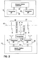
- Fig. 2 illustrates a block diagram of a mobile station 14 and a base station 16.
- the mobile station may include two transceivers 30 and 32 and a transmitter 33 which are controlled by a controller 34.
- a switch 35 selectively connects one of transceivers to the transmitter 33.
- the base station 16 also includes multiple transceivers 36 and 38 which are controlled by a controller 40.
- the block diagram in Fig. 2 merely is illustrative of the fact that the base station and the mobile station are capable of communicating with one another over two separate channels 26 and 27. While the transceivers 30 and 32 may simultaneously receive signals over channels 26 and 27, it is understood that the transmitter 33 only transmits over one of channels 26 and 27 at any given instant. Switch 35 selects the output channel.
- the path in channel 27 from the transmitter 33 has been represented in dashed lines to illustrate that the transmitter 33 alternately outputs signals over channels 26 and 27.
- the mobile and base stations 14 and 16 need not necessarily include two physically separate receivers and transmitters. Any conventional devices may be combined in place of the first and second transceivers so long as the mobile and base stations 14 and 16 are capable of simultaneous communication over two channels.
- the base station 16 is capable of communicating over multiple channels with multiple mobile stations.
- the dashed line 42 is illustrative of the satellite 12 which functions as a "bent pipe" and simply retransmits frames of communications data received from the mobile station and base station.
- a handover is performed to transfer a communications link between a base station and mobile station from a first channel 26 (Fig. 2) to a second channel 27.
- the flow diagram of Fig. 3 illustrates a plurality of vertical layers denoted by lines 42-52.
- Layer 42 corresponds to functions performed by the mobile station controller 34
- layers 44 and 46 correspond to the first and second transceivers 30 and 32 within the mobile station 14.
- Layers 48 and 50 correspond to the first and second transceivers 36 and 38 used within the base station 16.
- Layer 54 corresponds to functions performed by the controller 40 in the base station 16.
- the circles within each of layers 42-52 represent nodes at which frames are received/transmitted and at which functions are performed to effect a handover.
- the arrows between layers 44 and 48 represent command and communications data passed between the mobile and base stations 14 and 16 through the first communications links over the first channel 26 (Fig. 2).
- the arrows between layers 46 and 50 represent command and communications data passed via the second communications link over the second channel 27.
- Fig. 3 merely illustrates the functions involved in a handover. It is assumed that, at node #1, a communications link has already been established over a first channel 26 (corresponding to coverage beam 22). It is further assumed that a call is in progress and frames of communications data (e.g., conversation) is being passed between the parties. At node #1, a second channel 27 has not yet been established. To "establish" a channel, channel parameters must be synchronized between the mobile and base stations for the particular channel. The channel parameters may include a timing offset, frequency, a power level, CDMA coding, encryption coding and the like. These telemetry parameters are explained in more detail in a book entitled "An Introduction to GSM,” by Siegmund M. Redl, published by Artech House Publishers, Boston, MA, (1995), which is incorporated herein by reference.
- the mobile station 14 generates a report which is transmitted to the base station 16 over the first channel 26.
- the report may include telemetry information regarding the status of and environment surrounding the mobile station 14.
- the telemetry information may include the power level of the present communications link 26 with the satellite 12.
- the telemetry information may also include frequencies of signals detected by the mobile station 14 from neighboring coverage beams, along with the power levels of these detected signals.
- the telemetry information may include the frequencies and power levels of signals corresponding to coverage beams 60-64.
- the report would include telemetry information indicating an increase in the power level of incoming signals at the frequency associated with coverage beam 64.
- the controller 40 analyzes the report at node #4. During this analysis, the controller 40 determines whether the mobile station 14 is about to leave the current coverage beam 22 (node #4). This determination may be performed in one of several ways. For instance, the base station 16 may analyze the power level, within the report, of the current channel 26 detected by the mobile station 14. If the power level of the current channel 26 falls below a minimum threshold, the controller 40 may determine that this power loss is due to the fact that the mobile station is moving out of the coverage beam 22. Hence, if the power level of the current channel falls below the threshold, the controller 40 may determine that a handover will be necessary in the near future.
- the controller may independently determine that a handover is necessary by continuously monitoring the position of the mobile station 14 and the position of the associated coverage beam 22.
- the above identified co-pending application which is assigned to the assignee of the present application and which is incorporated herein by reference describes such a system.
- This co-pending application describes a system whereby the controller of the ground station continuously monitors the GEO position of the mobile stations and of the corresponding coverage beams. Based on monitoring of the GEO position, the ground station independently determines that the mobile station 14 is approaching a boundary of the coverage beam 22. Thus, the base station 16 independently determines that a handover will be necessary in the near future. Responsive thereto, the ground station initiates the handover process at node #4 (Fig. 3).
- the handover process is initiated at node #4 (Fig. 3) independent of any information received from the mobile station 14. Accordingly, it should be noted that the preferred embodiment may omit the report generated at node #1.
- the base station 16 determines that a handover is necessary, it generates a handover command which is transmitted between nodes #5 and #6 upon channel #1 (26 in Fig. 2) to the mobile station 14.
- the handover command includes all information necessary for the mobile station 14 to schedule or "script" a handover including a scheduled handover time.
- the handover command also includes
- the mobile station 14 transmits consecutive frames of communications data (denoted frame 1, frame 2 and frame 3).
- the scheduled handover time may be set to coincide with the end of frame 2 and the beginning of frame 3. Hence, the handover would occur after frame 2 has been transmitted on channel #1 (26 in Fig. 2) and prior to transmission of frame 3 which will be transmitted on Channel #2.
- the scheduled handover time is set sufficiently far in the future to afford time for the base and mobile stations to prepare for the handover as explained hereinafter (e.g., 2 or 3 seconds after the base station 16 determines that a handover is necessary at node #4 and transmits the handover command at node #5).
- the estimated new channel parameters identify the new channel 27 upon which the mobile station will communicate while located in the new coverage beam.
- the channel parameters include an estimated frequency, timing offset and power level corresponding to the new channel to be utilized in the new coverage beam.
- the timing offset is utilized to synchronize the mobile station with respect to the base station. A timing offset may be necessary since mobile stations and ground stations may be found at different distances from the satellite. Depending upon these distances, the delay time and the attenuation of an individual mobile station's signal is likely to be different from the delay and attenuation of any other mobile station's signal. In order to assure proper timing of transmissions from a mobile station, as well as proper reception, a timing delay or offset is measured for each mobile station. The timing offset governs the time at which the mobile station transmits frames of communications data in order to assure that the frames arrive at the ground station at the proper time.
- the mobile stations are adjusted to transmit at different power levels.
- the power level control signal governs the power at which frames of communications data are transmitted from the mobile stations.
- the ground station estimates at node #4 the channel parameters including the new frequency, new timing offset and new power level for the new channel. However, the signals are simply estimates which must be corrected by the mobile station.
- the handover command may include any necessary secondary information, such as any new CDMA and enscription codes to be used with the new channel.
- the handover command is received over channel #1 of the mobile station and deciphered by the controller 34 (node #7). Once the mobile station controller 34 determines that a handover has been scheduled to occur at a fixed time in the future, the mobile station records the scheduled handover time. In addition, the mobile station establishes channel #2 at the estimated new frequency, with the estimated timing offset and estimated power level. Thereafter, the mobile station controller 34 monitors channel #2.
- the base station 16 transmits the handover command it subsequently transmits an establishment signal over channel #2 (node #8) at the estimated new frequency.
- the establishment signal is received (node #9) over channel #2 (27 in Fig. 2) and analyzed by the mobile station controller 34 (node #10).
- the mobile station controller 34 calculates the actual or correct channel parameters for the timing offset, power level and new frequency for channel #2 based on the received establishment signal.
- the mobile station controller 34 determines the difference between the estimated and actual/corrected channel parameters. These differences represent offset errors. Once the corrected frequency offset, timing offset and power level are calculated by the mobile station 14, the mobile station reports the offset errors to the base station 16.
- the offset errors in frequency, power and timing are transmitted as channel #2 parameters at node #12 over channel #1 to the ground station.
- the corrected frequency, timing offset and power level may be transmitted.
- the base station 16 Upon receiving the offset errors at node #13, the base station 16 corrects the estimated frequency, power level and timing offset parameters for the new channel. Thereafter the corrected frequency, power level and timing offset parameters are relayed (node #15) over channel #1 back to the mobile station. In this manner, ground stations then obtain the parameters for frequency, timing offset and power level to establish and synchronize a communications link over the new channel #2 for use with the new coverage beam.
- the mobile station 14 continues to transmit frames of communications data over channel #1 (node #18) to the base station 16 until the scheduled handoff time occurs. Once the scheduled handoff time occurs (node #21 in Fig. 3), the mobile station automatically begins to transmit frames of communications data over channel #2 (node #22) to the base station 16.
- the scheduled handoff time occurs between frames 2 and 3.
- frames 1 and 2 are transmitted over channel #1 (via nodes #18 and #19).
- Frame 3 is then transmitted over channel #2 (via nodes #22 and #23).
- the base station 16 transmits a release command over channel #2 (via nodes #25 and #26) to direct the mobile station 14 to release channel #1.
- This process is repeated each time the mobile station 14 passes between two coverage beams.
- the inventive process provides a scheduled handover procedure which avoids the interrupts and interference caused by long propagation delays in the convention unscheduled handover technique since the handover occurs after the new channel is established.
- the inventive scheduled handover procedure also speeds the acquisition process of the new channel and the switching process between channels since both channels are used during establishment of the new channel and while the new channel's parameters are calculated. Switching occurs simultaneously and instantaneously at the scheduled handover time.
- the scheduled handover time is set sufficiently far in the future after the base station determines that a handover is necessary to afford adequate time to establish a second channel and to pre-coordinate channel parameters such as timing, power and frequency.
Landscapes
- Engineering & Computer Science (AREA)
- Computer Networks & Wireless Communication (AREA)
- Signal Processing (AREA)
- Physics & Mathematics (AREA)
- Astronomy & Astrophysics (AREA)
- Aviation & Aerospace Engineering (AREA)
- General Physics & Mathematics (AREA)
- Mobile Radio Communication Systems (AREA)
- Radio Relay Systems (AREA)
- Radio Transmission System (AREA)
Abstract
Description
- The present invention generally relates to a satellite based telecommunications system and, more specifically, to a control process whereby the mobile and base stations effect seamless handovers between communications channels as mobile stations pass between satellite coverage beams.
- In recent years, several forms of mobile communications systems have been proposed, such as the GSM system offered in Europe and the ODYSSEY system proposed by the assignee of the present application. These systems offer mobile telecommunications between ground or based stations and mobile stations, such as cellular telephones and the like. In the GSM system, the ground stations communicate directly with any mobile stations located within the ground stations coverage area. The ODYSSEY system proposes a satellite based telecommunications system in which a constellation of telecommunications satellites orbits the earth. The satellites relay communications between the mobile and ground stations (the terms ground stations and based stations are used interchangeable hereafter). Each satellite defines a plurality of communications beams which cooperate to form a coverage area of the earth. The coverage area moves relative to the earth's surface as the satellite orbits the earth. A mobile station communicates with an overhead satellite while in its associated coverage area. The overhead satellite in turn relays the communications to and from a corresponding ground station also within the satellite's coverage area.
- The coverage areas are divided into subsections, both in the GSM system and in satellite based systems. By dividing the coverage area into subsections, the system increases the number of available communications channels and thus the overall capacity (i.e., the number of mobile stations which may be supported by the system). In the GSM system, each subsection represents a fixed predefined geographic "cell" upon the surface of the earth. In satellite based systems, each subsection corresponds to a coverage beam which defines a dynamic geographic area which moves across the surface of the earth as the satellite orbits the earth. Each cell or beam in a coverage area is assigned a unique frequency as a carrier for all communications. Each carrier frequency supports multiple channels, with each channel being assigned to a specific mobile station located in the corresponding beam or cell. A mobile station communicates with the ground station at the assigned frequency and on an assigned communications channel so long as the mobile station is within the associated beam/cell.
- However, when the mobile station leaves an old beam/cell and enters a new one, the mobile station must be assigned to a new communications channel. Also, the mobile station must adjust its communications frequency to the frequency associated with the new cell. Otherwise, the communications channel (and an ongoing call) will be dropped (i.e., disconnected). Once in the new beam/cell, the mobile station will use the new channel for all communications with the ground station.
- The process of switching channels is referred to as a "handover". Handovers are necessary when a mobile station physically moves from one beam or cell to another. Additionally, in satellite based systems, handovers are necessary when the relative motion of the satellite, with respect to a mobile station, causes a corresponding coverage beam spot to pass over the mobile station which may or may not be stationary. To effect a handover, the mobile station must switch to a new transmitter or uplink frequency determined by the ground station. In addition, the ground station must "acquire" the mobile station's new uplink frequency (i.e. establish a communications link at the new frequency). The ground station must also switch the handed over call in the network (i.e., continue transmitting the communications or conversation at the new frequency). Handovers may occur in the middle of a call while conversation is being passed to and from the mobile station.
- Conventional mobile communications systems effect handovers as unscheduled events with respect to time. In more detail, when the ground station determines that a handover is necessary, the ground station sends an appropriate command to the mobile station. This command directs the mobile station to immediately switch to the new channel and new frequency without delay. Upon receiving the command, the mobile station switches, and begins to transmit over, the new channel and at the new frequency. The ground station continues to communicate over the old channel but monitors the new channel. Once the ground station detects incoming communications over the new channel, the ground station begins transmitting outgoing communications over the new channel.
- However, unscheduled handovers may produce interrupts or interference in a communications link which may be detected as breaks or "clicks" by the parties to a conversation. Such interrupts and interference result when handovers occur in the middle of a telephone conversation while the new channel is established. Conversations are carried over assigned channels as a stream of frames of communications data. When a handover occurs, the stream of communications data is rerouted from the old channel to the new channel. The interruption in the stream of data produces the clicks or breaks in conversation. The magnitude of an interrupt is dependent in part on a "round trip delay time" between the ground and mobile stations (i.e., the time period necessary for a frame of communications data to travel from the ground station to the mobile station and back to the ground station). Such interrupts are not overly disruptive in GSM systems since the round trip delay time is relatively short (e.g., 120 microseconds or less).
- However, satellite based systems may experience significantly longer round trip delay times. A frame of communications data must travel from a ground station to a satellite, to a mobile station, back to the satellite and back to the ground station. By way of example, the round trip delay time may be approximately 192 milliseconds. Hence, the interrupts during unscheduled handovers have a significantly greater detrimental effect on calls in satellite based telecommunications systems.
- Further, satellite based systems may require more than one frame of communications data to be passed between the ground station and mobile station during the process of establishing a new channel. Hence, the handover process may extend over a time period which is greater than one round trip delay time, thereby further exaggerating the detrimentally effects of the unscheduled handover process.
- A need remains in the industry for an improved handover process for use in satellite based telecommunications systems which overcomes the disadvantages experienced heretofore and discussed above. It is an object to the present invention to meet this need.
- It is an object of the present invention to provide a satellite based telecommunications system which minimizes interrupts due to the handover process.
- It is a corollary object of the present invention to provide a handover control process which effects seamless handovers.
- It is a further object of the present invention to provide a scheduled handover control process to achieve logical acquisition of a new channel prior to reliance on the new channel for the transmission of communications data.
- It is another object of the present invention to utilize estimated and calculated time, power and frequency parameters which are transmitted between mobile and ground stations over the current channel to achieve acquisition of a new channel.
- It is a further object of the present invention to synchronize the corrected parameter during the handover process, prior to actual handover, supplied by the mobile station to enable faster switching to the new channel.
- It is a further object of the present invention to provide a scheduled handover which avoids the detrimental effects of long propagation delays, and which speeds channel acquisition and switching in the handover process.
- The above and other objects are achieved by the inventive system. A method and apparatus are provided for controlling mobile and base stations (14 and 16) during satellite (12) based telecommunications to perform scheduled handovers between two communications channels (26 and 27). The base station (16) determines when a handover will be necessary. Once determined, the base station (16) generates a handover scheduling command (node #4) which includes a scheduled handover time representing a time in the future at which the handover will occur. The handover scheduling command is transmitted over the first channel to the mobile station (14). Upon receipt of the handover scheduling command, the mobile station (14) performs steps necessary to establish a second communications link over a second channel (27), prior to the scheduled handover time. At the scheduled handover time (node #21), the mobile and base stations (14 and 16) have established the second communications link on the second channel (27). To establish the second channel the mobile station calculations of the second channels frequency, timing offset and power level (node #11). By using a scheduled handover process, the mobile and base stations (14 and 16) avoid the production of interference and breaks within a conversation transmitted therebetween.
-
- Fig. 1 illustrates a satellite based telecommunications system according to the present invention;
- Fig. 2 illustrates, in block diagram form, a mobile station and a ground station communicating with one another according to the present invention; and
- Fig. 3 illustrates a flow diagram of the primary functions carried out between the mobile and ground stations during a handover process according to the present invention.
- Fig. 1 generally illustrates a satellite based
telecommunications system 10 which includes asatellite 12, at least one mobile station (MS) 14 and at least one base or ground station (BS or GS) 16. Thesatellite 12 emits a plurality ofcoverage beams 18 which cooperate to define acoverage area 20. As illustrated in Fig. 1, themobile station 14 is located incoverage beam 22 and thebase station 16 is located incoverage beam 24. Themobile station 14 communicates with thebase station 16 via thesatellite 12. Thesystem 10 may utilize time division multiple access (TDMA), code division multiple access (CDMA) and similar techniques to increase the overall capacity. In more detail, themobile station 14 transmits and receives frames of communications data to and from thesatellite 12 over an assigned communications channel (generally denoted by reference numeral 26). The uplink communications channel has a carrier frequency corresponding to that of thecoverage beam 22. Thesatellite 12 in turn relays the frames of communications data to and from thebase station 16 along thesame channel 26 at a frequency corresponding tocoverage area 24. When themobile station 14 moves fromcoverage beam 22 to a different coverage beam (for instance one of beams 60-64), a new communications channel must be assigned to themobile station 14 and a new communications link must be established. This assignment process is referred to as a handover. A scheduled handover process is explained in more detail below. - Fig. 2 illustrates a block diagram of a
mobile station 14 and abase station 16. The mobile station may include twotransceivers transmitter 33 which are controlled by acontroller 34. Aswitch 35 selectively connects one of transceivers to thetransmitter 33. Thebase station 16 also includesmultiple transceivers controller 40. It is to be understood that the block diagram in Fig. 2 merely is illustrative of the fact that the base station and the mobile station are capable of communicating with one another over twoseparate channels transceivers channels transmitter 33 only transmits over one ofchannels Switch 35 selects the output channel. Thus, the path inchannel 27 from thetransmitter 33 has been represented in dashed lines to illustrate that thetransmitter 33 alternately outputs signals overchannels base stations base stations base station 16 is capable of communicating over multiple channels with multiple mobile stations. The dashedline 42 is illustrative of thesatellite 12 which functions as a "bent pipe" and simply retransmits frames of communications data received from the mobile station and base station. - With reference to Fig. 3, the process is explained hereafter whereby a handover is performed to transfer a communications link between a base station and mobile station from a first channel 26 (Fig. 2) to a
second channel 27. The flow diagram of Fig. 3 illustrates a plurality of vertical layers denoted by lines 42-52.Layer 42 corresponds to functions performed by themobile station controller 34, layers 44 and 46 correspond to the first andsecond transceivers mobile station 14.Layers second transceivers base station 16. Layer 54 corresponds to functions performed by thecontroller 40 in thebase station 16. The circles within each of layers 42-52 represent nodes at which frames are received/transmitted and at which functions are performed to effect a handover. The arrows betweenlayers base stations layers second channel 27. - The example of Fig. 3 merely illustrates the functions involved in a handover. It is assumed that, at
node # 1, a communications link has already been established over a first channel 26 (corresponding to coverage beam 22). It is further assumed that a call is in progress and frames of communications data (e.g., conversation) is being passed between the parties. Atnode # 1, asecond channel 27 has not yet been established. To "establish" a channel, channel parameters must be synchronized between the mobile and base stations for the particular channel. The channel parameters may include a timing offset, frequency, a power level, CDMA coding, encryption coding and the like. These telemetry parameters are explained in more detail in a book entitled "An Introduction to GSM," by Siegmund M. Redl, published by Artech House Publishers, Boston, MA, (1995), which is incorporated herein by reference. - Beginning at
node # 1, themobile station 14 generates a report which is transmitted to thebase station 16 over thefirst channel 26. The report may include telemetry information regarding the status of and environment surrounding themobile station 14. The telemetry information may include the power level of the present communications link 26 with thesatellite 12. The telemetry information may also include frequencies of signals detected by themobile station 14 from neighboring coverage beams, along with the power levels of these detected signals. With reference to Fig. 1, the telemetry information may include the frequencies and power levels of signals corresponding to coverage beams 60-64. As themobile station 14 moves closer to a boundary with one of the coverage beams 60-64, the power level of incoming signals from the coverage beam increases. For instance, asmobile station 14 moves closer to the boundary betweencoverage beams coverage beam 64. - Returning to Fig. 3, once the report is generated by the controller it is transmitted (node #2) via channel #1 (26 in Fig. 2) to the
base station 16. Once the report is received atnode # 3, thecontroller 40 analyzes the report atnode # 4. During this analysis, thecontroller 40 determines whether themobile station 14 is about to leave the current coverage beam 22 (node #4). This determination may be performed in one of several ways. For instance, thebase station 16 may analyze the power level, within the report, of thecurrent channel 26 detected by themobile station 14. If the power level of thecurrent channel 26 falls below a minimum threshold, thecontroller 40 may determine that this power loss is due to the fact that the mobile station is moving out of thecoverage beam 22. Hence, if the power level of the current channel falls below the threshold, thecontroller 40 may determine that a handover will be necessary in the near future. - Alternatively, the controller may independently determine that a handover is necessary by continuously monitoring the position of the
mobile station 14 and the position of the associatedcoverage beam 22. The above identified co-pending application which is assigned to the assignee of the present application and which is incorporated herein by reference describes such a system. This co-pending application describes a system whereby the controller of the ground station continuously monitors the GEO position of the mobile stations and of the corresponding coverage beams. Based on monitoring of the GEO position, the ground station independently determines that themobile station 14 is approaching a boundary of thecoverage beam 22. Thus, thebase station 16 independently determines that a handover will be necessary in the near future. Responsive thereto, the ground station initiates the handover process at node #4 (Fig. 3). Thus, if thebase station 16 utilizes the process described in the above identified co-pending application, the handover process is initiated at node #4 (Fig. 3) independent of any information received from themobile station 14. Accordingly, it should be noted that the preferred embodiment may omit the report generated atnode # 1. - Once the
base station 16 determines that a handover is necessary, it generates a handover command which is transmitted betweennodes # 5 and #6 upon channel #1 (26 in Fig. 2) to themobile station 14. - The handover command includes all information necessary for the
mobile station 14 to schedule or "script" a handover including a scheduled handover time. The handover command also includes - estimated new channel parameters. The handover command information is transmitted to the mobile station a predefined period of time prior to occurrence of the actual handover. The scheduled handover time represents a predefined time value identifying the exact point in time in the future at which the handover will occur. At the scheduled handover time, the
base station 16 andmobile station 14 simultaneously switch to the new channel at the new frequency. The handover time is determined by thebase station 16 and is set to precisely coincide with the beginning of a new frame of communications data. The scheduled handover time may be set to coincide with the beginning of a "master" frame which may represent the first frame in a multiframe structure. - By way of example, as illustrated in Fig. 2, the
mobile station 14 transmits consecutive frames of communications data (denotedframe 1,frame 2 and frame 3). The scheduled handover time may be set to coincide with the end offrame 2 and the beginning offrame 3. Hence, the handover would occur afterframe 2 has been transmitted on channel #1 (26 in Fig. 2) and prior to transmission offrame 3 which will be transmitted onChannel # 2. The scheduled handover time is set sufficiently far in the future to afford time for the base and mobile stations to prepare for the handover as explained hereinafter (e.g., 2 or 3 seconds after thebase station 16 determines that a handover is necessary atnode # 4 and transmits the handover command at node #5). - The estimated new channel parameters identify the
new channel 27 upon which the mobile station will communicate while located in the new coverage beam. The channel parameters include an estimated frequency, timing offset and power level corresponding to the new channel to be utilized in the new coverage beam. The timing offset is utilized to synchronize the mobile station with respect to the base station. A timing offset may be necessary since mobile stations and ground stations may be found at different distances from the satellite. Depending upon these distances, the delay time and the attenuation of an individual mobile station's signal is likely to be different from the delay and attenuation of any other mobile station's signal. In order to assure proper timing of transmissions from a mobile station, as well as proper reception, a timing delay or offset is measured for each mobile station. The timing offset governs the time at which the mobile station transmits frames of communications data in order to assure that the frames arrive at the ground station at the proper time. - To compensate for attenuation over the varying distances of mobile stations and satellites, the mobile stations are adjusted to transmit at different power levels. Thus, mobile stations located further from the satellite transmit at higher power levels than those located closer to the satellite. The power level control signal governs the power at which frames of communications data are transmitted from the mobile stations. The ground station estimates at
node # 4 the channel parameters including the new frequency, new timing offset and new power level for the new channel. However, the signals are simply estimates which must be corrected by the mobile station. - In addition, the handover command may include any necessary secondary information, such as any new CDMA and enscription codes to be used with the new channel.
- The handover command is received over
channel # 1 of the mobile station and deciphered by the controller 34 (node #7). Once themobile station controller 34 determines that a handover has been scheduled to occur at a fixed time in the future, the mobile station records the scheduled handover time. In addition, the mobile station establisheschannel # 2 at the estimated new frequency, with the estimated timing offset and estimated power level. Thereafter, themobile station controller 34monitors channel # 2. - Returning to
node # 4, once thebase station 16 transmits the handover command it subsequently transmits an establishment signal over channel #2 (node #8) at the estimated new frequency. The establishment signal is received (node #9) over channel #2 (27 in Fig. 2) and analyzed by the mobile station controller 34 (node #10). Themobile station controller 34 calculates the actual or correct channel parameters for the timing offset, power level and new frequency forchannel # 2 based on the received establishment signal. Themobile station controller 34 then determines the difference between the estimated and actual/corrected channel parameters. These differences represent offset errors. Once the corrected frequency offset, timing offset and power level are calculated by themobile station 14, the mobile station reports the offset errors to thebase station 16. The offset errors in frequency, power and timing are transmitted aschannel # 2 parameters atnode # 12 overchannel # 1 to the ground station. Alternatively, the corrected frequency, timing offset and power level may be transmitted. Upon receiving the offset errors atnode # 13, thebase station 16 corrects the estimated frequency, power level and timing offset parameters for the new channel. Thereafter the corrected frequency, power level and timing offset parameters are relayed (node #15) overchannel # 1 back to the mobile station. In this manner, ground stations then obtain the parameters for frequency, timing offset and power level to establish and synchronize a communications link over thenew channel # 2 for use with the new coverage beam. Themobile station 14 continues to transmit frames of communications data over channel #1 (node #18) to thebase station 16 until the scheduled handoff time occurs. Once the scheduled handoff time occurs (node # 21 in Fig. 3), the mobile station automatically begins to transmit frames of communications data over channel #2 (node #22) to thebase station 16. - In the illustrative example of Figs. 1-3, the scheduled handoff time occurs between
frames nodes # 18 and #19).Frame 3 is then transmitted over channel #2 (vianodes # 22 and #23). Once the handover has been effected, thebase station 16 then transmits a release command over channel #2 (vianodes # 25 and #26) to direct themobile station 14 to releasechannel # 1. - This process is repeated each time the
mobile station 14 passes between two coverage beams. - The inventive process provides a scheduled handover procedure which avoids the interrupts and interference caused by long propagation delays in the convention unscheduled handover technique since the handover occurs after the new channel is established. The inventive scheduled handover procedure also speeds the acquisition process of the new channel and the switching process between channels since both channels are used during establishment of the new channel and while the new channel's parameters are calculated. Switching occurs simultaneously and instantaneously at the scheduled handover time. As explained above, the scheduled handover time is set sufficiently far in the future after the base station determines that a handover is necessary to afford adequate time to establish a second channel and to pre-coordinate channel parameters such as timing, power and frequency.
- The foregoing description is merely illustrative and is not intended to limit the invention in any manner. Instead, the scope of the invention is defined by the amended claims.
Claims (20)
- An apparatus for controlling mobile and base stations during satellite based telecommunications to perform scheduled handovers between first and second communications channels, said apparatus comprising:a mobile station for communicating over first and second channels, said mobile station including an MS controller for maintaining a communications link over at least one of said first and second channels; anda base station for communicating over said first and second channels, said base station including a BS controller for maintaining a communications link over at least one of said first and second channels, said MS and BS controllers maintaining a first communications link over said first channel via a satellite and transmitting and receiving frames of communications data over said first communications link, said BS controller determining that a handover is necessary between said first and second channels, said BS controller transmitting over said first channel a scheduled handover time representing a predetermined future point in time at which a handover will occur;said MS and GS controllers establishing a second communications link over said second channel, said MS controller continuing to transmit communications data over said first communications link until said scheduled handover time and thereafter switching to said second channel, after said scheduled handover time, said MS and GS controllers transmitting communications data over said second communications link on said second channel after said scheduled handover time.
- An apparatus according to claim 1, wherein said GS controller sets said scheduled handover time to correspond to a predetermined point in time between frames of communications data being transmitted by said mobile station.
- An apparatus according to claim 1, wherein said GS controller sets said scheduled handover time such that a time interval from a current time to said scheduled handover time is greater than a round-trip propagation time necessary for a frame of communications data to be transmitted from said base station, to said mobile station and back to said base station.
- An apparatus according to claim 1, wherein said GS controller transmits, along with said scheduled handover time, estimated second channel parameters including at least one of an estimated frequency, an estimated timing offset and an estimated power level for a second communications link to be established over a second channel.
- An apparatus according to claim 4, wherein, during establishment of said second communication link and prior to said scheduled handover time, said MS controller calculates and transmits over said first channel, offset errors for said estimated second channel parameters for said second channel.
- An apparatus according to claim 1, wherein said base station determines that a handover is necessary when said mobile station passes from a first coverage beam of the satellite to a second coverage beam of the satellite.
- An apparatus according to claim 1, wherein before said scheduled handover time, said BS controller transmitting, over said second channel, a channel establishment signal to enable said MS controller to establish said second communications link over said second channel.
- An apparatus according to claim 1, wherein said mobile station transmits a report to said base station, said report indicating a power level of incoming signals received over said first communications link.
- An apparatus according to claim 8, wherein said BS controller determines that a handover is necessary when said power level of said incoming signals to said mobile station fall below a predefined power threshold.
- An apparatus according to claim 1, wherein said BS controller determines that a handover is necessary based on a geo-position of said mobile station and of a satellite corresponding to said mobile station.
- A method for controlling mobile and base stations during satellite based telecommunications to perform scheduled handovers between first and second communications channels, said method comprising the steps of:maintaining a first communications link over a first channel between mobile and base stations via a satellite;transmitting and receiving frames of communications data through said first communications link over said first channel;determining at the base station, that a handover is necessary between first and second channels;transmitting a scheduled handover time over said first channel to the mobile station, said scheduled handover time representing a predetermined future point in time at which a handover will occur;subsequent to transmission of said scheduled handover time, establishing a second communications link over said second channel between said mobile and base stations via a satellite;after establishing said second communications link, continuing to transmit frames of communications data over said first communications link until the occurrence of said scheduled handover time; andafter said scheduled handover time switching to said second channel and thereafter transmitting subsequent frames of communications data over said second channel.
- A method according to claim 11, further comprising the step of setting said scheduled handover time to correspond to a predetermined point in time between frames of communications data being transmitted by the mobile station.
- A method according to claim 11, further comprising the step of setting said scheduled handover time such that a time interval from a current time to said scheduled handover time is greater than a round-trip propagation time necessary for a frame of communications data to be transmitted from the base station, to the mobile station and back to the base station.
- A method according to claim 11, further comprising the step of transmitting, with said scheduled handover time, estimated second channel parameters including at least one of an estimated frequency, an estimated timing offset and an estimated power level for a second communications link to be established over a said second channel.
- A method according to claim 14, further comprising the step of, during establishment of said second communications link and prior to said scheduled handover time, transmitting from the mobile station over said first channel, offset errors for said estimated second channel parameters for said second channel.
- A method according to claim 11, wherein said determination step is based on said mobile station passing from a first coverage beam of the satellite beam to a second coverage beam of the satellite.
- A method according to claim 11, further comprising the step of, before said scheduled handover time, transmitting over said second channel from said base station a channel establishment signal to enable the mobile station to establish said second communications link.
- A method according to claim 11, further comprising the step of transmitting from the mobile station to the base station, said report indicating a power level of incoming signals received over said first communications channel by the mobile station.
- A method according to claim 18, wherein said determination that a handover is necessary is based on said power level of incoming signals to said mobile station falling below a predefined power threshold.
- A method according to claim 11, wherein said determination that a handover is necessary is based on a geo-position of said mobile station and of a satellite corresponding to said mobile station.
Applications Claiming Priority (2)
| Application Number | Priority Date | Filing Date | Title |
|---|---|---|---|
| US647506 | 1984-09-05 | ||
| US08/647,506 US5784695A (en) | 1996-05-14 | 1996-05-14 | Method and apparatus for handover control in a satellite based telecommunications system |
Publications (3)
| Publication Number | Publication Date |
|---|---|
| EP0808034A2 true EP0808034A2 (en) | 1997-11-19 |
| EP0808034A3 EP0808034A3 (en) | 2003-01-02 |
| EP0808034B1 EP0808034B1 (en) | 2004-08-18 |
Family
ID=24597249
Family Applications (1)
| Application Number | Title | Priority Date | Filing Date |
|---|---|---|---|
| EP97107785A Expired - Lifetime EP0808034B1 (en) | 1996-05-14 | 1997-05-13 | Method and apparatus for handover control in a satellite based telecommunications system |
Country Status (4)
| Country | Link |
|---|---|
| US (1) | US5784695A (en) |
| EP (1) | EP0808034B1 (en) |
| JP (1) | JP3086669B2 (en) |
| DE (1) | DE69730265T2 (en) |
Cited By (21)
| Publication number | Priority date | Publication date | Assignee | Title |
|---|---|---|---|---|
| EP0848506A3 (en) * | 1996-12-14 | 1998-12-02 | ICO Services Ltd. | Satellite communication system and method where a satellite pass messages between a user terminal and an earth station with means for measuring the position of the user terminal |
| WO1999056408A1 (en) * | 1998-04-29 | 1999-11-04 | Hughes Electronics Corporation | A method and apparatus for predicting spot beam and satellite handover in a mobile satellite communication network |
| EP0964531A1 (en) * | 1998-06-12 | 1999-12-15 | ICO Services Ltd. | Cell selection in a mobile satellite system using time delay and Doppler shifts to determine the position of the user |
| WO2000019639A1 (en) * | 1998-09-30 | 2000-04-06 | Qualcomm Incorporated | Apparatus and method for sending common information on common data channels |
| FR2796229A1 (en) * | 1999-07-08 | 2001-01-12 | Cit Alcatel | METHOD AND SYSTEM FOR TELECOMMUNICATION BY DEFLECTING SATELLITES IN WHICH COMMUNICATIONS ARE TRANSFERABLE FROM SATELLITE TO ANOTHER |
| WO2002056505A1 (en) * | 2001-01-13 | 2002-07-18 | Samsung Electronics Co., Ltd | Power control apparatus and method for a w-cdma communication system employing a high-speed downlink packet access scheme |
| WO2003045076A3 (en) * | 2001-11-16 | 2004-03-04 | Qualcomm Inc | Performing an idle mode handoff in a wireless communication device |
| WO2007002270A1 (en) * | 2005-06-22 | 2007-01-04 | Atc Technologies, Llc | Systems and methods of waveform and/or information splitting for wireless transmission of information to one or more radioterminals over a plurality of transmission paths and/or system elements |
| EP1279235A4 (en) * | 2000-04-07 | 2007-12-12 | Commil Usa Llc | Wireless private branch exchange (wpbx) and communicating between mobile units and base stations |
| RU2385548C2 (en) * | 2004-06-18 | 2010-03-27 | ЭлДжи ЭЛЕКТРОНИКС ИНК. | Method for transfer of planning command for improved dedicated channel of ascending communication line in process of service transfer |
| WO2016178838A1 (en) * | 2015-05-01 | 2016-11-10 | Qualcomm Incorporated | Handoff for non-geosynchronous satellite communication |
| WO2016179037A1 (en) * | 2015-05-01 | 2016-11-10 | Qualcomm Incorporated | Handoff for satellite communication |
| WO2017062211A1 (en) * | 2015-10-05 | 2017-04-13 | Qualcomm Incorporated | Harq handling at inter-beam handover |
| WO2017139067A1 (en) * | 2016-02-11 | 2017-08-17 | Qualcomm Incorporated | Channel quality feedback in satellite communication systems |
| WO2018059797A1 (en) * | 2016-09-29 | 2018-04-05 | Nokia Solutions And Networks Oy | Buffer management for wireless networks during handover |
| US10009093B2 (en) | 2015-05-01 | 2018-06-26 | Qualcomm Incorporated | Handoff for satellite communication |
| EP3447936A1 (en) * | 2017-08-22 | 2019-02-27 | Fraunhofer-Gesellschaft zur Förderung der angewandten Forschung e.V. | Wireless communication system, base-station and user-side-device |
| WO2020076220A1 (en) * | 2018-10-08 | 2020-04-16 | Telefonaktiebolaget Lm Ericsson (Publ) | User equipment, network node and methods therein for handling a moving radio access network |
| WO2021042007A1 (en) * | 2019-08-30 | 2021-03-04 | Qualcomm Incorporated | Handover in non-terrestrial networks |
| WO2021068151A1 (en) * | 2019-10-10 | 2021-04-15 | Oppo广东移动通信有限公司 | Ephemeris information-based serving cell reselection method and apparatus, and storage medium |
| WO2022038149A1 (en) * | 2020-08-17 | 2022-02-24 | Telefonaktiebolaget Lm Ericsson (Publ) | Ue procedures for controlling channel quality measurements in non-terrestrial networks |
Families Citing this family (70)
| Publication number | Priority date | Publication date | Assignee | Title |
|---|---|---|---|---|
| FI106671B (en) * | 1995-03-13 | 2001-03-15 | Nokia Mobile Phones Ltd | Mobile telephony, mobile terminal and a method of establishing a connection from a mobile terminal |
| US6272120B1 (en) * | 1997-01-28 | 2001-08-07 | Cisco Technology, Inc. | Multi-radio bridge |
| US6028861A (en) * | 1997-03-27 | 2000-02-22 | Nokia Telecommunications, Oy | Method and apparatus for performing packet synchronized switch-over |
| US5923650A (en) * | 1997-04-08 | 1999-07-13 | Qualcomm Incorporated | Method and apparatus for reverse link rate scheduling |
| US6531982B1 (en) | 1997-09-30 | 2003-03-11 | Sirf Technology, Inc. | Field unit for use in a GPS system |
| US6188905B1 (en) * | 1997-09-30 | 2001-02-13 | At&T Corp. | Intelligent dynamic channel allocation scheme for a mobile communications network |
| US6104911A (en) * | 1997-11-14 | 2000-08-15 | Motorola, Inc. | Communication system with satellite diversity and method of operation thereof |
| US6007027A (en) * | 1997-11-14 | 1999-12-28 | Motorola, Inc. | Method and apparatus for early service using phased satellite depolyment |
| US6108538A (en) * | 1997-12-01 | 2000-08-22 | Motorola, Inc. | Method and apparatus for dynamically controlling hand-off thresholds in a satellite cellular communication system |
| US6327471B1 (en) * | 1998-02-19 | 2001-12-04 | Conexant Systems, Inc. | Method and an apparatus for positioning system assisted cellular radiotelephone handoff and dropoff |
| US5956641A (en) * | 1998-03-30 | 1999-09-21 | Motorola, Inc. | System and method for facilitating a handoff of at least one mobile unit in a telecommunication system |
| US6348744B1 (en) | 1998-04-14 | 2002-02-19 | Conexant Systems, Inc. | Integrated power management module |
| US5999814A (en) * | 1998-05-05 | 1999-12-07 | Telefonaktiebolaget Lm Ericsson (Publ) | Method of detecting and inhibiting mobile station handoff oscillations in a cellular telecommunications network |
| US6208858B1 (en) * | 1998-07-21 | 2001-03-27 | Qualcomm Incorporated | System and method for reducing call dropping rates in a multi-beam communication system |
| US6381225B1 (en) * | 1998-08-27 | 2002-04-30 | Qualcomm Incorporated | System and method for resolving frequency and timing uncertainty in access transmissions in a spread spectrum communication system |
| US7711038B1 (en) | 1998-09-01 | 2010-05-04 | Sirf Technology, Inc. | System and method for despreading in a spread spectrum matched filter |
| US7545854B1 (en) | 1998-09-01 | 2009-06-09 | Sirf Technology, Inc. | Doppler corrected spread spectrum matched filter |
| US7151927B1 (en) * | 1998-09-21 | 2006-12-19 | Qualcomm Incorporated | Quality of phone service system |
| US6278879B1 (en) * | 1998-09-22 | 2001-08-21 | Motorola, Inc. | Method for determining a transmit power of a base station in a cellular communication system |
| US6693953B2 (en) | 1998-09-30 | 2004-02-17 | Skyworks Solutions, Inc. | Adaptive wireless communication receiver |
| DE19856401A1 (en) * | 1998-12-07 | 2000-06-15 | Siemens Ag | Method for data transmission in a mobile radio system, mobile station and base station |
| US6448925B1 (en) | 1999-02-04 | 2002-09-10 | Conexant Systems, Inc. | Jamming detection and blanking for GPS receivers |
| US6606349B1 (en) | 1999-02-04 | 2003-08-12 | Sirf Technology, Inc. | Spread spectrum receiver performance improvement |
| US6577271B1 (en) | 1999-03-30 | 2003-06-10 | Sirf Technology, Inc | Signal detector employing coherent integration |
| US6304216B1 (en) * | 1999-03-30 | 2001-10-16 | Conexant Systems, Inc. | Signal detector employing correlation analysis of non-uniform and disjoint sample segments |
| JP2000315972A (en) | 1999-05-06 | 2000-11-14 | Nec Corp | Satellite communication system and its handover processing method |
| US6351486B1 (en) | 1999-05-25 | 2002-02-26 | Conexant Systems, Inc. | Accelerated selection of a base station in a wireless communication system |
| JP3987258B2 (en) * | 1999-12-20 | 2007-10-03 | 株式会社ケンウッド | Site diversity method, digital satellite broadcast receiving method, and digital satellite broadcast receiver |
| US6931055B1 (en) | 2000-04-18 | 2005-08-16 | Sirf Technology, Inc. | Signal detector employing a doppler phase correction system |
| US6952440B1 (en) | 2000-04-18 | 2005-10-04 | Sirf Technology, Inc. | Signal detector employing a Doppler phase correction system |
| US6788655B1 (en) | 2000-04-18 | 2004-09-07 | Sirf Technology, Inc. | Personal communications device with ratio counter |
| US6714158B1 (en) * | 2000-04-18 | 2004-03-30 | Sirf Technology, Inc. | Method and system for data detection in a global positioning system satellite receiver |
| US7885314B1 (en) | 2000-05-02 | 2011-02-08 | Kenneth Scott Walley | Cancellation system and method for a wireless positioning system |
| US6778136B2 (en) | 2001-12-13 | 2004-08-17 | Sirf Technology, Inc. | Fast acquisition of GPS signal |
| US7903610B2 (en) * | 2001-04-03 | 2011-03-08 | Nokia Corporation | Reverse link handoff mechanism with hybrid ARQ and cell site selection |
| US7925210B2 (en) * | 2001-05-21 | 2011-04-12 | Sirf Technology, Inc. | Synchronizing a radio network with end user radio terminals |
| US7580390B2 (en) * | 2001-11-26 | 2009-08-25 | Qualcomm Incorporated | Reducing handover frequency error |
| US6907028B2 (en) * | 2002-02-14 | 2005-06-14 | Nokia Corporation | Clock-based time slicing |
| US20030162543A1 (en) * | 2002-02-28 | 2003-08-28 | Nokia Corporation | System and method for interrupt-free hand-over in a mobile terminal |
| AU2002304330A1 (en) * | 2002-03-13 | 2003-09-22 | Nokia Coporation | Method and apparatus for performing handover in a bluetooth radiocommunication system |
| CA2393373A1 (en) | 2002-07-15 | 2004-01-15 | Anthony Gerkis | Apparatus, system and method for the transmission of data with different qos attributes. |
| US8504054B2 (en) * | 2002-09-10 | 2013-08-06 | Qualcomm Incorporated | System and method for multilevel scheduling |
| US7630321B2 (en) * | 2002-09-10 | 2009-12-08 | Qualcomm Incorporated | System and method for rate assignment |
| JP3743411B2 (en) * | 2002-09-30 | 2006-02-08 | 三菱電機株式会社 | Satellite broadcasting method, base station and mobile station used for the method |
| US8165148B2 (en) * | 2003-01-13 | 2012-04-24 | Qualcomm Incorporated | System and method for rate assignment |
| KR101084113B1 (en) * | 2004-03-05 | 2011-11-17 | 엘지전자 주식회사 | Service Information Delivery Method Applied to Handover of Mobile Communication |
| US20050209762A1 (en) * | 2004-03-18 | 2005-09-22 | Ford Global Technologies, Llc | Method and apparatus for controlling a vehicle using an object detection system and brake-steer |
| GB2433859B (en) * | 2005-12-29 | 2008-04-16 | Motorola Inc | Mobile station, system and method for use in wireless communications |
| US8259688B2 (en) | 2006-09-01 | 2012-09-04 | Wi-Lan Inc. | Pre-allocated random access identifiers |
| US8457064B2 (en) * | 2007-03-21 | 2013-06-04 | Qualcomm Incorporated | Methods and apparatus for RF handoff in a multi-frequency network |
| US8750248B2 (en) * | 2007-03-21 | 2014-06-10 | Qualcomm Incorporated | Methods and apparatus for RF handoff in a multi-frequency network |
| US8948757B2 (en) | 2007-03-21 | 2015-02-03 | Qualcomm Incorporated | Methods and apparatus for RF handoff in a multi-frequency network |
| US8737350B2 (en) * | 2007-03-21 | 2014-05-27 | Qualcomm Incorporated | Methods and apparatus for RF handoff in a multi-frequency network |
| US8737353B2 (en) * | 2007-03-21 | 2014-05-27 | Qualcomm Incorporated | Methods and apparatus for RF handoff in a multi-frequency network |
| US8565799B2 (en) * | 2007-04-04 | 2013-10-22 | Qualcomm Incorporated | Methods and apparatus for flow data acquisition in a multi-frequency network |
| JP2009111466A (en) * | 2007-10-26 | 2009-05-21 | Kyocera Corp | Mobile station, base station, radio communication system, and radio communication method |
| US8570939B2 (en) * | 2008-03-07 | 2013-10-29 | Qualcomm Incorporated | Methods and systems for choosing cyclic delays in multiple antenna OFDM systems |
| KR100977995B1 (en) * | 2008-06-18 | 2010-08-25 | 삼성전자주식회사 | Handover method and apparatus in wireless communication system |
| JP2011109539A (en) * | 2009-11-19 | 2011-06-02 | Sony Corp | Radio communication terminal, communication method, and radio communication system |
| KR20120072852A (en) * | 2010-12-24 | 2012-07-04 | 삼성전자주식회사 | Terminal and method for performing handover thereof |
| JP5895163B2 (en) * | 2011-03-11 | 2016-03-30 | パナソニックIpマネジメント株式会社 | WIRELESS VIDEO TRANSMITTING DEVICE, WIRELESS VIDEO RECEIVING DEVICE, AND WIRELESS VIDEO TRANSMISSION SYSTEM PROVIDED WITH THE SAME |
| JP6273943B2 (en) * | 2014-03-20 | 2018-02-07 | 三菱電機株式会社 | Communication system and communication satellite |
| US9408129B2 (en) * | 2014-06-17 | 2016-08-02 | Gogo Llc | Multiple modem communication system and method for a mobile platform |
| US9681337B2 (en) * | 2015-08-05 | 2017-06-13 | Qualcomm Incorporated | Satellite-to-satellite handoff in satellite communications system |
| US10381748B2 (en) | 2016-03-29 | 2019-08-13 | Space Systems/Loral, Llc | Satellite system with handover for multiple gateways |
| US10347987B2 (en) | 2016-03-29 | 2019-07-09 | Space Systems/Loral, Llc | Satellite system having terminals in hopping beams communicating with more than one gateway |
| US10778306B2 (en) | 2017-11-17 | 2020-09-15 | Qualcomm Incorporated | Methods for beam determination after beam pair link indication |
| RU2022107239A (en) * | 2018-03-09 | 2022-04-04 | АйПиКОМ ГМБХ УНД КО.КГ | COMMUNICATION MANAGEMENT IN A NON-TERRESTRIAL COMMUNICATION SYSTEM |
| CN114007239A (en) * | 2020-07-28 | 2022-02-01 | 华为技术有限公司 | Service satellite operation state diagnosis method and related device |
| CN119096482A (en) * | 2022-04-26 | 2024-12-06 | 诺基亚技术有限公司 | Antenna gain-based switching process for NTN |
Family Cites Families (11)
| Publication number | Priority date | Publication date | Assignee | Title |
|---|---|---|---|---|
| SE8802229D0 (en) * | 1988-06-14 | 1988-06-14 | Ericsson Telefon Ab L M | MOBILE RADIO STATION PROCEDURE |
| US5327577A (en) * | 1988-06-14 | 1994-07-05 | Telefonaktiebolaget L M Ericsson | Handover method for mobile radio system |
| JPH02268032A (en) * | 1989-04-10 | 1990-11-01 | Nippon Telegr & Teleph Corp <Ntt> | Line changeover system |
| US5161248A (en) * | 1989-10-02 | 1992-11-03 | Motorola, Inc. | Method of predicting cell-to-cell hand-offs for a satellite cellular communications system |
| JP3052405B2 (en) * | 1991-03-19 | 2000-06-12 | 株式会社日立製作所 | Mobile communication system |
| JP2679442B2 (en) * | 1991-04-17 | 1997-11-19 | 日本電気株式会社 | Digital mobile communication system |
| FR2681995B1 (en) * | 1991-10-01 | 1993-12-10 | Alcatel Espace | METHOD FOR FALLING TRAFFIC IN A LOW ORBIT SATELLITE COMMUNICATION SYSTEM FOR TERMINALS AND COMMUNICATION SYSTEM IMPLEMENTING SUCH A METHOD. |
| JP3086548B2 (en) * | 1992-10-15 | 2000-09-11 | 三洋電機株式会社 | Digital mobile phone equipment |
| US5483664A (en) * | 1993-07-26 | 1996-01-09 | Motorola, Inc. | Cellular communications with scheduled handoffs |
| US5574968A (en) * | 1994-06-01 | 1996-11-12 | Motorola, Inc. | Satellite cellular communication methods for performing cell-to-cell handoff |
| US5561838A (en) * | 1994-07-01 | 1996-10-01 | Motorola, Inc. | Method and apparatus for satellite handoff parameters prediction in an orbiting communications system |
-
1996
- 1996-05-14 US US08/647,506 patent/US5784695A/en not_active Expired - Lifetime
-
1997
- 1997-05-13 DE DE1997630265 patent/DE69730265T2/en not_active Expired - Lifetime
- 1997-05-13 EP EP97107785A patent/EP0808034B1/en not_active Expired - Lifetime
- 1997-05-14 JP JP09160365A patent/JP3086669B2/en not_active Expired - Fee Related
Cited By (46)
| Publication number | Priority date | Publication date | Assignee | Title |
|---|---|---|---|---|
| GB2357920B (en) * | 1996-12-14 | 2001-08-22 | Ico Services Ltd | Satellite communications system and method |
| EP0848506A3 (en) * | 1996-12-14 | 1998-12-02 | ICO Services Ltd. | Satellite communication system and method where a satellite pass messages between a user terminal and an earth station with means for measuring the position of the user terminal |
| US6816705B1 (en) | 1996-12-14 | 2004-11-09 | Ico Services Ltd. | Satellite communication system and method |
| GB2357921B (en) * | 1996-12-14 | 2001-08-22 | Ico Services Ltd | Satellite communication system and method |
| GB2320385B (en) * | 1996-12-14 | 2001-06-06 | Ico Services Ltd | Satellite communication system and method |
| GB2357920A (en) * | 1996-12-14 | 2001-07-04 | Ico Services Ltd | Locating user of satellite communications |
| GB2357921A (en) * | 1996-12-14 | 2001-07-04 | Ico Services Ltd | Locating user of satellite communications |
| WO1999056408A1 (en) * | 1998-04-29 | 1999-11-04 | Hughes Electronics Corporation | A method and apparatus for predicting spot beam and satellite handover in a mobile satellite communication network |
| EP0964531A1 (en) * | 1998-06-12 | 1999-12-15 | ICO Services Ltd. | Cell selection in a mobile satellite system using time delay and Doppler shifts to determine the position of the user |
| AU761720B2 (en) * | 1998-09-30 | 2003-06-05 | Qualcomm Incorporated | Apparatus and method for sending common information on common data channels |
| WO2000019639A1 (en) * | 1998-09-30 | 2000-04-06 | Qualcomm Incorporated | Apparatus and method for sending common information on common data channels |
| FR2796229A1 (en) * | 1999-07-08 | 2001-01-12 | Cit Alcatel | METHOD AND SYSTEM FOR TELECOMMUNICATION BY DEFLECTING SATELLITES IN WHICH COMMUNICATIONS ARE TRANSFERABLE FROM SATELLITE TO ANOTHER |
| WO2001005063A1 (en) * | 1999-07-08 | 2001-01-18 | Alcatel | Telecommunication method and system via moving satellites wherein communications are transferable from one satellite to another |
| EP1279235A4 (en) * | 2000-04-07 | 2007-12-12 | Commil Usa Llc | Wireless private branch exchange (wpbx) and communicating between mobile units and base stations |
| WO2002056505A1 (en) * | 2001-01-13 | 2002-07-18 | Samsung Electronics Co., Ltd | Power control apparatus and method for a w-cdma communication system employing a high-speed downlink packet access scheme |
| US7558226B2 (en) | 2001-11-16 | 2009-07-07 | Qualcomm Incorporated | Performing an idle mode handoff in a wireless communication device |
| WO2003045076A3 (en) * | 2001-11-16 | 2004-03-04 | Qualcomm Inc | Performing an idle mode handoff in a wireless communication device |
| AU2002366153B2 (en) * | 2001-11-16 | 2008-10-23 | Qualcomm Incorporated | Performing an idle mode handoff in a wireless communication device |
| RU2385548C2 (en) * | 2004-06-18 | 2010-03-27 | ЭлДжи ЭЛЕКТРОНИКС ИНК. | Method for transfer of planning command for improved dedicated channel of ascending communication line in process of service transfer |
| WO2007002270A1 (en) * | 2005-06-22 | 2007-01-04 | Atc Technologies, Llc | Systems and methods of waveform and/or information splitting for wireless transmission of information to one or more radioterminals over a plurality of transmission paths and/or system elements |
| WO2016178838A1 (en) * | 2015-05-01 | 2016-11-10 | Qualcomm Incorporated | Handoff for non-geosynchronous satellite communication |
| WO2016179037A1 (en) * | 2015-05-01 | 2016-11-10 | Qualcomm Incorporated | Handoff for satellite communication |
| CN108112281A (en) * | 2015-05-01 | 2018-06-01 | 高通股份有限公司 | For the switching of satellite communication |
| CN108112281B (en) * | 2015-05-01 | 2019-07-05 | 高通股份有限公司 | A kind of method, apparatus and computer-readable medium of communication |
| US10009093B2 (en) | 2015-05-01 | 2018-06-26 | Qualcomm Incorporated | Handoff for satellite communication |
| US9762314B2 (en) | 2015-05-01 | 2017-09-12 | Qualcomm Incorporated | Handoff for non-geosynchronous satellite communication |
| US9888426B2 (en) | 2015-05-01 | 2018-02-06 | Qualcomm Incorporated | Handoff for satellite communication |
| WO2017062211A1 (en) * | 2015-10-05 | 2017-04-13 | Qualcomm Incorporated | Harq handling at inter-beam handover |
| US10097316B2 (en) | 2015-10-05 | 2018-10-09 | Qualcomm Incorporated | HARQ handling at inter-beam handover |
| EP3641157A1 (en) * | 2015-10-05 | 2020-04-22 | QUALCOMM Incorporated | Harq handling at inter-beam handover |
| TWI691175B (en) * | 2016-02-11 | 2020-04-11 | 美商高通公司 | Channel quality feedback in satellite communication system |
| US20170238216A1 (en) * | 2016-02-11 | 2017-08-17 | Qualcomm Incorporated | Channel quality feedback in satellite communication systems |
| WO2017139067A1 (en) * | 2016-02-11 | 2017-08-17 | Qualcomm Incorporated | Channel quality feedback in satellite communication systems |
| US10425865B2 (en) | 2016-02-11 | 2019-09-24 | Qualcomm Incorporated | Channel quality feedback in satellite communication systems |
| US10028155B2 (en) | 2016-09-29 | 2018-07-17 | Nokia Solutions And Networks Oy | Buffer management for wireless networks |
| WO2018059797A1 (en) * | 2016-09-29 | 2018-04-05 | Nokia Solutions And Networks Oy | Buffer management for wireless networks during handover |
| EP3447936A1 (en) * | 2017-08-22 | 2019-02-27 | Fraunhofer-Gesellschaft zur Förderung der angewandten Forschung e.V. | Wireless communication system, base-station and user-side-device |
| WO2019038294A1 (en) * | 2017-08-22 | 2019-02-28 | Fraunhofer-Gesellschaft zur Förderung der angewandten Forschung e.V. | Wireless communication system, base-station and user-side-device |
| CN111095820A (en) * | 2017-08-22 | 2020-05-01 | 弗劳恩霍夫应用研究促进协会 | Wireless communication system, base station and user side equipment |
| EP3673587A1 (en) * | 2017-08-22 | 2020-07-01 | Fraunhofer Gesellschaft zur Förderung der Angewand | Wireless communication system, base-station and user-side-device |
| WO2020076220A1 (en) * | 2018-10-08 | 2020-04-16 | Telefonaktiebolaget Lm Ericsson (Publ) | User equipment, network node and methods therein for handling a moving radio access network |
| US11968586B2 (en) | 2018-10-08 | 2024-04-23 | Telefonaktiebolaget Lm Ericsson (Publ) | User equipment, network node and methods therein for handling a moving radio access network |
| WO2021042007A1 (en) * | 2019-08-30 | 2021-03-04 | Qualcomm Incorporated | Handover in non-terrestrial networks |
| WO2021068151A1 (en) * | 2019-10-10 | 2021-04-15 | Oppo广东移动通信有限公司 | Ephemeris information-based serving cell reselection method and apparatus, and storage medium |
| US12199736B2 (en) | 2019-10-10 | 2025-01-14 | Guangdong Oppo Mobile Telecommunications Corp., Ltd. | Ephemeris information-based serving cell reselection method and apparatus, and storage medium |
| WO2022038149A1 (en) * | 2020-08-17 | 2022-02-24 | Telefonaktiebolaget Lm Ericsson (Publ) | Ue procedures for controlling channel quality measurements in non-terrestrial networks |
Also Published As
| Publication number | Publication date |
|---|---|
| DE69730265D1 (en) | 2004-09-23 |
| EP0808034B1 (en) | 2004-08-18 |
| EP0808034A3 (en) | 2003-01-02 |
| JP3086669B2 (en) | 2000-09-11 |
| JPH10108267A (en) | 1998-04-24 |
| DE69730265T2 (en) | 2005-01-13 |
| US5784695A (en) | 1998-07-21 |
Similar Documents
| Publication | Publication Date | Title |
|---|---|---|
| US5784695A (en) | Method and apparatus for handover control in a satellite based telecommunications system | |
| CA2247357C (en) | Method for handover | |
| AU662241B2 (en) | Method of transmitting timing advance data in GSM network | |
| US5483668A (en) | Method and apparatus providing handoff of a mobile station between base stations using parallel communication links established with different time slots | |
| US5561838A (en) | Method and apparatus for satellite handoff parameters prediction in an orbiting communications system | |
| US5541979A (en) | Cell extender with timing alignment for use in time division multiple-access and similar cellular telephone systems | |
| US6512920B1 (en) | Satellite communications system and handover processing method | |
| EP0720805B1 (en) | Soft handoff in a cellular telecommunications system | |
| US6490452B1 (en) | Group handover in a cellular communications network | |
| US5345448A (en) | Procedure for the handover of a radio connection | |
| US5711003A (en) | Method for determining timing advance during handover | |
| EP1463367A1 (en) | Methods and arrangements in a radio communications system | |
| US20050272426A1 (en) | Handover method in mobile communication system | |
| KR19980701818A (en) | Communication system and its communication method |
Legal Events
| Date | Code | Title | Description |
|---|---|---|---|
| PUAI | Public reference made under article 153(3) epc to a published international application that has entered the european phase |
Free format text: ORIGINAL CODE: 0009012 |
|
| AK | Designated contracting states |
Kind code of ref document: A2 Designated state(s): DE FR GB |
|
| PUAL | Search report despatched |
Free format text: ORIGINAL CODE: 0009013 |
|
| AK | Designated contracting states |
Kind code of ref document: A3 Designated state(s): DE FR GB |
|
| 17P | Request for examination filed |
Effective date: 20030409 |
|
| 17Q | First examination report despatched |
Effective date: 20030618 |
|
| RAP1 | Party data changed (applicant data changed or rights of an application transferred) |
Owner name: NORTHROP GRUMMAN CORPORATION |
|
| RAP1 | Party data changed (applicant data changed or rights of an application transferred) |
Owner name: NORTHROP GRUMMAN CORPORATION |
|
| GRAP | Despatch of communication of intention to grant a patent |
Free format text: ORIGINAL CODE: EPIDOSNIGR1 |
|
| GRAS | Grant fee paid |
Free format text: ORIGINAL CODE: EPIDOSNIGR3 |
|
| GRAA | (expected) grant |
Free format text: ORIGINAL CODE: 0009210 |
|
| AK | Designated contracting states |
Kind code of ref document: B1 Designated state(s): DE FR GB |
|
| REG | Reference to a national code |
Ref country code: GB Ref legal event code: FG4D |
|
| REF | Corresponds to: |
Ref document number: 69730265 Country of ref document: DE Date of ref document: 20040923 Kind code of ref document: P |
|
| ET | Fr: translation filed | ||
| PLBE | No opposition filed within time limit |
Free format text: ORIGINAL CODE: 0009261 |
|
| STAA | Information on the status of an ep patent application or granted ep patent |
Free format text: STATUS: NO OPPOSITION FILED WITHIN TIME LIMIT |
|
| 26N | No opposition filed |
Effective date: 20050519 |
|
| PGFP | Annual fee paid to national office [announced via postgrant information from national office to epo] |
Ref country code: FR Payment date: 20060517 Year of fee payment: 10 |
|
| PGFP | Annual fee paid to national office [announced via postgrant information from national office to epo] |
Ref country code: GB Payment date: 20060525 Year of fee payment: 10 |
|
| GBPC | Gb: european patent ceased through non-payment of renewal fee |
Effective date: 20070513 |
|
| REG | Reference to a national code |
Ref country code: FR Ref legal event code: ST Effective date: 20080131 |
|
| PG25 | Lapsed in a contracting state [announced via postgrant information from national office to epo] |
Ref country code: GB Free format text: LAPSE BECAUSE OF NON-PAYMENT OF DUE FEES Effective date: 20070513 |
|
| PG25 | Lapsed in a contracting state [announced via postgrant information from national office to epo] |
Ref country code: FR Free format text: LAPSE BECAUSE OF NON-PAYMENT OF DUE FEES Effective date: 20070531 |
|
| PGFP | Annual fee paid to national office [announced via postgrant information from national office to epo] |
Ref country code: DE Payment date: 20110520 Year of fee payment: 15 |
|
| REG | Reference to a national code |
Ref country code: DE Ref legal event code: R082 Ref document number: 69730265 Country of ref document: DE Representative=s name: WUESTHOFF & WUESTHOFF PATENT- UND RECHTSANWAEL, DE |
|
| REG | Reference to a national code |
Ref country code: DE Ref legal event code: R082 Ref document number: 69730265 Country of ref document: DE Representative=s name: WUESTHOFF & WUESTHOFF, PATENTANWAELTE PARTG MB, DE Effective date: 20120814 Ref country code: DE Ref legal event code: R082 Ref document number: 69730265 Country of ref document: DE Representative=s name: WUESTHOFF & WUESTHOFF PATENT- UND RECHTSANWAEL, DE Effective date: 20120814 Ref country code: DE Ref legal event code: R081 Ref document number: 69730265 Country of ref document: DE Owner name: NORTHROP GRUMMAN SYSTEMS CORPORATION, LOS ANGE, US Free format text: FORMER OWNER: NORTHROP GRUMMAN CORP., LOS ANGELES, CALIF., US Effective date: 20120814 Ref country code: DE Ref legal event code: R081 Ref document number: 69730265 Country of ref document: DE Owner name: NORTHROP GRUMMAN SYSTEMS CORPORATION, US Free format text: FORMER OWNER: NORTHROP GRUMMAN CORP., LOS ANGELES, US Effective date: 20120814 |
|
| REG | Reference to a national code |
Ref country code: DE Ref legal event code: R119 Ref document number: 69730265 Country of ref document: DE Effective date: 20121201 |
|
| PG25 | Lapsed in a contracting state [announced via postgrant information from national office to epo] |
Ref country code: DE Free format text: LAPSE BECAUSE OF NON-PAYMENT OF DUE FEES Effective date: 20121201 |