EP0808007B1 - Pulling element for installing a cable in a duct and ducting system comprising such pulling element - Google Patents
Pulling element for installing a cable in a duct and ducting system comprising such pulling element Download PDFInfo
- Publication number
- EP0808007B1 EP0808007B1 EP97201464A EP97201464A EP0808007B1 EP 0808007 B1 EP0808007 B1 EP 0808007B1 EP 97201464 A EP97201464 A EP 97201464A EP 97201464 A EP97201464 A EP 97201464A EP 0808007 B1 EP0808007 B1 EP 0808007B1
- Authority
- EP
- European Patent Office
- Prior art keywords
- duct
- pulling element
- coupling
- diameter
- length
- Prior art date
- Legal status (The legal status is an assumption and is not a legal conclusion. Google has not performed a legal analysis and makes no representation as to the accuracy of the status listed.)
- Expired - Lifetime
Links
Images
Classifications
-
- H—ELECTRICITY
- H02—GENERATION; CONVERSION OR DISTRIBUTION OF ELECTRIC POWER
- H02G—INSTALLATION OF ELECTRIC CABLES OR LINES, OR OF COMBINED OPTICAL AND ELECTRIC CABLES OR LINES
- H02G1/00—Methods or apparatus specially adapted for installing, maintaining, repairing or dismantling electric cables or lines
- H02G1/06—Methods or apparatus specially adapted for installing, maintaining, repairing or dismantling electric cables or lines for laying cables, e.g. laying apparatus on vehicle
- H02G1/08—Methods or apparatus specially adapted for installing, maintaining, repairing or dismantling electric cables or lines for laying cables, e.g. laying apparatus on vehicle through tubing or conduit, e.g. rod or draw wire for pushing or pulling
- H02G1/086—Methods or apparatus specially adapted for installing, maintaining, repairing or dismantling electric cables or lines for laying cables, e.g. laying apparatus on vehicle through tubing or conduit, e.g. rod or draw wire for pushing or pulling using fluid as pulling means, e.g. liquid, pressurised gas or suction means
-
- F—MECHANICAL ENGINEERING; LIGHTING; HEATING; WEAPONS; BLASTING
- F16—ENGINEERING ELEMENTS AND UNITS; GENERAL MEASURES FOR PRODUCING AND MAINTAINING EFFECTIVE FUNCTIONING OF MACHINES OR INSTALLATIONS; THERMAL INSULATION IN GENERAL
- F16L—PIPES; JOINTS OR FITTINGS FOR PIPES; SUPPORTS FOR PIPES, CABLES OR PROTECTIVE TUBING; MEANS FOR THERMAL INSULATION IN GENERAL
- F16L1/00—Laying or reclaiming pipes; Repairing or joining pipes on or under water
-
- G—PHYSICS
- G02—OPTICS
- G02B—OPTICAL ELEMENTS, SYSTEMS OR APPARATUS
- G02B6/00—Light guides; Structural details of arrangements comprising light guides and other optical elements, e.g. couplings
- G02B6/46—Processes or apparatus adapted for installing or repairing optical fibres or optical cables
- G02B6/50—Underground or underwater installation; Installation through tubing, conduits or ducts
- G02B6/52—Underground or underwater installation; Installation through tubing, conduits or ducts using fluid, e.g. air
Definitions
- This invention relates to a pulling element with a body having an end which is connectable to a cable to be installed in a duct and having another end, the body being provided round about with flexible members intended for sealing engagement with the inner wall of such a duct.
- Such a pulling element for the purpose of installing cables, in particular telecommunication cables, in a duct is known from British patent application 2,152,621.
- a reduced pressure is created at one end of the duct, and the pulling element having attached thereto the cable or a leader for a cable to be installed is inserted into the duct at the other end thereof.
- the pulling element is displaced through the duct and thus the cable or the leader is installed in the duct.
- the flexible members serve to ensure that also when the diameter of the duct varies, the flexible members are in engagement with the inner wall of the duct at all times, because otherwise the reduced pressure at the front of the pulling element would have no effect or too little effect.
- Variation in the diameter of the duct can occur not only with a duct having an irregular inner diameter, but also at the transition from a duct with a first diameter to a duct with a second, different diameter.
- a drawback of the known pulling element is that the diameter variations that can be accommodated with it are relatively small, because these are determined by the maximum travel of coil springs.
- the object of the invention is to provide a pulling element suitable for use in a ducting system in which duct diameters can differ greatly and in which the installation proceeds from a duct or ducts with a first inner diameter into ducts with a second, greater inner diameter, and optionally even into ducts with a still greater inner diameter.
- the invention provides a pulling element of the above-mentioned type, characterized in that the body of the pulling element consists at least of a first part, which is provided with flexible members suitable for engagement with the inner wall of a duct with a first inner diameter, which first part is provided at the other end with a coupling member, and a second part, comprising a central longitudinal opening, flexible members provided on the second part, which are suitable for engagement with the inner wall of a duct with a second inner diameter, which is greater than the first inner diameter, and coupling means capable of cooperating with the coupling member of the first part so as to actively couple the two parts when the first part of the body of the pulling element, during the installation of a cable, comes within the proximity of the second part of the body of the pulling element.
- a coupling between the first and the second part of the pulling element can be effected in a mechanical manner or by means of magnetic force.
- the invention is based on the insight that for an optimum installation of cables in ducts with different inner diameters increasing in the installing direction, it is advantageous to build up the pulling element from two or more parts each optimally adapted to the inner diameter of the relevant duct, whereby the first part of the pulling element, after the installation of a cable in the duct or ducts with the first diameter, couples with the second part of the pulling element, which is ready at the beginning of the length of duct having the second, greater diameter.
- the second part of the pulling element can be placed at the beginning of the length of duct with the second diameter at the time when the installation of the cable is to take place, for instance by detaching at that point the coupling piece connecting the duct with the first diameter to the duct with the second diameter.
- the second part of the pulling element is already fitted at the location of the coupling between a duct with a first diameter and a duct with a second diameter when the ducting system is being installed or completed, so that installation can subsequently take place without further digging work and the like.
- JP-A-5260622 discloses a pulling element for a cable, which consists of a body with a first part and a second part, which parts are permanently coupled to each other.
- the first and the second part are provided with flexible members which are expandable under fluid pressure, which members are in engagement with the inner wall of the duct in which the cable is installed.
- the first part of the body comprises a piston and the second part a hydraulic cylinder, so that the first part can be moved relative to the second part.
- the invention relates to a ducting system for cables, in particular telecommunication cables, consisting of a first length of duct with a first diameter and a second length of duct with a second, greater diameter, there being provided a coupling piece for connecting the end of the first length of duct to the beginning of the second length of duct, characterized in that in the coupling piece or in the initial portion of the second length of duct a pulling element is arranged, comprising a body with a longitudinal opening, flexible members attached to the body, which are in engagement with the portion of the inner wall of the coupling piece that has substantially the same diameter as the second length of duct or with the inner wall of the second length of duct itself, and coupling means arranged on the end of the body proximal to the first length of duct.
- the invention relates to a coupling piece for coupling a duct with a first diameter and a duct with a second, greater diameter, there being provided in the portion of the coupling piece intended for receiving the duct with the second diameter a pulling element comprising a body with a longitudinal opening, flexible members attached to the body, which are in engagement with the portion of the inner wall of the coupling piece that has substantially the same dimension as the inner diameter of the second duct, and coupling means which are arranged on the end of the body proximal to the portion of the coupling piece intended for receiving the first duct.
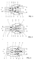
- Figs. 1, 2 and 3 show an end portion of a first duct 1, which forms part of a first length of duct with a first inner diameter d, and an initial portion of a second duct 2, which forms part of a second length of duct with a second inner diameter D, with D > d.
- the end portion of duct 1 and the initial portion of duct 2 are coupled by means of a coupling piece 3, which at one end has an inner diameter substantially equal to the outer diameter d + 2w of the duct 1, and at the other end has an inner diameter substantially equal to the outer diameter D + 2W of the duct 2, where w is the wall thickness of the duct 1 and W is the wall thickness of the duct 2.
- O-rings 4 and 5 are provided on the inside of the coupling piece 3.
- Reference numeral 6 denotes an end of a cable, in particular a telecommunication cable, and more particularly a telecommunication cable with optical glass fibers, to be installed in a ducting system of which ducts 1 and 2 form a part.
- the end 6 is connected to the body 8 of a pulling element 7 so as to be resistant to tensile strain.
- the body in a manner known per se, is provided with flexible members 9 in some form, which abut against the inner wall of the duct 1, in order that if a source of fluid under pressure, for instance a source of compressed air, is connected to the other end, not shown, of duct 1, the pulling element 7 is propelled through the duct as a result of the pressure of the fluid.
- Such a pulling element 7 is generally known from, for instance, EP-A-0,445,858 and can be completely closed in cross section but can also be provided with openings through which a part of the fluid can pass, as explained in the aforementioned European patent application.
- the pulling element 7 constitutes a first part of a pulling element consisting of two parts, and the forward end - viewed in the direction of insertion of the cable end 6 - of the body 8 of the pulling element part 7 is provided with a coupling member 10.
- the coupling member consists of a part of a magnetic coupling, and in the embodiment according to Figs. 2 and 3 it consists of a part of a mechanical coupling.
- a second pulling element part 11 is arranged, with a body 12 and flexible members 13, which abut against the inner wall of the duct 2 and fulfil the same function as the flexible members 9 of the pulling element part 7 in the duct 1.
- the body 12 is provided with coupling means 14 capable of cooperating with the coupling member 10 at the end of the pulling element part 7.
- the coupling member 10 is an element of ferromagnetic material or a magnetic element and the coupling means 14 consist of a magnetic element or a ferromagnetic material, at least one of the elements 10 and 14 being a magnetic element.
- the element 14 and the body 12 of the pulling element part 11 have a central opening.
- the element 14 can be provided with a recess 14', into which element 10 fits, and optionally with a rubber O-ring 15 to optimize the seal.
- the coupling member 10 consists of an extension 8' of the body 8, which fits within the coupling means 14, which consist of the central opening in the body 12 of the pulling element part 11.
- the end 8' is provided with a hook 10', of such length that the hook-shaped end 10'' of the hook 10' projects beyond the forward end of the opening in the body 12 of the pulling element part 11 when the body 8 of the pulling element part 7 rests against the proximal end of the body 12 of the pulling element part 11.
- this last can be provided with an O-ring 16.
- the coupling member 10 consists of an extension of the body 8 of the pulling element part 7, having at the end thereof a barb in the form of a flexible member 10', for instance a rubber disc, which closes off the central opening as it passes therethrough and, after passing therethrough, forms a stop at the forward end of the body 12, which stop seals the central opening 14 as soon as the compressed air pressure strikes the second pulling element part.
- a source of compressed air is connected to the end of the duct 1 that is not shown, so that the pulling element part 7, as a result of the compressed air pressure, is moved through the duct 1 and thus installs the cable end 6 and hence a cable in the duct.
- the air cushion that is built up in front of the pulling element part 7 can escape via the central opening in the body 12 of the pulling element part 11.
- the coupling member 10 engages the coupling means 14, whereby either a magnetic coupling or a mechanical coupling between the two pulling element parts is produced, and the central opening 19 in the body 12 is closed off, so that the pulling element part 11 can take over the function of the pulling element part 7 to guide the cable end 6 through the duct 2.
- the coupling should be completed before the pulling element part 7 leaves the duct 1 and the air pressure strikes the pulling element part 11.
- the pulling element part 11 can, for instance, be placed against a cam-shaped ridge 18 on the inside of the coupling piece.
- the body 12 of the second pulling element part can be provided with an air passage in such a manner that it is maintained also after the coupling with the first part, thereby to realize for the second portion of the length of duct a semi-open pulling element with the advantages described in EP-A-0,445,858.
- the pulling element according to the invention is particularly suitable for use in installing cables in ducting lines comprising ducts with more than one duct diameter, increasing in the installing direction.
- Such transitions from a first duct diameter to a second, greater duct diameter can, for instance, occur between two different sections of a telecommunications network, for instance because one section was laid at a later time than the other section.
- often smaller duct diameters are installed because:
- the pulling element can consist of more than two parts, each having a cross section adapted to a specific duct diameter, thereby enabling a cable to be installed by means of air pressure in a ducting line comprising ducts having more than two different, successively greater duct diameters.
Abstract
Description
- a need arises for a greater concentration of cores in the network to be installed;
- the cable diameters become smaller, for instance due to the transition from copper cable to glass fiber cable;
- improvements in the art enable an increasingly higher degree of miniaturization.
Claims (11)
- A pulling element (7, 11) with a body (8, 12) having an end which is connectable to a cable (6) to be installed in a duct and having another end, the body being provided round about with flexible members (9, 13) intended for sealing engagement with the inner wall of such a duct, characterized in that the body of the pulling element consists at least of a first part, which is provided with flexible members (9) suitable for engagement with the inner wall of a duct (1) with a first inner diameter (d), which first part is provided at the other end with a coupling member (10), and a second part, comprising a central longitudinal opening (19), flexible members (13) provided on the second part, which are suitable for engagement with the inner wall of a duct (2) with a second inner diameter (D), which is greater than the first inner diameter, and coupling means (14) capable of cooperating with the coupling member (10) of the first part so as to actively couple the two parts when the first part of the body (8) of the pulling element, during the installation of a cable (6), comes within the proximity of the second part of the body (12) of the pulling element.
- A pulling element according to claim 1, characterized in that the coupling member (10) and the coupling means (14) form a magnetic coupling.
- A pulling element according to claim 2, characterized in that the coupling member (10) consists of a ferromagnetic material or of magnetic material and that the coupling means (14) likewise consist of a ferromagnetic or of a magnetic material, at least one of the two consisting of a magnetic material.
- A pulling element according to claim 1, characterized in that the coupling member (10) and the coupling means (14) form a mechanical coupling.
- A pulling element according to claim 4, characterized in that the coupling member (10) consists of a hook-shaped extension (10") of the body (8) of the first part of the pulling element, which upon coupling engages via the opening (19) in the body (12) of the second part of the pulling element the forward end thereof.
- A pulling element according to claim 4, characterized in that the coupling member (10) consists of an extension of the body (8) of the first part of the pulling element, having at the end thereof a flexible disc-shaped member (10') which upon coupling engages via the opening (19) in the body (12) of the second part of the pulling element the forward end thereof.
- A pulling element according to any one of claims 1-6, characterized in that means (14', 16) are provided for airtightly sealing the coupling after it has been effected.
- A pulling element according to any one of claims 1-6, characterized in that the first part of the body of the pulling element is provided with a longitudinal opening.
- A pulling element according to any one of claims 1-6, characterized in that means are arranged for providing in the pulling element an air passage when the first part and the second part of the body are coupled.
- A ducting system for cables, in particular telecommunication cables, consisting of a first length of duct (1) with a first diameter (d) and a second length of duct (2) with a second, greater diameter (D), there being provided a coupling piece (3) for connecting the end of the first length of duct to the beginning of the second length of duct (2), characterized in that in the coupling piece (3) or in the initial portion of the second length of duct a pulling element (7, 11) is arranged, comprising a body (12) with a longitudinal opening (19), flexible members (13) attached to the body, which are in engagement with the portion of the inner wall of the coupling piece (3) that has substantially the same diameter as the second length of duct (2) or with the inner wall of the second length of duct (2) itself, and coupling means (14) arranged on the end of the body (12) proximal to the first length of duct (1).
- A coupling piece (3) for coupling a duct (1) with a first diameter (d) and a duct (2) with a second, greater diameter (D), there being provided in the portion of the coupling piece (3) intended for receiving the duct (2) with the second diameter a pulling element (7, 11) comprising a body (12) with a longitudinal opening (19), flexible members (13) attached to the body (12), which are in engagement with the portion of the inner wall of the coupling piece (3) that has substantially the same dimension as the inner diameter of the second duct (2), and coupling means (14) which are arranged on the end of the body proximal to the portion of the coupling piece (3) that is intended for receiving the first duct (1).
Applications Claiming Priority (2)
| Application Number | Priority Date | Filing Date | Title |
|---|---|---|---|
| NL1003130A NL1003130C2 (en) | 1996-05-15 | 1996-05-15 | Puller for installing a cable in a tube as well as a piping provided with such a puller. |
| NL1003130 | 1996-05-15 |
Publications (2)
| Publication Number | Publication Date |
|---|---|
| EP0808007A1 EP0808007A1 (en) | 1997-11-19 |
| EP0808007B1 true EP0808007B1 (en) | 2000-09-20 |
Family
ID=19762867
Family Applications (1)
| Application Number | Title | Priority Date | Filing Date |
|---|---|---|---|
| EP97201464A Expired - Lifetime EP0808007B1 (en) | 1996-05-15 | 1997-05-15 | Pulling element for installing a cable in a duct and ducting system comprising such pulling element |
Country Status (10)
| Country | Link |
|---|---|
| US (1) | US6047954A (en) |
| EP (1) | EP0808007B1 (en) |
| AT (1) | ATE196567T1 (en) |
| CZ (1) | CZ148597A3 (en) |
| DE (1) | DE69703137T2 (en) |
| DK (1) | DK0808007T3 (en) |
| ES (1) | ES2152622T3 (en) |
| GR (1) | GR3034999T3 (en) |
| NL (1) | NL1003130C2 (en) |
| PT (1) | PT808007E (en) |
Families Citing this family (9)
| Publication number | Priority date | Publication date | Assignee | Title |
|---|---|---|---|---|
| US6711328B2 (en) | 2001-07-12 | 2004-03-23 | Nkf Kabel B.V. | Installation bundle with spacer |
| DE60208490T2 (en) * | 2002-04-15 | 2006-07-27 | Koninklijke Kpn N.V. | Device and method for laying a duct body around a longitudinal element |
| US6811307B2 (en) | 2002-07-10 | 2004-11-02 | Kenneth J. Crowe | DTS measurement of HV cable temperature profile |
| US7992685B2 (en) * | 2002-07-11 | 2011-08-09 | Draka Comteq B.V. | Optical cable lubricator with reservoir |
| US6848541B2 (en) * | 2002-07-11 | 2005-02-01 | Nkf Kabel B.V. | Optical cable installation with cable lubricator |
| US8220121B2 (en) * | 2007-09-14 | 2012-07-17 | Cook Medical Technologies Llc | Device for loading a self-expandable prosthesis into a sheath |
| US20170085066A1 (en) * | 2015-09-22 | 2017-03-23 | Clayton Buck | System, Apparatus and Methods for a Fish Tape Guide |
| CN108799694B (en) * | 2018-07-26 | 2020-11-10 | 义乌市牛尔科技有限公司 | Soft robot for pipeline detection |
| RS65282B1 (en) | 2018-11-13 | 2024-03-29 | Plumettaz Holding S A | Installation of cables in an array of ducts |
Family Cites Families (12)
| Publication number | Priority date | Publication date | Assignee | Title |
|---|---|---|---|---|
| US920455A (en) * | 1906-12-14 | 1909-05-04 | Nat Water Main Cleaning Company | Device for passing cables through pipe-lines. |
| DE2604063A1 (en) * | 1976-02-03 | 1977-08-04 | Miguel Kling | SELF-PROPELLING AND SELF-LOCKING DEVICE FOR DRIVING ON CANALS AND FORMED BY LONG DISTANCES |
| GB2152621A (en) * | 1984-01-09 | 1985-08-07 | John Edmund Dawe | A method of threading an elongate flexible element through an elongate passage |
| JPH02146910A (en) * | 1988-11-24 | 1990-06-06 | Akiyuki Shima | Induction cap structure |
| JP2756168B2 (en) * | 1990-02-21 | 1998-05-25 | 古河電気工業株式会社 | How to draw a pipe into a pipeline |
| US5474277A (en) * | 1990-02-27 | 1995-12-12 | Koninklijke Ptt Nederland N.V. | Pulling plug aided by drag forces of a fluid medium for a portion of which the plug has a leaking aperture |
| US5197715A (en) * | 1990-02-27 | 1993-03-30 | Koninklijke Ptt Nederland N.V. | Method for pulling plug for installing a cable in a cable conduit |
| ATE89954T1 (en) * | 1990-02-27 | 1993-06-15 | Nederland Ptt | PROCEDURE AND PULL PLUG FOR INSTALLATION OF A CABLE INTO A MANIFOLD. |
| JP2802808B2 (en) * | 1990-03-27 | 1998-09-24 | 日本電信電話株式会社 | Optical fiber cable laying method |
| AU643554B2 (en) * | 1991-04-10 | 1993-11-18 | Kiyoshi Horii | Device for passing wire |
| FR2677501A1 (en) * | 1991-06-05 | 1992-12-11 | Pecot Alain | Pig (rabbit, go-devil) for pulling a cable through a conduit (pipe) especially of the telecommunications cable type |
| JPH05260622A (en) * | 1992-03-11 | 1993-10-08 | Mitsubishi Electric Corp | Wire stretching apparatus in conduit |
-
1996
- 1996-05-15 NL NL1003130A patent/NL1003130C2/en not_active IP Right Cessation
-
1997
- 1997-05-13 US US08/854,982 patent/US6047954A/en not_active Expired - Fee Related
- 1997-05-14 CZ CZ971485A patent/CZ148597A3/en unknown
- 1997-05-15 PT PT97201464T patent/PT808007E/en unknown
- 1997-05-15 EP EP97201464A patent/EP0808007B1/en not_active Expired - Lifetime
- 1997-05-15 ES ES97201464T patent/ES2152622T3/en not_active Expired - Lifetime
- 1997-05-15 AT AT97201464T patent/ATE196567T1/en not_active IP Right Cessation
- 1997-05-15 DE DE69703137T patent/DE69703137T2/en not_active Expired - Lifetime
- 1997-05-15 DK DK97201464T patent/DK0808007T3/en active
-
2000
- 2000-12-06 GR GR20000402689T patent/GR3034999T3/en not_active IP Right Cessation
Also Published As
| Publication number | Publication date |
|---|---|
| ATE196567T1 (en) | 2000-10-15 |
| DK0808007T3 (en) | 2000-12-11 |
| EP0808007A1 (en) | 1997-11-19 |
| DE69703137T2 (en) | 2001-05-17 |
| GR3034999T3 (en) | 2001-03-30 |
| US6047954A (en) | 2000-04-11 |
| ES2152622T3 (en) | 2001-02-01 |
| CZ148597A3 (en) | 1997-12-17 |
| PT808007E (en) | 2001-02-28 |
| DE69703137D1 (en) | 2000-10-26 |
| NL1003130C2 (en) | 1997-11-18 |
Similar Documents
| Publication | Publication Date | Title |
|---|---|---|
| EP0808007B1 (en) | Pulling element for installing a cable in a duct and ducting system comprising such pulling element | |
| US6619697B2 (en) | Y-branch splittable connector | |
| AU2007200520B2 (en) | Improvements in or relating to tube couplings for connecting a pair of conduits for carrying a cable | |
| EP2128675A1 (en) | Optical fiber cable with optical connector, method of passing the optical fiber cable, and pulling part and optical connector used for the method | |
| US6614962B1 (en) | Method and a device for installing optical fibres | |
| ES2181843T3 (en) | METHOD FOR INSTALLING A TUBE OR A BEAM OF PIPES IN AN EXISTING TUBULAR DUCT. | |
| US5197715A (en) | Method for pulling plug for installing a cable in a cable conduit | |
| WO1996010712B1 (en) | A universal pipe coupling with a u-shaped clip member | |
| EP1042696B1 (en) | Method of inserting a light transmitting member into a tube | |
| FI100493B (en) | Method and pull plug used to install the cable in the cable pipe | |
| EP1303895B1 (en) | Method for installing a duct in the ground and device for perfoming this method | |
| AU664376B2 (en) | Empty conduit with detachable cable assembly and method of making same | |
| US6109595A (en) | Apparatus and method for projecting lines | |
| JP3894868B2 (en) | Cable wiring jig | |
| EP1391973B1 (en) | Conduit glue bag, conduit glue strips and methods for installing cable in sewer pipe | |
| WO1997045668A1 (en) | Tube connector for connecting tubes intended for installing cables therein | |
| JP4117861B2 (en) | Insertion method | |
| JP2000134744A (en) | Removing method for cable laid in conduit | |
| CA1132697A (en) | Method and apparatus for enclosing a cable splice | |
| JPH0336909A (en) | Cable passing method and conduit communicating means | |
| JPS60116985A (en) | Method for passing wire through pipe | |
| JP2001327020A (en) | Cable-passing construction method | |
| JPH09140021A (en) | Connector and connecting method for communication line inserting tube |
Legal Events
| Date | Code | Title | Description |
|---|---|---|---|
| PUAI | Public reference made under article 153(3) epc to a published international application that has entered the european phase |
Free format text: ORIGINAL CODE: 0009012 |
|
| AK | Designated contracting states |
Kind code of ref document: A1 Designated state(s): AT BE CH DE DK ES FI FR GB GR IE IT LI LU NL PT SE |
|
| 17P | Request for examination filed |
Effective date: 19980505 |
|
| RAP3 | Party data changed (applicant data changed or rights of an application transferred) |
Owner name: KONINKLIJKE KPN N.V. |
|
| GRAG | Despatch of communication of intention to grant |
Free format text: ORIGINAL CODE: EPIDOS AGRA |
|
| 17Q | First examination report despatched |
Effective date: 19991008 |
|
| GRAG | Despatch of communication of intention to grant |
Free format text: ORIGINAL CODE: EPIDOS AGRA |
|
| GRAH | Despatch of communication of intention to grant a patent |
Free format text: ORIGINAL CODE: EPIDOS IGRA |
|
| GRAH | Despatch of communication of intention to grant a patent |
Free format text: ORIGINAL CODE: EPIDOS IGRA |
|
| GRAA | (expected) grant |
Free format text: ORIGINAL CODE: 0009210 |
|
| AK | Designated contracting states |
Kind code of ref document: B1 Designated state(s): AT BE CH DE DK ES FI FR GB GR IE IT LI LU NL PT SE |
|
| REF | Corresponds to: |
Ref document number: 196567 Country of ref document: AT Date of ref document: 20001015 Kind code of ref document: T |
|
| REG | Reference to a national code |
Ref country code: CH Ref legal event code: EP |
|
| REG | Reference to a national code |
Ref country code: CH Ref legal event code: NV Representative=s name: TROESCH SCHEIDEGGER WERNER AG |
|
| REF | Corresponds to: |
Ref document number: 69703137 Country of ref document: DE Date of ref document: 20001026 |
|
| REG | Reference to a national code |
Ref country code: IE Ref legal event code: FG4D |
|
| ET | Fr: translation filed | ||
| REG | Reference to a national code |
Ref country code: DK Ref legal event code: T3 |
|
| ITF | It: translation for a ep patent filed |
Owner name: BIANCHETTI - BRACCO - MINOJA S.R.L. |
|
| REG | Reference to a national code |
Ref country code: ES Ref legal event code: FG2A Ref document number: 2152622 Country of ref document: ES Kind code of ref document: T3 |
|
| REG | Reference to a national code |
Ref country code: PT Ref legal event code: SC4A Free format text: AVAILABILITY OF NATIONAL TRANSLATION Effective date: 20001129 |
|
| PLBE | No opposition filed within time limit |
Free format text: ORIGINAL CODE: 0009261 |
|
| STAA | Information on the status of an ep patent application or granted ep patent |
Free format text: STATUS: NO OPPOSITION FILED WITHIN TIME LIMIT |
|
| 26N | No opposition filed | ||
| REG | Reference to a national code |
Ref country code: GB Ref legal event code: IF02 |
|
| PGFP | Annual fee paid to national office [announced via postgrant information from national office to epo] |
Ref country code: LU Payment date: 20060517 Year of fee payment: 10 |
|
| PGFP | Annual fee paid to national office [announced via postgrant information from national office to epo] |
Ref country code: GR Payment date: 20060530 Year of fee payment: 10 |
|
| PGFP | Annual fee paid to national office [announced via postgrant information from national office to epo] |
Ref country code: PT Payment date: 20070426 Year of fee payment: 11 |
|
| PGFP | Annual fee paid to national office [announced via postgrant information from national office to epo] |
Ref country code: BE Payment date: 20070531 Year of fee payment: 11 |
|
| PGFP | Annual fee paid to national office [announced via postgrant information from national office to epo] |
Ref country code: DK Payment date: 20080509 Year of fee payment: 12 |
|
| PGFP | Annual fee paid to national office [announced via postgrant information from national office to epo] |
Ref country code: AT Payment date: 20080515 Year of fee payment: 12 |
|
| PGFP | Annual fee paid to national office [announced via postgrant information from national office to epo] |
Ref country code: FI Payment date: 20080514 Year of fee payment: 12 |
|
| PG25 | Lapsed in a contracting state [announced via postgrant information from national office to epo] |
Ref country code: GR Free format text: LAPSE BECAUSE OF NON-PAYMENT OF DUE FEES Effective date: 20071204 |
|
| PGFP | Annual fee paid to national office [announced via postgrant information from national office to epo] |
Ref country code: NL Payment date: 20080515 Year of fee payment: 12 |
|
| REG | Reference to a national code |
Ref country code: PT Ref legal event code: MM4A Free format text: LAPSE DUE TO NON-PAYMENT OF FEES Effective date: 20081117 |
|
| BERE | Be: lapsed |
Owner name: KONINKLIJKE *KPN N.V. Effective date: 20080531 |
|
| PG25 | Lapsed in a contracting state [announced via postgrant information from national office to epo] |
Ref country code: PT Free format text: LAPSE BECAUSE OF NON-PAYMENT OF DUE FEES Effective date: 20081117 |
|
| PG25 | Lapsed in a contracting state [announced via postgrant information from national office to epo] |
Ref country code: BE Free format text: LAPSE BECAUSE OF NON-PAYMENT OF DUE FEES Effective date: 20080531 |
|
| PG25 | Lapsed in a contracting state [announced via postgrant information from national office to epo] |
Ref country code: LU Free format text: LAPSE BECAUSE OF NON-PAYMENT OF DUE FEES Effective date: 20070515 |
|
| REG | Reference to a national code |
Ref country code: DK Ref legal event code: EBP |
|
| PG25 | Lapsed in a contracting state [announced via postgrant information from national office to epo] |
Ref country code: FI Free format text: LAPSE BECAUSE OF NON-PAYMENT OF DUE FEES Effective date: 20090515 Ref country code: AT Free format text: LAPSE BECAUSE OF NON-PAYMENT OF DUE FEES Effective date: 20090515 |
|
| NLV4 | Nl: lapsed or anulled due to non-payment of the annual fee |
Effective date: 20091201 |
|
| PG25 | Lapsed in a contracting state [announced via postgrant information from national office to epo] |
Ref country code: NL Free format text: LAPSE BECAUSE OF NON-PAYMENT OF DUE FEES Effective date: 20091201 |
|
| PG25 | Lapsed in a contracting state [announced via postgrant information from national office to epo] |
Ref country code: DK Free format text: LAPSE BECAUSE OF NON-PAYMENT OF DUE FEES Effective date: 20090531 |
|
| PGFP | Annual fee paid to national office [announced via postgrant information from national office to epo] |
Ref country code: IE Payment date: 20100527 Year of fee payment: 14 Ref country code: FR Payment date: 20100611 Year of fee payment: 14 Ref country code: ES Payment date: 20100525 Year of fee payment: 14 |
|
| PGFP | Annual fee paid to national office [announced via postgrant information from national office to epo] |
Ref country code: IT Payment date: 20100520 Year of fee payment: 14 Ref country code: DE Payment date: 20100521 Year of fee payment: 14 |
|
| PGFP | Annual fee paid to national office [announced via postgrant information from national office to epo] |
Ref country code: CH Payment date: 20100525 Year of fee payment: 14 |
|
| PGFP | Annual fee paid to national office [announced via postgrant information from national office to epo] |
Ref country code: SE Payment date: 20100517 Year of fee payment: 14 Ref country code: GB Payment date: 20100519 Year of fee payment: 14 |
|
| REG | Reference to a national code |
Ref country code: DE Ref legal event code: R119 Ref document number: 69703137 Country of ref document: DE |
|
| REG | Reference to a national code |
Ref country code: DE Ref legal event code: R119 Ref document number: 69703137 Country of ref document: DE |
|
| REG | Reference to a national code |
Ref country code: CH Ref legal event code: PL |
|
| REG | Reference to a national code |
Ref country code: SE Ref legal event code: EUG |
|
| GBPC | Gb: european patent ceased through non-payment of renewal fee |
Effective date: 20110515 |
|
| PG25 | Lapsed in a contracting state [announced via postgrant information from national office to epo] |
Ref country code: LI Free format text: LAPSE BECAUSE OF NON-PAYMENT OF DUE FEES Effective date: 20110531 Ref country code: CH Free format text: LAPSE BECAUSE OF NON-PAYMENT OF DUE FEES Effective date: 20110531 |
|
| REG | Reference to a national code |
Ref country code: FR Ref legal event code: ST Effective date: 20120131 |
|
| PG25 | Lapsed in a contracting state [announced via postgrant information from national office to epo] |
Ref country code: IT Free format text: LAPSE BECAUSE OF NON-PAYMENT OF DUE FEES Effective date: 20110515 |
|
| REG | Reference to a national code |
Ref country code: IE Ref legal event code: MM4A |
|
| PG25 | Lapsed in a contracting state [announced via postgrant information from national office to epo] |
Ref country code: IE Free format text: LAPSE BECAUSE OF NON-PAYMENT OF DUE FEES Effective date: 20110516 Ref country code: FR Free format text: LAPSE BECAUSE OF NON-PAYMENT OF DUE FEES Effective date: 20110531 |
|
| PG25 | Lapsed in a contracting state [announced via postgrant information from national office to epo] |
Ref country code: GB Free format text: LAPSE BECAUSE OF NON-PAYMENT OF DUE FEES Effective date: 20110515 |
|
| PG25 | Lapsed in a contracting state [announced via postgrant information from national office to epo] |
Ref country code: SE Free format text: LAPSE BECAUSE OF NON-PAYMENT OF DUE FEES Effective date: 20110516 |
|
| REG | Reference to a national code |
Ref country code: ES Ref legal event code: FD2A Effective date: 20130531 |
|
| PG25 | Lapsed in a contracting state [announced via postgrant information from national office to epo] |
Ref country code: DE Free format text: LAPSE BECAUSE OF NON-PAYMENT OF DUE FEES Effective date: 20111130 |
|
| PG25 | Lapsed in a contracting state [announced via postgrant information from national office to epo] |
Ref country code: ES Free format text: LAPSE BECAUSE OF NON-PAYMENT OF DUE FEES Effective date: 20110516 |