EP0807884B1 - Verfahren und Gerät zur Löschung von Objekten in einer Multifaden-Umgebung - Google Patents
Verfahren und Gerät zur Löschung von Objekten in einer Multifaden-Umgebung Download PDFInfo
- Publication number
- EP0807884B1 EP0807884B1 EP97303011A EP97303011A EP0807884B1 EP 0807884 B1 EP0807884 B1 EP 0807884B1 EP 97303011 A EP97303011 A EP 97303011A EP 97303011 A EP97303011 A EP 97303011A EP 0807884 B1 EP0807884 B1 EP 0807884B1
- Authority
- EP
- European Patent Office
- Prior art keywords
- state
- thread
- computer
- program code
- state value
- Prior art date
- Legal status (The legal status is an assumption and is not a legal conclusion. Google has not performed a legal analysis and makes no representation as to the accuracy of the status listed.)
- Expired - Lifetime
Links
Images


Classifications
-
- G—PHYSICS
- G06—COMPUTING OR CALCULATING; COUNTING
- G06F—ELECTRIC DIGITAL DATA PROCESSING
- G06F9/00—Arrangements for program control, e.g. control units
- G06F9/06—Arrangements for program control, e.g. control units using stored programs, i.e. using an internal store of processing equipment to receive or retain programs
- G06F9/46—Multiprogramming arrangements
- G06F9/52—Program synchronisation; Mutual exclusion, e.g. by means of semaphores
-
- Y—GENERAL TAGGING OF NEW TECHNOLOGICAL DEVELOPMENTS; GENERAL TAGGING OF CROSS-SECTIONAL TECHNOLOGIES SPANNING OVER SEVERAL SECTIONS OF THE IPC; TECHNICAL SUBJECTS COVERED BY FORMER USPC CROSS-REFERENCE ART COLLECTIONS [XRACs] AND DIGESTS
- Y10—TECHNICAL SUBJECTS COVERED BY FORMER USPC
- Y10S—TECHNICAL SUBJECTS COVERED BY FORMER USPC CROSS-REFERENCE ART COLLECTIONS [XRACs] AND DIGESTS
- Y10S707/00—Data processing: database and file management or data structures
- Y10S707/99941—Database schema or data structure
- Y10S707/99944—Object-oriented database structure
Definitions
- This invention relates to the field of object-oriented programming in a computer environment.
- Objects are self-contained, dearly defined, software modules that encapsulate procedures, such as business practices, and their data. Communicating with each other through carefully defined interfaces, objects allow complex solutions to be constructed similar to the manner in which computers are manufactured from standardized electronic components. Multiple levels of re-use and standardization are made possible, enabling engineers to produce modules, applications, and entire systems that are highly reusable and leveragable.
- Networked object technology allows applications access to objects and their shared services anywhere in the network, substantially independent of where the application or object resides.
- Networked objects also permit individual objects to be updated without the risk of disrupting the application or business process it models, facilitating the graceful, incremental evolution of complex systems. For example, if a new component fails, the component's predecessor can be re-instated quickly and transparently.
- An example of the networked object environment is the CORBA-compliant NEO product family from SunSoftTM, which provides for sharing of objects across networks and differing computing platforms.
- the OMG Common Object Request Broker Architecture (CORBA) is designed to allow different object systems from multiple vendors to interact with each other on a network.
- the CORBA specification comprises the following four components:
- the Network Object Request Broker is a CORBA-compliant network-based software system providing for the seamless location and execution of objects through a standard interface protocol, enabling objects and programs to transparently interact with each other across the network.
- the NEO ORB is implemented as one or more multi-threaded UNIX processes, providing scalable performance and availability as needed.
- the OMG has provided a portable source code reference implementation of the CORBA 2.0 Internet Inter-ORB Protocol to assist software vendors in testing and delivering OMG-compliant products.
- the Internet Inter-ORB Protocol (Internet IOP) provides a standardized way of connecting ORBs from different CORBA 2.0 compliant vendors, enabling them to communicate with each other.
- the current Internet IOP is based on TCP/IP protocols.
- the OMG CORBAservices definition describes the basic operations required for building distributed systems with objects, such as naming, events, properties, lifecycle and relationship services.
- the Interface Definition Language enables the separation of interface and implementation, allowing object implementation details to change without compromising the plug-and-play qualities of the object.
- the OMG IDL is a neutral interface definition of an object's operations, allowing the behavior of the object to be defined in IDL, but accommodating the automated transformation of the interface to the C, C++, Objective C, or Smalltalk languages.
- a multi-threaded environment such as that provided by UNIX, is typically used for supporting networked objects. Threads are subprocesses spawned off of larger processes for performing a certain function, e.g. performing a printing process, acting on a database object, etc. By supporting multiple threads, the system can serve many clients and processes simultaneously. This enables the sharing of objects and services on the network. Unfortunately, certain actions performed on an object become more complicated when the object is invoked by more than one thread.
- an Object Request Broker Daemon process receives object calls from the client processes registered to it.
- the ORB daemon locates the object on the network, and acts as the interface between the client process and the networked object.
- the ORB daemon may activate a NEO object server to act as a further interface for the object which may be a standard NEO object or, in some instances, a legacy process encapsulated in a NEO shell to perform as a NEO object.
- the NEO object server acts to instantiate the object as is necessary to respond to the calls forwarded by the ORB daemon.
- FIG. 3 is a block diagram of a CORBA-compliant networked object system. Multiple threads are represented by elements 300-303, where threads 300-301 are threads spawned from a first client process, Client Process 1, and threads 302-303 are threads spawned from a second client process, Client Process N. As indicated in Figure 3, a single client process can spawn any number of threads.
- Each of threads 300-303 is linked to Object Request Broker Daemon (ORBD) process 304.
- ORBD process 304 is in turn linked to a plurality of object servers represented by object server 305 and object server 307.
- a second ORBD process, ORBD process 310 is further linked to ORBD process 304. ORBD process 310 could also be coupled to further object servers and/or client processes (not shown).
- Object server 305 is linked to object 306.
- Object server 307 is linked to objects 308 and 309.
- ORBD process 304 receives object requests in the form of locate calls or requests from client process threads 300-303, and determines which object server is supporting the appropriate object. If the necessary server is not currently running, the server is activated and the object is instantiated. Information on the location of the object is returned in response to the locate call, and further requests between the thread and the object are directed by the location information.
- the same object can be similarly invoked by locate calls from other threads to establish interaction between the object and all applicable threads concurrently.
- ORB daemon 310 may provide a gateway for the networked object environment over a large network such as the Internet and/or it may provide cross-platform interaction by providing a platform dependent interface to clients and object servers in its own domain, while providing a standardized interface to ORBD 304.
- Object servers 305 and 307 provide access to objects or object libraries, such as shown by objects 306 and 308-309.
- Legacy objects that is those objects comprising stand-alone applications and other objects not originally designed for the networked object environment, are provided with an IDL shell that forms an interface through which the object server can access the functions of the legacy object.
- the objects and object servers may reside on the same computer as the client processes and the ORB daemon, or they may reside on separate computers within the network.
- the networked object environment is substantially independent of the base level implementation of the network.
- Figure 1 is a flow diagram illustrating the object invoking process.
- a thread obtains the address for an object from the ORB daemon, e.g., via a locate request.
- the thread invokes the object with a method invocation directed to the object's address.
- a branch occurs based on whether the object being invoked is already currently invoked by another thread. If the object is currently invoked, then, in step 104, the active invocation count is incremented by one. If the object is not currently invoked by another thread, then, in step 103, the active invocation count is initialized to reflect the invocation.
- Steps 103 and 104 lead into step 105.
- the object serves the thread in the requested manner.
- step 106 if the thread is done utilizing the method provided by the object, then the thread, or invocation, exits, and the number of active invocations is decremented by one in step 107. If the thread is not finished utilizing the object, then the process returns to step 105.
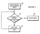
- FIG. 1 illustrates a process of the prior art for disposing of objects in the multi-threaded environment.
- a thread sends a call to delete the object.
- the number of active invocations for that object i.e., the current number of threads accessing the object
- the number of active invocations for that object is queried to determine if disposal can be performed without disrupting other processes. If the number of active invocations is zero, indicating that there are no other process threads accessing the object, then, in step 202, the object is deleted. However, if the current number of active invocations is not zero, then the object cannot be deleted yet.
- the disposing thread waits for active invocations to exit in step 203, and returns to step 201 to query the number of active invocations. Thus, the object is not deleted until the number of active invocations reaches zero.
- step 201 While the thread waits to delete the object, the number of active invocations is updated to reflect the completion of active threads and the arrival of new threads as illustrated in Figure 1.
- step 201 finally tests positive for zero active invocations, the object is deleted.
- the present invention provides a method and apparatus for providing thread-safe disposal of objects in a multi-threaded computer environment.
- a thread from a process sends a call to delete an object
- that thread typically waits for other threads interacting with that same object to clear.
- this waiting period it is common to have other threads invoking the same object, thus increasing rather than decreasing the number of active threads for that object.
- problems arise when more than one thread attempts to delete the object.
- the present invention associates a state machine with each object.
- the state machine is queried to detect the state.
- Invocations made on the object after the occurrence of a delete call interpret the object as having been deleted, and are not added to the active invocations for that object. Further, subsequent delete calls also interpret the object as having been deleted, and return a failure indication. The initial delete call returns success when the object is finally deleted. Thus, new invocations are precluded and multiple delete calls are handled appropriately.
- the state of an object is registered as "existing."
- the object enters a "to be deleted” state when a thread sends a call to delete the object.
- Subsequent invocation attempts by other threads interpret the state of the object as “deleted,” and thus are blocked from this instantiation of the object.
- the state of the object is changed to "deleted,” and the system disposes of the object.
- Figure 1 is a flow diagram of a prior art process for a thread invoking an object.
- Figure 2 is a flow diagram of a prior art process for a thread deleting an object.
- Figure 3 is a block diagram of a networked object environment, such as that defined under the OMG CORBA specification.
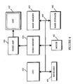
- FIG. 4 is a block diagram of a suitable hardware system for implementing the present invention.
- Figure 5 is a flow diagram of the process for a thread invoking an object according to one embodiment of the present invention.
- Figure 6 is a flow diagram of a process for a thread deleting an object according to one embodiment of the present invention.
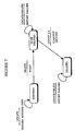
- Figure 7 is a diagram of an object state machine according to the method and apparatus of the present invention.
- the present invention can be implemented on a general purpose computer such as illustrated in Figure 4.
- a keyboard 410 and mouse 411 are coupled to a bi-directional system bus 418.
- the keyboard and mouse are for introducing user input to the computer system and communicating that user input to central processing unit (CPU) 413.
- CPU central processing unit
- the computer system of Figure 4 also includes a video memory 414, main memory 415 and mass storage 412, all coupled to bi-directional system bus 418 along with keyboard 410, mouse 411 and CPU 413.
- the mass storage 412 may include both fixed and removable media, such as magnetic, optical or magnetic optical storage systems or any other available mass storage technology.
- Bus 418 may contain, for example, thirty-two address lines for addressing video memory 414 or main memory 415.
- the system bus 418 also includes, for example, a 32-bit data bus for transferring data between and among the components, such as CPU 413, main memory 415, video memory 414 and mass storage 412.
- a 32-bit data bus for transferring data between and among the components, such as CPU 413, main memory 415, video memory 414 and mass storage 412.
- multiplex data/address lines may be used instead of separate data and address lines.
- the CPU 413 is a 32-bit microprocessor manufactured by Motorola, such as the 680X0 processor or a microprocessor manufactured by Intel, such as the 80X86, or Pentium processor. However, any other suitable microprocessor or microcomputer may be utilized.
- Main memory 415 is comprised of dynamic random access memory (DRAM).
- Video memory 414 is a dual-ported video random access memory. One port of the video memory 414 is coupled to video amplifier 416.
- the video amplifier 416 is used to drive the cathode ray tube (CRT) raster monitor 417.
- Video amplifier 416 is well known in the art and may be implemented by any suitable apparatus. This circuitry converts pixel data stored in video memory 414 to a raster signal suitable for use by monitor 417.
- Monitor 417 is a type of monitor suitable for displaying graphic images.
- Front ends systems for accessing the shared services of the network may comprise PC systems running WindowsTM, web browsers supporting the JavaTM application interface, workstations running SolarisTM, or other suitable systems, including combinations thereof.
- the computer systems described above are for purposes of example only.
- the present invention may be implemented in any type of computer system or programming or processing environment.
- the present invention provides a method and apparatus for ensuring that, upon the reception of an initial delete request, an object is ultimately deleted, and that the object is deleted in a timely fashion. Further, a process is provided for processing subsequent delete requests to prevent the addition of needlessly waiting threads to the server queue.
- the present invention utilizes a state machine to process invocations and delete requests.
- a state table is provided wherein the current state of an object is stored. The current number of active invocations may be stored there as well. Whenever a request is sent to the object, the state table is queried to determine the current state of the object. Depending on what the current state is and what type of request is being made, a suitable response to the request is determined.
- a framework for precluding certain types of requests during certain states is provided.
- the state table is implemented in a process as part of the object server.
- a three-state variable assigned to the object is sufficient to store the current state, though other methods for storing a state value may be used.
- a table of variables referenced by object, or a state table, wherein one variable is assigned to each object, may be implemented in an object server and queried by object as needed.
- a routine for providing a response to certain requests based on the contents of an object's state variable is provided in the object server.
- Figure 7 is a state diagram for one embodiment of a three-state state machine suitable for handling locate and delete calls for an object targeted in the call.
- the state of the object is designated as "existing.”
- Instantiation of the object may occur as part of the startup process of the associated object server, or instantiation may occur in response to the first locate request targeted at the object. In either case, the object is registered in the state table as "existing.”
- the state of the object is designated as "to be deleted.”
- the state of the object is designated as "deleted.”
- An active invocations value maintains a count,of the number of threads that are referencing an object.
- the object's active invocations value is changed to indicate the reference.
- the active invocations value is zero.
- This active invocations value may be stored in the state table as a second entry referenced by object, as a value stored separately on the object server, or as a value stored in the object itself. The state is advanced from "to be deleted” to "deleted" when the active invocations value reaches zero. Cleanup procedures for the object are initiated and the waiting thread returns and indicates successful deletion of the object.
- the delete request In the "deleted" state, if a request is received from a thread, the request is treated as if the target object is deleted, and no invocation takes place. If a delete request is received from a thread, the delete request returns indicating failure.
- One embodiment for a routine which implements the above state machine comprises software code which responds to requests by querying the state table to determine the target object's current state. Depending on the state and the request type, one portion of the software code returns a failure indication or a wait indication, or triggers the invocation on the object
- the state variable of the target object is updated upon the conditions specified with respect to Figure 7.
- FIG. 5 is a flow diagram of a process for a thread invoking an object according to one embodiment of the present invention.
- the process begins in step 500 when a thread obtains the object's address from the ORB daemon, e.g., via a locate request.
- the thread invokes the object with a method invocation directed to the object's address.
- the state machine checks the state variable assigned to the target object to determine the current state. If, in step 503, the object is not in the "existing" state, i.e., the object is either "to be deleted” or "deleted,” then, in step 504, the thread returns and reports failure. Thus, new invocations are precluded while the object is waiting to be deleted. If, however, in step 503, the state variable reflects that the target object is in the "existing" state, i.e., in standard operation, then the process progresses to step 505.
- step 505 a branch occurs based on whether the object being invoked is already currently invoked by another thread. If the object is currently invoked, then, in step 507, the active invocation count is incremented by one. If the object is not currently invoked by another thread, then, in step 506, the active invocation count is initialized to reflect the invocation.
- Steps 506 and 507 lead into step 508.
- the object serves the thread in the requested manner.
- step 509 if the thread is done utilizing the method provided by the object, then the thread, or invocation, exits, and the number of active invocations is decremented by one in step 510. If the thread is not finished utilizing the object, then the process returns to step 508.
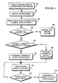
- FIG. 6 is a flow diagram of a process for a thread attempting to delete an object by sending a delete request according to one embodiment of the present invention.
- the process begins in step 600 when the thread sends the delete request to the target object.
- the state machine checks the state variable assigned to the target object to determine the current state. If, in step 602, the object is not in the "existing" state, i.e., the object is either "to be deleted” or "deleted,” then, in step 603, the thread returns and reports failure. Thus, new delete requests are handled appropriately when the object is already waiting to be deleted. If, however, in step 602, the state variable reflects that the target object is in the "existing" state, i.e., in standard operation, then the process progresses to step 604.
- step 604 the state variable for the target object is set to "to be deleted," and the requesting thread waits for the deletion process to complete.
- step 605 if the active invocations value is zero, indicating there are no active invocations, the process moves directly to step, 606. If, however, the active invocations value is greater than zero, indicating that active invocations remain for the target object, then, in step 609, the process waits for invocations to exit, then returns to step 605.
- Step 605 may test the number of active invocations at timed intervals, or it may test the number of active invocations after each increment or decrement operation. When step 605 tests positive for zero active invocations, the process progresses to step 606.
- step 606 When all of the active threads have cleared from the target object, in step 606, the state variable is set to "deleted.” Then, in step 607, the waiting thread responsible for the delete request returns with a success indicator. In the subsequent step, cleanup procedures are run to delete the object and reclaim the associated memory.
- the present invention ensures that the active invocations value will continue to decrease, further ensuring that the deletion operation occurs in a timely manner.
- the present invention prevents unnecessary threads from lingering and ensures the appropriate handling of multiple delete requests, i.e., the success of one delete request and the failure of all other delete requests.
Landscapes
- Engineering & Computer Science (AREA)
- Software Systems (AREA)
- Theoretical Computer Science (AREA)
- Physics & Mathematics (AREA)
- General Engineering & Computer Science (AREA)
- General Physics & Mathematics (AREA)
- Information Retrieval, Db Structures And Fs Structures Therefor (AREA)
- Multi Processors (AREA)
Claims (29)
- Verfahren zur Löschung von Objekten in einer Computerumgebung, umfassend folgende Schritte:(a) Verbinden eines Zustands mit einem Objekt in einer Computerumgebung;(b) Verändern des Zustands als Reaktion auf eine Objektlöschaufforderung von einem ersten Faden von einem ersten Zustandswert (602) zu einem Zwischenzustandswert (604); und(c) Verändern des Zustands vom Zwischenzustandswert zu einem dritten Zustandswert (606), wenn eine Anzahl von aktiven Aufrufen "Null" erreicht (605).
- Verfahren nach Anspruch 1, ferner umfassend folgende Schritte, wenn sich der Zustand zum dritten Zustandswert verändert:(a) Löschen des Objekts (608); und(b) Veranlassen des ersten Fadens, zurückzukehren (607).
- Verfahren nach Anspruch 1, ferner umfassend folgenden Schritt:Veranlassen eines zweiten Fadens, auf eine Objektlöschaufforderung vom zweiten Faden ein Versagen zu berichten (603), wenn der Zustand den Zwischenzustandswert umfaßt.
- Verfahren nach Anspruch 1, ferner umfassend folgenden Schritt:Ausschließen weiterer Aufrufe des Objekts, während der Zustand den Zwischenzustandswert umfaßt.
- Verfahren nach Anspruch 1, ferner umfassend folgende Schritte:(a) Aufrufen des Objekts als Reaktion auf eine Aufforderung vom ersten Faden (501); und(b) Festlegen des Zustands beim Aufruf durch den ersten Faden auf den ersten Zustandswert (506).
- Verfahren nach Anspruch 1, wobei der erste Zustandswert eine Angabe "vorhanden" umfaßt.
- Verfahren nach Anspruch 1, wobei der Zwischenzustandswert eine Angabe "zu löschen" umfaßt.
- Verfahren nach Anspruch 1, wobei der dritte Zustandswert eine Angabe "gelöscht" umfaßt.
- Verfahren nach Anspruch 1, wobei der Zustand in einer Tabelle bewahrt wird, auf die nach dem Objekt verwiesen wird.
- Computerprogrammcodeerzeugnis, umfassend ein computerverwendbares Medium, das in sich beinhaltend einen computerlesbaren Programmcode zur Löschung von Objekten in einer Multifaden-Umgebung aufweist, wobei das Computerprogrammerzeugnis umfaßt:(a) einen computerlesbaren Programmcode, der ausgerichtet ist, um einen Computer zu veranlassen, einen Zustand mit einem Objekt zu verbinden;(b) einen computerlesbaren Programmcode, der ausgerichtet ist, um einen Computer zu veranlassen, den Zustand als Reaktion auf eine Objektlöschaufforderung von einem ersten Faden von einem ersten Zustandswert (602) zu einem Zwischenzustandswert (604) zu verändern; und(c) einen computerlesbaren Programmcode, der ausgerichtet ist, um den Zustand vom Zwischenzustandswert zu einem dritten Zustandswert (606) zu verändern, wenn die Anzahl von aktiven Aufrufen "Null" erreicht (605).
- Computerprogrammcodeerzeugnis nach Anspruch 10, ferner umfassend:(a) einen computerlesbaren Programmcode, der ausgerichtet ist, um einen Computer zu veranlassen, das Objekt zu löschen (608), wenn sich der Zustand zum dritten Zustandswert verändert; und(b) einen computerlesbaren Programmcode, der ausgerichtet ist, um einen Computer zu veranlassen, den ersten Faden zu einer Rückkehr zu veranlassen, wenn sich der Zustand zum dritten Zustandswert verändert (607),
- Computerprogrammcodeerzeugnis nach Anspruch 10, ferner umfassend:einen computerlesbaren Programmcode, der ausgerichtet ist, einen Computer zu veranlassen, einen zweiten Faden zu veranlassen, auf eine Objektlöschaufforderung vom zweiten Faden ein Versagen zu berichten (603), wenn der Zustand den Zwischenzustandswert umfaßt.
- Computerprogrammcodeerzeugnis nach Anspruch 10, ferner umfassend:einen computerlesbaren Programmcode, der ausgerichtet ist, einen Computer zu veranlassen, weitere Aufrufe des Objekts auszuschließen, während der Zustand den Zwischenzustandswert umfaßt.
- Computerprogrammcodeerzeugnis nach Anspruch 10, ferner umfassend:(a) einen computerlesbaren Programmcode, der ausgerichtet ist, einen Computer zu veranlassen, das Objekt als Reaktion auf eine Aufforderung vom ersten Faden (501) aufzurufen; und(b) einen computerlesbaren Programmcode, der ausgerichtet ist, einen Computer zu veranlassen, den Zustand beim Aufruf durch den ersten Faden auf den ersten Zustandswert festzulegen (506).
- Computerprogrammcodeerzeugnis nach Anspruch 10, wobei der erste Zustandswert eine Angabe "vorhanden" umfaßt.
- Computerprogrammcodeerzeugnis nach Anspruch 10, wobei der Zwischenzustandswert eine Angabe "zu löschen" umfaßt.
- Computerprogrammcodeerzeugnis nach Anspruch 10, wobei der dritte Zustandswert eine Angabe "Löschung" umfaßt.
- Computerprogrammcodeerzeugnis nach Anspruch 10, wobei der Zustand und die Anzahl an aktiven Aufrufen in einer Tabelle bewahrt werden, auf die nach dem Objekt verwiesen wird.
- Gerät zur Löschung von Objekten in einer Multifaden-Umgebung, umfassend:(a) ein Objekt, das eine Anzahl an aktiven Aufrufen aufweist; und(b) eine Zustandsmaschine, die auf Aufrufe, die an das Objekt gerichtet sind, reagiert.
- Gerät nach Anspruch 19, wobei die Zustandsmaschine eine Zustandstabelle aufweist, die mit dem Objekt verbunden ist.
- Gerät nach Anspruch 20, wobei die Zustandstabelle einen ersten Zustand, einen zweiten Zustand, und einen dritten Zustand umfaßt.
- Gerät nach Anspruch 19, wobei die Zustandsmaschine im ersten Zustand auf eine Löschaufforderung durch eine Veränderung zu einem zweiten Zustand reagiert.
- Gerät nach Anspruch 22, wobei die Zustandsmaschine im ersten Zustand auf eine Aufrufaufforderung durch ein Weiterleiten der Aufrufaufforderung zum Objekt reagiert.
- Gerät nach Anspruch 22, wobei die Zustandsmaschine im zweiten Zustand Aufrufaufforderungen ausschließt, und die Zustandsmaschine auf die Löschaufforderungen durch eine Rückgabe einer Versagensanzeige reagiert (603).
- Gerät nach Anspruch 24, wobei die Zustandsmaschine das Objekt löscht (608), wenn sich die Zustandsmaschine im zweiten Zustand befindet und die Anzahl an aktiven Aufrufen "Null" erreicht (605).
- Gerät nach Anspruch 25, wobei die Zustandsmaschine, wenn das Objekt gelöscht ist, eine Erfolgsanzeige (607) an einen Faden zurückgibt, der für das Veranlassen der Zustandsmaschine, sich vom ersten Zustand zum zweiten Zustand zu verändern, verantwortlich ist.
- Gerät nach Anspruch 25, wobei sich die Zustandsmaschine zu einem dritten Zustand verändert (606), wenn das Objekt gelöscht ist.
- Gerät nach Anspruch 25, wobei die Zustandsmaschine im dritten Zustand Aufrufaufforderungen ausschließt, und die Zustandsmaschine auf die Löschaufforderungen durch eine Rückgabe einer Versagensanzeige reagiert (603)
- Gerät nach Anspruch 19, wobei die Zustandsmaschine als ein Vorgang in einem Objektserver ausgeführt ist (305, 307).
Applications Claiming Priority (2)
| Application Number | Priority Date | Filing Date | Title |
|---|---|---|---|
| US08/650,314 US6247039B1 (en) | 1996-05-17 | 1996-05-17 | Method and apparatus for disposing of objects in a multi-threaded environment |
| US650314 | 1996-05-17 |
Publications (2)
| Publication Number | Publication Date |
|---|---|
| EP0807884A1 EP0807884A1 (de) | 1997-11-19 |
| EP0807884B1 true EP0807884B1 (de) | 2003-03-26 |
Family
ID=24608375
Family Applications (1)
| Application Number | Title | Priority Date | Filing Date |
|---|---|---|---|
| EP97303011A Expired - Lifetime EP0807884B1 (de) | 1996-05-17 | 1997-05-01 | Verfahren und Gerät zur Löschung von Objekten in einer Multifaden-Umgebung |
Country Status (4)
| Country | Link |
|---|---|
| US (1) | US6247039B1 (de) |
| EP (1) | EP0807884B1 (de) |
| JP (1) | JPH1049384A (de) |
| DE (1) | DE69720100D1 (de) |
Families Citing this family (15)
| Publication number | Priority date | Publication date | Assignee | Title |
|---|---|---|---|---|
| US6842898B1 (en) * | 1999-06-10 | 2005-01-11 | International Business Machines Corporation | Method and apparatus for monitoring and handling events for a collection of related threads in a data processing system |
| US7478403B1 (en) | 2000-04-21 | 2009-01-13 | Sun Microsystems, Inc. | Secure access to managed network objects using a configurable platform-independent gateway providing individual object-level access control |
| US7783720B1 (en) | 2000-04-21 | 2010-08-24 | Oracle America, Inc. | CORBA metadata gateway to telecommunications management network |
| US7228346B1 (en) * | 2000-04-21 | 2007-06-05 | Sun Microsystems, Inc. | IDL event and request formatting for corba gateway |
| US6813770B1 (en) | 2000-04-21 | 2004-11-02 | Sun Microsystems, Inc. | Abstract syntax notation to interface definition language converter framework for network management |
| US6950935B1 (en) | 2000-04-21 | 2005-09-27 | Sun Microsystems, Inc. | Pluggable authentication modules for telecommunications management network |
| US7206843B1 (en) | 2000-04-21 | 2007-04-17 | Sun Microsystems, Inc. | Thread-safe portable management interface |
| US6839748B1 (en) | 2000-04-21 | 2005-01-04 | Sun Microsystems, Inc. | Synchronous task scheduler for corba gateway |
| US6915324B1 (en) | 2000-04-21 | 2005-07-05 | Sun Microsystems, Inc. | Generic and dynamic mapping of abstract syntax notation (ASN1) to and from interface definition language for network management |
| US7010586B1 (en) | 2000-04-21 | 2006-03-07 | Sun Microsystems, Inc. | System and method for event subscriptions for CORBA gateway |
| US7228175B2 (en) | 2002-05-15 | 2007-06-05 | Cardiac Pacemakers, Inc. | Cardiac rhythm management systems and methods using acoustic contractility indicator |
| US7500242B2 (en) | 2003-09-08 | 2009-03-03 | Intel Corporation | Low-contention lock |
| US20060015872A1 (en) * | 2004-07-13 | 2006-01-19 | Pohl William N | Process management |
| US9436503B2 (en) * | 2013-10-31 | 2016-09-06 | Emu Solutions, Inc. | Concurrency control mechanisms for highly multi-threaded systems |
| US11175802B2 (en) * | 2018-09-21 | 2021-11-16 | Sap Se | Configuration object deletion manager |
Family Cites Families (4)
| Publication number | Priority date | Publication date | Assignee | Title |
|---|---|---|---|---|
| US4809168A (en) | 1986-10-17 | 1989-02-28 | International Business Machines Corporation | Passive serialization in a multitasking environment |
| US5295262A (en) | 1991-05-16 | 1994-03-15 | International Business Machines Corporation | Read-only access without blocking via access vectors |
| US5329619A (en) * | 1992-10-30 | 1994-07-12 | Software Ag | Cooperative processing interface and communication broker for heterogeneous computing environments |
| US5692183A (en) * | 1995-03-31 | 1997-11-25 | Sun Microsystems, Inc. | Methods and apparatus for providing transparent persistence in a distributed object operating environment |
-
1996
- 1996-05-17 US US08/650,314 patent/US6247039B1/en not_active Expired - Lifetime
-
1997
- 1997-05-01 EP EP97303011A patent/EP0807884B1/de not_active Expired - Lifetime
- 1997-05-01 DE DE69720100T patent/DE69720100D1/de not_active Expired - Lifetime
- 1997-05-19 JP JP9128409A patent/JPH1049384A/ja active Pending
Also Published As
| Publication number | Publication date |
|---|---|
| JPH1049384A (ja) | 1998-02-20 |
| EP0807884A1 (de) | 1997-11-19 |
| US6247039B1 (en) | 2001-06-12 |
| DE69720100D1 (de) | 2003-04-30 |
Similar Documents
| Publication | Publication Date | Title |
|---|---|---|
| US6629153B1 (en) | Method and apparatus for providing peer ownership of shared objects | |
| US5884022A (en) | Method and apparatus for controlling server activation in a multi-threaded environment | |
| EP0956687B1 (de) | Webagent zur anforderung von mehreren prozessen | |
| US6009464A (en) | Method and apparatus for enabling application programs to communicate with network clients and servers | |
| US6260077B1 (en) | Method, apparatus and program product for interfacing a multi-threaded, client-based API to a single-threaded, server-based API | |
| AU746391B2 (en) | Method and system for facilitating distributed software development in a distribution unaware manner | |
| US6185609B1 (en) | Method, apparatus and program to provide client access to a management information service residing on a server in a computer network system | |
| EP0807884B1 (de) | Verfahren und Gerät zur Löschung von Objekten in einer Multifaden-Umgebung | |
| US6983285B2 (en) | Apparatus and method for dynamically verifying information in a distributed system | |
| US6157959A (en) | Method and apparatus for providing portable kernel-mode support for fast interprocess communication | |
| US6487607B1 (en) | Methods and apparatus for remote method invocation | |
| US6393497B1 (en) | Downloadable smart proxies for performing processing associated with a remote procedure call in a distributed system | |
| US6687831B1 (en) | Method and apparatus for multiple security service enablement in a data processing system | |
| US6418464B1 (en) | Method and apparatus for coordination of client/server processes | |
| US20020091874A1 (en) | Deferred reconstruction of objects and remote loading for event notification in a distributed system | |
| US7051341B2 (en) | Method, system, and program for implementing a remote method call | |
| JP2001522086A (ja) | 宣言型パラダイムをサポートするステートレスなウェブ環境におけるトランザクションを実行するための方法および装置 | |
| US6704764B1 (en) | Method and apparatus for a servlet server class | |
| US6625641B1 (en) | Method and apparatus for providing client support without installation of server software | |
| US6687730B2 (en) | Timeout object for object-oriented, real-time process control system and method of operation thereof | |
| US6957427B1 (en) | Remote object activation in a distributed system | |
| KR20010041227A (ko) | 분산 시스템에서 정보를 동적으로 증명하기 위한 장치 및 방법 | |
| KR20010040971A (ko) | 분산 시스템에서 오브젝트의 지연된 재구성 및 이벤트통지를 위한 원격 로딩 |
Legal Events
| Date | Code | Title | Description |
|---|---|---|---|
| PUAI | Public reference made under article 153(3) epc to a published international application that has entered the european phase |
Free format text: ORIGINAL CODE: 0009012 |
|
| AK | Designated contracting states |
Kind code of ref document: A1 Designated state(s): DE FR GB NL SE |
|
| 17P | Request for examination filed |
Effective date: 19980519 |
|
| 17Q | First examination report despatched |
Effective date: 20010903 |
|
| GRAG | Despatch of communication of intention to grant |
Free format text: ORIGINAL CODE: EPIDOS AGRA |
|
| GRAG | Despatch of communication of intention to grant |
Free format text: ORIGINAL CODE: EPIDOS AGRA |
|
| GRAH | Despatch of communication of intention to grant a patent |
Free format text: ORIGINAL CODE: EPIDOS IGRA |
|
| GRAH | Despatch of communication of intention to grant a patent |
Free format text: ORIGINAL CODE: EPIDOS IGRA |
|
| GRAA | (expected) grant |
Free format text: ORIGINAL CODE: 0009210 |
|
| AK | Designated contracting states |
Designated state(s): DE FR GB NL SE |
|
| PG25 | Lapsed in a contracting state [announced via postgrant information from national office to epo] |
Ref country code: NL Free format text: LAPSE BECAUSE OF FAILURE TO SUBMIT A TRANSLATION OF THE DESCRIPTION OR TO PAY THE FEE WITHIN THE PRESCRIBED TIME-LIMIT Effective date: 20030326 Ref country code: FR Free format text: LAPSE BECAUSE OF FAILURE TO SUBMIT A TRANSLATION OF THE DESCRIPTION OR TO PAY THE FEE WITHIN THE PRESCRIBED TIME-LIMIT Effective date: 20030326 |
|
| REG | Reference to a national code |
Ref country code: GB Ref legal event code: FG4D |
|
| REF | Corresponds to: |
Ref document number: 69720100 Country of ref document: DE Date of ref document: 20030430 Kind code of ref document: P |
|
| RAP2 | Party data changed (patent owner data changed or rights of a patent transferred) |
Owner name: SUN MICROSYSTEMS, INC. |
|
| PGFP | Annual fee paid to national office [announced via postgrant information from national office to epo] |
Ref country code: FR Payment date: 20030528 Year of fee payment: 7 |
|
| PGFP | Annual fee paid to national office [announced via postgrant information from national office to epo] |
Ref country code: NL Payment date: 20030530 Year of fee payment: 7 |
|
| PG25 | Lapsed in a contracting state [announced via postgrant information from national office to epo] |
Ref country code: SE Free format text: LAPSE BECAUSE OF FAILURE TO SUBMIT A TRANSLATION OF THE DESCRIPTION OR TO PAY THE FEE WITHIN THE PRESCRIBED TIME-LIMIT Effective date: 20030626 |
|
| PG25 | Lapsed in a contracting state [announced via postgrant information from national office to epo] |
Ref country code: DE Free format text: LAPSE BECAUSE OF FAILURE TO SUBMIT A TRANSLATION OF THE DESCRIPTION OR TO PAY THE FEE WITHIN THE PRESCRIBED TIME-LIMIT Effective date: 20030627 |
|
| PGFP | Annual fee paid to national office [announced via postgrant information from national office to epo] |
Ref country code: DE Payment date: 20030724 Year of fee payment: 7 |
|
| NLT2 | Nl: modifications (of names), taken from the european patent patent bulletin |
Owner name: SUN MICROSYSTEMS, INC. |
|
| NLV1 | Nl: lapsed or annulled due to failure to fulfill the requirements of art. 29p and 29m of the patents act | ||
| PLBE | No opposition filed within time limit |
Free format text: ORIGINAL CODE: 0009261 |
|
| STAA | Information on the status of an ep patent application or granted ep patent |
Free format text: STATUS: NO OPPOSITION FILED WITHIN TIME LIMIT |
|
| EN | Fr: translation not filed | ||
| 26N | No opposition filed |
Effective date: 20031230 |
|
| PGFP | Annual fee paid to national office [announced via postgrant information from national office to epo] |
Ref country code: GB Payment date: 20160427 Year of fee payment: 20 |
|
| REG | Reference to a national code |
Ref country code: GB Ref legal event code: PE20 Expiry date: 20170430 |
|
| PG25 | Lapsed in a contracting state [announced via postgrant information from national office to epo] |
Ref country code: GB Free format text: LAPSE BECAUSE OF EXPIRATION OF PROTECTION Effective date: 20170430 |