EP0807784A2 - Fluorescent lighting fixtures - Google Patents
Fluorescent lighting fixtures Download PDFInfo
- Publication number
- EP0807784A2 EP0807784A2 EP97303202A EP97303202A EP0807784A2 EP 0807784 A2 EP0807784 A2 EP 0807784A2 EP 97303202 A EP97303202 A EP 97303202A EP 97303202 A EP97303202 A EP 97303202A EP 0807784 A2 EP0807784 A2 EP 0807784A2
- Authority
- EP
- European Patent Office
- Prior art keywords
- protective tube
- wire
- lighting fixture
- fluorescent lighting
- roulette
- Prior art date
- Legal status (The legal status is an assumption and is not a legal conclusion. Google has not performed a legal analysis and makes no representation as to the accuracy of the status listed.)
- Withdrawn
Links
- 230000001681 protective effect Effects 0.000 claims abstract description 37
- 238000012216 screening Methods 0.000 abstract description 8
- 238000000034 method Methods 0.000 description 2
- 229920003002 synthetic resin Polymers 0.000 description 2
- 239000000057 synthetic resin Substances 0.000 description 2
- 238000010276 construction Methods 0.000 description 1
- 239000011810 insulating material Substances 0.000 description 1
- 239000012212 insulator Substances 0.000 description 1
- 238000012423 maintenance Methods 0.000 description 1
- 239000000463 material Substances 0.000 description 1
Images


Classifications
-
- F—MECHANICAL ENGINEERING; LIGHTING; HEATING; WEAPONS; BLASTING
- F21—LIGHTING
- F21L—LIGHTING DEVICES OR SYSTEMS THEREOF, BEING PORTABLE OR SPECIALLY ADAPTED FOR TRANSPORTATION
- F21L14/00—Electric lighting devices without a self-contained power source, e.g. for mains connection
- F21L14/02—Electric lighting devices without a self-contained power source, e.g. for mains connection capable of hand-held use, e.g. inspection lamps
- F21L14/026—Electric lighting devices without a self-contained power source, e.g. for mains connection capable of hand-held use, e.g. inspection lamps having a linear light source
Definitions
- the present invention relates to a fluorescent lighting fixture used in construction sites of buildings, engineering sites of tunnels or subways, factories of automobile maintenance and repair, and the like.
- a slender screening plate 11 is provided in a gap between the fluorescent lamp 1 and a protective tube 2 for the lamp 1 to hide the electric wires 6.
- the above known fluorescent lighting fixture requires the above mentioned screening plate 11 to be inserted in the gap between the fluorescent lamp 1 and the protective tube 2, which causes to increase the number of parts of the fixture. As a result, an extra cost for materials involves and is responsible for a higher production cost.
- the fluorescent lighting fixture of the present invention includes a roulette configuration 5, or a knurling, dented portions of which extend longitudinally on a protective tube 2 for a fluorescent lamp 1, and a rib 8 having a long hole 7 in which a wire 6 is inserted.
- the roulette configuration 5 is preferably formed on the inner face of the protective tube 2. It may be provided on its entire circumference.
- the rib 8 may have a longitudinal slit 7a which merges into the long hole 7.
- a wire 6 to be inserted into the hole 7 may be a naked electric wire.
- the wire 6 inserted in the long hole 7 becomes less noticeable.
- the fluorescent lamp 1 is set alight, light reflects and the protective tube 2 becomes luminous, which makes the wire 6 hard to be seen.
- the roulette configuration 5 being provided on the inner face of the protective tube 2, the outside of the tube 2 may be kept smooth. When the outside of tube 2 becomes dirty, it may be cleaned simply by wiping.
- the protecting tube 2 having a slit 7a which merges into the long hole 7 is easy to be taken out from a mold in synthetic resin forming process.
- the diameter of the hole 7 can be reduced, and the reduced diameter thereof allows the projecting part of the rib 8 from the protective tube 2 to be smaller.
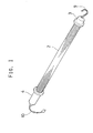
- FIG. 1 shows one example of the fluorescent lighting fixture of the present invention.
- a protective tube 2 houses a fluorescent lamp 1 and is provided with a closing member 3 at one open end and a gripping member 4 at the other open end.
- the protective tube 2 is made of translucent synthetic resin.
- Fig. 2 shows a protective tube 2 which is a cylindrical tube with a circle in section. But the shape of the tube 2 is not limited thereto, and it may be an ellipse, an oval, a polygon or the like in section.
- the protective tube 2, as shown in Fig. 2 has a roulette configuration 5 or a knurling on the entire inner circumference and dented portions of it extend longitudinally.
- a rib 8 which extends longitudinally and has a long hole 7 therein in which a wire 6 is to be inserted.
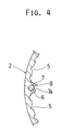
- a longitudinal slit 7a merging into the long hole 7 may be provided as occasional demands, as shown in Fig. 4.
- the roulette configuration 5 may be provided on the outer face of the protective tube 2 as shown in Fig. 5.
- the rib 8 is also provided on the outer face of the protective tube 2, but it may be separately provided on the inner face of the tube 2.
- the roulette configuration 5 may be provided only in the vicinity of the rib 8, instead of on the entire circumference.
- the closing member 3 is inserted into one end of the protective tube 2 to seal its open end. And a hanging member 9 may be projected on the closing member 3, so that the lighting fixture can be used in a suspended state.
- the gripping member 4 is inserted into the other end of the protective tube 2 to seal its open end.
- An electric cord 10 is brought into the inside of the gripping member 4.
- a ballast and the like In the space within the gripping member 4 is provided a ballast and the like.
- the roulette configuration 5 has a section of a series of semi-circular dents and the dented portions extends longitudinally to form a stripe pattern.
- the shape of the section is not limitative thereto, and it may be various shapes such as a series of triangular notches.
- the tube with a section of a series of semi-circular dents when the diameter of the semi-circle is set substantially equal to that of the long hole 7, the angles of reflection of light are unified and the protective tube 2 as a whole becomes luminous uniformly, and thereby the wire 6 becomes more effectively invisible.
- the wire 6 may be covered with insulating material such as rubber.
- the rib 8 serves as an insulator, so that a naked electric wire can be used.
- the diameter of the long hole 7 can be reduced and this allows the projecting part of the rib 8 from the protective tube 2 to be reduced.
- the long hole 7 of the rib 8 has the same diameter as that of the wire 6 and the wire 6 can be inserted straight.
- four ribs 8 are provided at equal intervals. Two wires 6 are selectively inserted in any two of four long holes 7 in the ribs 8.
- the fluorescent lighting fixture of the present invention has a roulette configuration 5 on the protective tube 2, dent portions of which extend longitudinally. Therefore a pattern of plural stripes appears on the protective tube 2, which makes the wire 6 inserted in the long hole 7 less noticeable.
- the fluorescent lamp 1 is lit, the reflection of light makes the entire protective tube 2 luminous, which causes the wire 6 hard to be seen.
- the slender screening plate 11 which is required in the gap between the fluorescent lamp 1 and the protective tube 2 for the foregoing known lighting fixture, becomes unnecessary. There is no need to increase the number of parts for the fixture in order to hide the wire and the production cost can be kept at the same, lower level.
- the fluorescent lighting fixture of the present invention has no slender screening plate 11 in the gap between the fluorescent lamp 1 and the protective tube 2, when the fluorescent lamp 1 is set alight, there is no shadow of the plate 11 and the entire light fixture becomes effectively luminous. As a result, sufficient luminous intensity can be secured.
Landscapes
- Engineering & Computer Science (AREA)
- General Engineering & Computer Science (AREA)
- Non-Portable Lighting Devices Or Systems Thereof (AREA)
- Arrangement Of Elements, Cooling, Sealing, Or The Like Of Lighting Devices (AREA)
- Common Detailed Techniques For Electron Tubes Or Discharge Tubes (AREA)
- Refuge Islands, Traffic Blockers, Or Guard Fence (AREA)
Abstract
Description
- The present invention relates to a fluorescent lighting fixture used in construction sites of buildings, engineering sites of tunnels or subways, factories of automobile maintenance and repair, and the like.
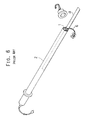
- In a known fluorescent lighting fixture of this type using a straight fluorescent lamp, terminals at both ends of the lamp must be connected with two electric wires. The wires extend parallel to the straight fluorescent lamp. In order not to show the wires, as shown in Figs. 6, 7, a
slender screening plate 11 is provided in a gap between thefluorescent lamp 1 and aprotective tube 2 for thelamp 1 to hide theelectric wires 6. - In the above known fluorescent lighting fixture, since the
slender screening plate 11 is inserted in the gap between thefluorescent lamp 1 and theprotective tube 2, when thelamp 1 is lit, thescreening plate 11 casts its shadow and the entire periphery of the fixture does not become luminous. Consequently, the sufficient luminous intensity (brightness) cannot be obtained. - The above known fluorescent lighting fixture requires the above mentioned
screening plate 11 to be inserted in the gap between thefluorescent lamp 1 and theprotective tube 2, which causes to increase the number of parts of the fixture. As a result, an extra cost for materials involves and is responsible for a higher production cost. - It would be desirable to be able to provide a fluorescent lighting fixture which solves the above problems, and makes the
wires 6 less noticeable without using theslender screening plate 11 in the gap between thefluorescent lamp 1 and theprotective tube 2. - The fluorescent lighting fixture of the present invention includes a
roulette configuration 5, or a knurling, dented portions of which extend longitudinally on aprotective tube 2 for afluorescent lamp 1, and arib 8 having along hole 7 in which awire 6 is inserted. - The
roulette configuration 5 is preferably formed on the inner face of theprotective tube 2. It may be provided on its entire circumference. - Furthermore, the
rib 8 may have a longitudinal slit 7a which merges into thelong hole 7. Awire 6 to be inserted into thehole 7 may be a naked electric wire. - Due to the
roulette configuration 5, or a knurled face, dented portions of which extend longitudinally on theprotective tube 2, a pattern with a number of stripes appears on the protectingtube 2. Therefore in the fluorescent lighting fixture of the present invention, thewire 6 inserted in thelong hole 7 becomes less noticeable. When thefluorescent lamp 1 is set alight, light reflects and theprotective tube 2 becomes luminous, which makes thewire 6 hard to be seen. - The
roulette configuration 5 being provided on the inner face of theprotective tube 2, the outside of thetube 2 may be kept smooth. When the outside oftube 2 becomes dirty, it may be cleaned simply by wiping. - Furthermore, the protecting
tube 2 having a slit 7a which merges into thelong hole 7 is easy to be taken out from a mold in synthetic resin forming process. - Additionally, with a naked electric wire as a
wire 6 to be inserted in thelong hole 7, the diameter of thehole 7 can be reduced, and the reduced diameter thereof allows the projecting part of therib 8 from theprotective tube 2 to be smaller. - Practical examples of the present invention will now be described with reference to the accompanying drawings, in which:
- Fig. 1 is a perspective view showing a fluorescent lighting fixture of the present invention;
- Fig. 2 is a sectional view of the protective tube of the fluorescent lighting fixture of the present invention;
- Fig. 3 is a partially enlarged sectional view of the protective tube of the fluorescent lighting fixture shown in Fig. 2;
- Fig. 4 is a partially enlarged sectional view of another protective tube of the fluorescent lighting fixture of the present invention;
- Fig. 5 is a sectional view of another protective tube of the fluorescent lighting fixture of the present invention;
- Fig. 6 is a perspective view of a known fluorescent lighting fixture;
- Fig. 7 is a sectional view of a protecting tube of a known fluorescent lighting fixture.
- Fig. 1 shows one example of the fluorescent lighting fixture of the present invention. A
protective tube 2 houses afluorescent lamp 1 and is provided with aclosing member 3 at one open end and a grippingmember 4 at the other open end. - The
protective tube 2 is made of translucent synthetic resin. Fig. 2 shows aprotective tube 2 which is a cylindrical tube with a circle in section. But the shape of thetube 2 is not limited thereto, and it may be an ellipse, an oval, a polygon or the like in section. Theprotective tube 2, as shown in Fig. 2, has aroulette configuration 5 or a knurling on the entire inner circumference and dented portions of it extend longitudinally. At a suitable circumferential point is provided arib 8 which extends longitudinally and has along hole 7 therein in which awire 6 is to be inserted. A longitudinal slit 7a merging into thelong hole 7 may be provided as occasional demands, as shown in Fig. 4. It allows an easy ripping from the mold in plastic forming process. Theroulette configuration 5 may be provided on the outer face of theprotective tube 2 as shown in Fig. 5. In this case, therib 8 is also provided on the outer face of theprotective tube 2, but it may be separately provided on the inner face of thetube 2. Theroulette configuration 5 may be provided only in the vicinity of therib 8, instead of on the entire circumference. - The
closing member 3 is inserted into one end of theprotective tube 2 to seal its open end. And a hangingmember 9 may be projected on theclosing member 3, so that the lighting fixture can be used in a suspended state. - The gripping
member 4 is inserted into the other end of theprotective tube 2 to seal its open end. Anelectric cord 10 is brought into the inside of the grippingmember 4. In the space within the grippingmember 4 is provided a ballast and the like. - The
roulette configuration 5 has a section of a series of semi-circular dents and the dented portions extends longitudinally to form a stripe pattern. The shape of the section is not limitative thereto, and it may be various shapes such as a series of triangular notches. In the tube with a section of a series of semi-circular dents, when the diameter of the semi-circle is set substantially equal to that of thelong hole 7, the angles of reflection of light are unified and theprotective tube 2 as a whole becomes luminous uniformly, and thereby thewire 6 becomes more effectively invisible. - The
wire 6 may be covered with insulating material such as rubber. When the wire is inserted in thehole 7 of therib 8, therib 8 serves as an insulator, so that a naked electric wire can be used. In use of a naked electric wire, the diameter of thelong hole 7 can be reduced and this allows the projecting part of therib 8 from theprotective tube 2 to be reduced. - It is advisable that the
long hole 7 of therib 8 has the same diameter as that of thewire 6 and thewire 6 can be inserted straight. In this example, fourribs 8 are provided at equal intervals. Twowires 6 are selectively inserted in any two of fourlong holes 7 in theribs 8. - The fluorescent lighting fixture of the present invention has a
roulette configuration 5 on theprotective tube 2, dent portions of which extend longitudinally. Therefore a pattern of plural stripes appears on theprotective tube 2, which makes thewire 6 inserted in thelong hole 7 less noticeable. When thefluorescent lamp 1 is lit, the reflection of light makes the entireprotective tube 2 luminous, which causes thewire 6 hard to be seen. Namely, theslender screening plate 11, which is required in the gap between thefluorescent lamp 1 and theprotective tube 2 for the foregoing known lighting fixture, becomes unnecessary. There is no need to increase the number of parts for the fixture in order to hide the wire and the production cost can be kept at the same, lower level. - Since the fluorescent lighting fixture of the present invention has no
slender screening plate 11 in the gap between thefluorescent lamp 1 and theprotective tube 2, when thefluorescent lamp 1 is set alight, there is no shadow of theplate 11 and the entire light fixture becomes effectively luminous. As a result, sufficient luminous intensity can be secured.
Claims (5)
- A fluorescent lighting fixture comprising a fluorescent lamp (1), a protective tube (2) for the lamp (1), and two electric wires (6), characterized in that the said protective tube (2) is provided with a roulette configuration (5) dented portions of which extend longitudinally on the said tube (2), and at least two longitudinal ribs (8) having a long hole (7) therein in which the said wires (6) are respectively inserted.
- A fluorescent lighting fixture according to Claim 1, wherein the said roulette configuration (5) is provided on an inner face of the said protective tube (2).
- A fluorescent lighting fixture according to Claim 1, wherein the said roulette configuration (5) is provided on an entire circumference on the said protective tube (2).
- A fluorescent lighting fixture according to Claim 1, further comprising a longitudinal slit (7a) which merges into the said long hole (7).
- A fluorescent lighting fixture according to Claim 1, wherein the said wires (6) are naked electric wires.
Applications Claiming Priority (2)
| Application Number | Priority Date | Filing Date | Title |
|---|---|---|---|
| JP123792/96 | 1996-05-17 | ||
| JP8123792A JPH09306216A (en) | 1996-05-17 | 1996-05-17 | Fluorescent lamp luminaire |
Publications (2)
| Publication Number | Publication Date |
|---|---|
| EP0807784A2 true EP0807784A2 (en) | 1997-11-19 |
| EP0807784A3 EP0807784A3 (en) | 1999-04-14 |
Family
ID=14869428
Family Applications (1)
| Application Number | Title | Priority Date | Filing Date |
|---|---|---|---|
| EP97303202A Withdrawn EP0807784A3 (en) | 1996-05-17 | 1997-05-12 | Fluorescent lighting fixtures |
Country Status (6)
| Country | Link |
|---|---|
| US (1) | US5909953A (en) |
| EP (1) | EP0807784A3 (en) |
| JP (1) | JPH09306216A (en) |
| KR (1) | KR970076971A (en) |
| CN (1) | CN1106525C (en) |
| TW (1) | TW337383U (en) |
Cited By (2)
| Publication number | Priority date | Publication date | Assignee | Title |
|---|---|---|---|---|
| WO2004113795A1 (en) * | 2003-06-26 | 2004-12-29 | Robert William Cairns | Microwave oven lamp and attachment |
| CN102098815A (en) * | 2009-12-09 | 2011-06-15 | 牛尾电机(苏州)有限公司 | Incandescent lamp |
Families Citing this family (7)
| Publication number | Priority date | Publication date | Assignee | Title |
|---|---|---|---|---|
| US7048410B2 (en) * | 2004-02-25 | 2006-05-23 | Murray Kutler | Support and enclosure structure for fluorescent light bulbs |
| USD553770S1 (en) * | 2006-04-21 | 2007-10-23 | Shen Jian Li | Work light |
| KR100745180B1 (en) * | 2007-04-19 | 2007-08-01 | (주)무림설계기술단 | Indoor lighting fixtures |
| JP5296391B2 (en) * | 2008-01-31 | 2013-09-25 | 京子 岡野 | Lighting device |
| USD612528S1 (en) * | 2008-05-08 | 2010-03-23 | Leddynamics, Inc. | Light tube assembly |
| US20110051445A1 (en) * | 2009-09-01 | 2011-03-03 | Keng-Chin Yeh | Vehicle Rear Lamp Assembly with CCFL |
| DE202011110657U1 (en) * | 2011-12-29 | 2015-08-03 | Werma Holding Gmbh + Co. Kg | Alarm lamp |
Family Cites Families (6)
| Publication number | Priority date | Publication date | Assignee | Title |
|---|---|---|---|---|
| US2874270A (en) * | 1959-02-17 | Portable work light | ||
| US2800965A (en) * | 1953-07-09 | 1957-07-30 | Benjamin Electric Mfg Co | Light-transmitting plastic sheet panels |
| US3136489A (en) * | 1962-01-24 | 1964-06-09 | Oharenko Vladimir | Safety work light |
| US3949216A (en) * | 1972-09-21 | 1976-04-06 | Howe Arnold P | Light dispersing structure for electric light fixture |
| US5173637A (en) * | 1990-07-19 | 1992-12-22 | Royal Lite Manufacturing And Supply Corp. | Fluorescent lamp with protective assembly |
| FR2668838B1 (en) * | 1990-11-07 | 1993-02-05 | Faure Pierre | DEVICE WITH TRANSPARENT ENCLOSURE PROVIDED WITH AN INVISIBLE INTERNAL AREA OUTSIDE THE ENCLOSURE. |
-
1996
- 1996-05-17 JP JP8123792A patent/JPH09306216A/en active Pending
-
1997
- 1997-05-05 TW TW086207188U patent/TW337383U/en unknown
- 1997-05-09 KR KR1019970017758A patent/KR970076971A/en not_active Withdrawn
- 1997-05-12 EP EP97303202A patent/EP0807784A3/en not_active Withdrawn
- 1997-05-15 US US08/857,106 patent/US5909953A/en not_active Expired - Fee Related
- 1997-05-16 CN CN97111043A patent/CN1106525C/en not_active Expired - Fee Related
Cited By (2)
| Publication number | Priority date | Publication date | Assignee | Title |
|---|---|---|---|---|
| WO2004113795A1 (en) * | 2003-06-26 | 2004-12-29 | Robert William Cairns | Microwave oven lamp and attachment |
| CN102098815A (en) * | 2009-12-09 | 2011-06-15 | 牛尾电机(苏州)有限公司 | Incandescent lamp |
Also Published As
| Publication number | Publication date |
|---|---|
| EP0807784A3 (en) | 1999-04-14 |
| CN1175082A (en) | 1998-03-04 |
| US5909953A (en) | 1999-06-08 |
| KR970076971A (en) | 1997-12-12 |
| JPH09306216A (en) | 1997-11-28 |
| TW337383U (en) | 1998-07-21 |
| CN1106525C (en) | 2003-04-23 |
Similar Documents
| Publication | Publication Date | Title |
|---|---|---|
| US4858088A (en) | Elongated lighting device | |
| US5909953A (en) | Fluorescent lighting fixture | |
| US6190021B1 (en) | Double-wing type lamp holder | |
| DE59908285D1 (en) | Lighting system with a high pressure discharge lamp | |
| US6971768B1 (en) | Decorative lighting system | |
| US5669707A (en) | Christmas lamp socket | |
| US5829863A (en) | Fiber optic X-mas tree | |
| US6634765B2 (en) | Light strip bendable to form various pattern | |
| BR9508988A (en) | Incandescent halogen lamp with bulb-free socket | |
| US4802072A (en) | Direction fixture for decorative lamp series | |
| US4122511A (en) | Lamp-shade for tubular lamps | |
| US4053761A (en) | Decorative item | |
| US2434951A (en) | Lighting equipment | |
| BR9805911A (en) | Process for the manufacture of an incandescent electric lamp | |
| US20030235049A1 (en) | Decoration bulb assembly | |
| US4156270A (en) | Outdoor lighting fixture | |
| EP0802367A3 (en) | Reflector lamp | |
| FR2770026B3 (en) | FLUORESCENT TUBE WITH UNIFORM LIGHTING | |
| US4127892A (en) | Lighted element for decoration | |
| US3435203A (en) | Color filter for light bulbs | |
| DE69618376D1 (en) | Double filament for incandescent lamp | |
| HK1008262A (en) | Fluorescent ligthing fixtures | |
| JP5296391B2 (en) | Lighting device | |
| US5886458A (en) | Lamp bulb with two filaments for Christmas tree light | |
| US3904865A (en) | Threaded bulb cover device |
Legal Events
| Date | Code | Title | Description |
|---|---|---|---|
| PUAI | Public reference made under article 153(3) epc to a published international application that has entered the european phase |
Free format text: ORIGINAL CODE: 0009012 |
|
| AK | Designated contracting states |
Kind code of ref document: A2 Designated state(s): DE FR GB IT |
|
| PUAL | Search report despatched |
Free format text: ORIGINAL CODE: 0009013 |
|
| AK | Designated contracting states |
Kind code of ref document: A3 Designated state(s): DE FR GB IT |
|
| 17P | Request for examination filed |
Effective date: 19990924 |
|
| 17Q | First examination report despatched |
Effective date: 20010608 |
|
| STAA | Information on the status of an ep patent application or granted ep patent |
Free format text: STATUS: THE APPLICATION IS DEEMED TO BE WITHDRAWN |
|
| 18D | Application deemed to be withdrawn |
Effective date: 20011019 |