EP0807780A1 - Vorrichtung zum dichten Verbinden von zwei glatten Rohren - Google Patents
Vorrichtung zum dichten Verbinden von zwei glatten Rohren Download PDFInfo
- Publication number
- EP0807780A1 EP0807780A1 EP97401049A EP97401049A EP0807780A1 EP 0807780 A1 EP0807780 A1 EP 0807780A1 EP 97401049 A EP97401049 A EP 97401049A EP 97401049 A EP97401049 A EP 97401049A EP 0807780 A1 EP0807780 A1 EP 0807780A1
- Authority
- EP
- European Patent Office
- Prior art keywords
- ring
- tubes
- sleeve
- strip
- perforations
- Prior art date
- Legal status (The legal status is an assumption and is not a legal conclusion. Google has not performed a legal analysis and makes no representation as to the accuracy of the status listed.)
- Granted
Links
- 230000008878 coupling Effects 0.000 claims abstract description 12
- 238000010168 coupling process Methods 0.000 claims abstract description 12
- 238000005859 coupling reaction Methods 0.000 claims abstract description 12
- 238000007789 sealing Methods 0.000 claims description 21
- 239000007787 solid Substances 0.000 claims description 5
- 230000000694 effects Effects 0.000 claims description 4
- 230000007423 decrease Effects 0.000 description 4
- 239000011521 glass Substances 0.000 description 2
- 238000004519 manufacturing process Methods 0.000 description 2
- 230000001627 detrimental effect Effects 0.000 description 1
- 238000000926 separation method Methods 0.000 description 1
Images

Classifications
-
- F—MECHANICAL ENGINEERING; LIGHTING; HEATING; WEAPONS; BLASTING
- F16—ENGINEERING ELEMENTS AND UNITS; GENERAL MEASURES FOR PRODUCING AND MAINTAINING EFFECTIVE FUNCTIONING OF MACHINES OR INSTALLATIONS; THERMAL INSULATION IN GENERAL
- F16L—PIPES; JOINTS OR FITTINGS FOR PIPES; SUPPORTS FOR PIPES, CABLES OR PROTECTIVE TUBING; MEANS FOR THERMAL INSULATION IN GENERAL
- F16L21/00—Joints with sleeve or socket
- F16L21/002—Sleeves or nipples for pipes of the same diameter; Reduction pieces
- F16L21/005—Sleeves or nipples for pipes of the same diameter; Reduction pieces made of elastic material, e.g. partly or completely surrounded by clamping devices
Definitions
- the present invention relates to a device for the sealed coupling of two smooth tubes arranged end to end, having substantially the same diameter.
- a device of this type which comprises a sleeve capable of being disposed around the opposite ends of the two tubes.
- This sleeve has two free ends provided with assembly lips which delimit between them an axial slot, the assembly lips being able to cooperate with means for tightening the sleeve capable of bringing said lips closer to one another.
- This device further comprises a sealing ring capable of being placed in the sleeve to surround the opposite ends of the two tubes.
- This ring is constituted by a flat strip which is wound on itself and has two free edges, located opposite one another and capable of coming into contact with each other when, the ring being located in the sleeve, the latter is tightened around the opposite ends of the tubes.
- Devices of this type are used, for example, for the end-to-end connection of two exhaust tubes.
- the sealing requirements of the fitting are increasing. We naturally tend to think that the more we tighten the sleeve on the tubes, the more the sealing is improved.
- the problem is that, when the sleeve is tightened, the diameter of the sealing ring is reduced, which brings these two free edges closer to one another. It is therefore necessary that the junction between the two free edges is as tight as possible and that the fact of tightening the sleeve more from the moment when the two free edges are in contact does not cause overlapping detrimental to the seal.
- French Patent 2,662,486 proposes a first solution to this problem by making the free edges of the ring bevel, so that these can be applied one against the other and offset transversely relative to one another. to when the diameter of the ring decreases.
- This solution is generally satisfactory, but it does not make it possible to completely control the support of the two free edges one against the other nor to ensure the setting of the ring inside the sleeve.
- the object of the present invention is to further improve the coupling device and to remedy the aforementioned drawbacks.
- the free edges of the sealing ring extend transversely to the longitudinal direction of the strip constituting this ring and that the ring comprises, at least in a region called "deformable region", located at in the vicinity of one of the free edges of the ring and extending over substantially the entire width of the strip which constitutes this ring, means for causing a deformation consisting in a reduction, in said deformable region, of the length of the band which constitutes the ring, when the free edges of the latter are pressed against one another under the effect of the tightening of the sleeve on the ends of the tubes.
- the free transverse edges of the sealing ring are automatically applied one against the other when the sleeve is tightened.
- the length of the band which constitutes the ring can decrease in the deformable region, so that the diameter of this ring can decrease without overlapping its free edges.
- the deformable region extending over substantially the entire width of the strip the latter can be adapted to slight differences in diameter of the two tubes to be connected, since the length of the strip may be greater in part of the deformable region than in another.
- the device comprises means for trapping the leaks liable to occur in the coupling zone of the ends of the tubes between at least a portion of the deformable region of the ring and one of the two elements constituted by the periphery internal of the sleeve and by the external peripheries of the tubes.
- the means for causing deformation in the deformable region may include a series of perforations or, alternatively, a series of thinned portions.
- the sealing ring advantageously has a sealing ring which projects towards the inside of this ring and is able to cooperate with the external peripheries of the tubes.
- this rod is formed by a fold of the edge of the ring inwards.
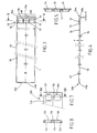
- the device comprises a sleeve 10, two free ends which extend substantially axially, are provided with assembly lips 12a and 12b. These lips delimit between them an axial slot 14 which, as shown in FIG. 1, tends to close when the sleeve is tightened.
- the lips 12a and 12b in fact cooperate with means for tightening the sleeve which bring them closer to one another.
- these tightening means comprise a bolt comprising a screw 16, the rod of which passes through two orifices 13a and 13b respectively formed in the lips 12a and 12b, and a nut 18 screwed onto this rod.
- the device which is used to connect two tubes having substantially the same diameter, can be placed around the opposite ends of these two tubes, ends shown in dashed lines broken in FIG. 2 and respectively designated by the references 20 and 22.
- the device further comprises a sealing ring 24 disposed in the sleeve 10 to surround the opposite ends of the two tubes 20 and 22.
- This ring is visible in FIG. 1.
- the ring 24 is constituted by a flat strip 26 , shown in Figures 3 to 5, which is rolled up on itself.
- the two longitudinal ends of the strip 26, 26a and 26b constitute two free edges which, when this strip is wound on itself to form the ring 24, are located opposite one another and are able to come in contact with each other when, the ring being disposed inside the sleeve, the latter is tightened around the ends of the tubes.
- the free edges 26a and 26b of the ring extend transversely to the longitudinal direction D of the strip 26.
- the ring has a region 28 called "deformable region". It can be seen that this region extends transversely over substantially the entire width l of the strip 26. In the longitudinal direction of the strip, the region 28 extends over a relatively small portion of the length L of the strip, by example between 3 and 10% and advantageously between 4 and 6% of the length L.
- the deformable region 28 equips only the free edge 26a, which constitutes an advantageous arrangement.
- a deformable region could be provided in the vicinity of each of the two free edges 26a and 26b.
- the ring includes means for causing a deformation consisting in a reduction, in this region, of the length of the strip 26, when the free edges 26a and 26b are urged to bear against one another under the effect of the tightening of the sleeve 10 on the ends of the tubes 20 and 22.
- the deformable region extends over practically the entire width l of the strip, the deformation may not be uniform over this entire width l .
- the ring 24 located inside the sleeve 10 surrounds the ends of the two tubes, the latter each extend substantially over one of the two halves m1 and m2 of the width of the strip which constitutes the ring.
- the decrease in length in the deformable region 28 may be greater in one of the two halves m1 and m2 than in the other. Due to the capacity of region 28 to deform not uniformly over the entire width l , the seal is therefore preserved even if the diameters of the two tubes are slightly different.
- the sealing ring obviously aims to create a closed space in the connection area of the tubes, between the external peripheries of the tubes and the internal periphery of the sealing ring.
- leaks may still occur in the connection area of the tubes, at the deformable region of the ring.
- the latter comprises means for trapping such leaks between at least part of the deformable region of the ring and one of the two elements constituted by the internal periphery of the sleeve 10 and through the external peripheries of the tubes 20 and 22. It will be seen below that these means may include folds suitably arranged in the deformable region.
- the means for causing the deformation of the strip in the deformable region 28 comprise a series of perforations which extend over substantially the entire width l of the strip 26.
- this series comprises three perforations 30, 32 and 34 aligned in the transverse direction of the strip.
- the central perforation 32 is separated from the other two by two solid preserved areas 36 and 38.
- the series of perforations may include more perforations or, on the contrary, include only one or two. If several perforations are present, it is preferable that the separation zones between two adjacent perforations, such as zones 36 and 38, are sufficiently small or sufficiently thin to be able to easily deform during tightening.
- the perforations can, as in the example shown, be quadrangular, but they can also have any satisfactory shape, for example a circular shape.
- one of the perforations in the series is located in the coupling zone of the ends of the tubes.
- this is the case with the central perforation 32 since the coupling zone of the ends of the tubes is located substantially in the median transverse plane P (plane of symmetry) of the ring.
- the raised edge 33 can be produced in the same operation as the perforation 32. When the ring is located inside the sleeve and when the latter is tightened on the tubes, the raised edge 33 can cooperate with the internal periphery 11 of the muff.
- the edge 33 is relatively flexible due to the weakness of its thickness e (for example from 5 to 30% of the thickness of the strip 26). When, the sleeve being tightened around the tube, the ring is itself tightened in this sleeve, the edge 33 is therefore able to come into tight contact with the internal periphery 11 of the sleeve.
- the other perforations, 30 and 34 can also be provided with borders similar to border 33.
- the ring 24 is disposed in the sleeve, so that the perforations of the series of perforations are located facing a solid part of the sleeve 10, that is to say that they are offset angularly with respect to the axial slot 14.
- the device advantageously includes means for defining the position of the ring in the sleeve so that the free edges 26a and 26b of this ring are angularly offset from the axial slot 14, as best seen on the magnifying glass of FIG. 1.
- the perforations being in the deformable region, therefore close to one of the free edges, this precaution makes it possible to ensure that the perforations are angularly offset relative to slot 14.
- Such positioning means are visible in Figures 4 and 6. They include for example a stamped 40 made in the ring and projecting radially outwardly from the latter.
- the periphery of the sleeve 10 comprises, for its part, a recess or a perforation 42, in which the stamp 40 is housed.
- the recess or the perforation 42 is formed in a flap 44 which extends along the periphery of the nozzle 10 and which was preserved during the production by folding of the assembly lips 12a and 12a and of the cutting of one of the openings 13a and 13b of the latter.
- FIGS. 7 and 8 a second scenario, illustrated by FIGS. 7 and 8 and in which such deformability is not required, can also be chosen.
- the strip 126 the end of which is shown in FIG. 7, has a deformable region 128 which comprises a series of perforations comprising two perforations 130 and 132, which are separated by a solid part 136.
- this second case is that where the series of perforations comprises at least two perforations separated by a solid part which is likely to be in the coupling zone of the ends of the tubes when the ring is placed inside the sleeve, itself arranged around the tubes. In this case, it is under zone 136 that leaks are likely to occur.
- the means for allowing the deformation of the strip in the deformable region may comprise a series of at least one thinned portion, that is to say a portion whose thickness, measured transversely to the plane of the strip is less than the thickness of this strip.
- the thinned portion has a thickness of between 10% and 40% of the thickness of the strip.
- these rods 48a and 48b come into tight contact.
- These rods are advantageously constituted by folds of the two free axial ends of the strip. These folds are preferably oblique, that is to say they are oriented relative to the plane of the strip so as to go, each, away from the longitudinal end of the strip in which they are formed. . This ensures that they bear directly against each other during contact with the free edges of the ring.
- the latter are less rigid than most of the ring.
- their thickness e ' is less than the thickness E of the strip and advantageously between 20 and 60% of this thickness.
- this ring has sealing rings 50, 150, disposed on each axial end of the ring, that is to say on each of the longitudinal edges of the strip which constitutes this ring and projecting towards the inside of the ring so as to cooperate with the external peripheries of the tubes.
- these sealing rods 50 or 150 are formed by folds of the edge of the ring, on the longitudinal edges of the strip which constitutes it, extending towards the inside of the Ring.
- the thickness of the folds 50 and 150 is advantageously much less than that of the ring.
- the set of folds 50 (or 150), 48a and 48b therefore forms a continuous fold which extends over the entire periphery of the band which constitutes the ring.
- the ring 26 To axially wedge the ring 26 inside the sleeve 10, the latter has, on its internal periphery, a hollow area forming a housing for the ring. This recessed area is produced by a substantially annular stamp 60, radially projecting outward from the sleeve.
- stampings 70 directed towards the inside of the ring, are used for wedging the ends 20 and 22 of the tubes, one with respect to the other.
Landscapes
- Engineering & Computer Science (AREA)
- General Engineering & Computer Science (AREA)
- Mechanical Engineering (AREA)
- Joints With Sleeves (AREA)
- Gasket Seals (AREA)
Applications Claiming Priority (2)
| Application Number | Priority Date | Filing Date | Title |
|---|---|---|---|
| FR9605905 | 1996-05-13 | ||
| FR9605905A FR2748542B1 (fr) | 1996-05-13 | 1996-05-13 | Dispositif pour l'accouplement etanche de deux tubes lisses |
Publications (2)
| Publication Number | Publication Date |
|---|---|
| EP0807780A1 true EP0807780A1 (de) | 1997-11-19 |
| EP0807780B1 EP0807780B1 (de) | 2002-03-20 |
Family
ID=9492061
Family Applications (1)
| Application Number | Title | Priority Date | Filing Date |
|---|---|---|---|
| EP19970401049 Expired - Lifetime EP0807780B1 (de) | 1996-05-13 | 1997-05-12 | Vorrichtung zum dichten Verbinden von zwei glatten Rohren |
Country Status (4)
| Country | Link |
|---|---|
| EP (1) | EP0807780B1 (de) |
| DE (1) | DE69711116T2 (de) |
| ES (1) | ES2173403T3 (de) |
| FR (1) | FR2748542B1 (de) |
Families Citing this family (2)
| Publication number | Priority date | Publication date | Assignee | Title |
|---|---|---|---|---|
| FR2794517B1 (fr) | 1999-06-02 | 2001-08-24 | Caillau Ets | Dispositif pour le raccordement etanche de deux tubes lisses |
| DE20210323U1 (de) | 2002-07-04 | 2002-09-26 | HJS Fahrzeugtechnik GmbH & Co., 58706 Menden | Rohrverbinder |
Citations (4)
| Publication number | Priority date | Publication date | Assignee | Title |
|---|---|---|---|---|
| US2227551A (en) * | 1939-06-07 | 1941-01-07 | Jolly L Morris | Pipe coupling and pipe clamp |
| FR2139899A1 (de) * | 1971-05-28 | 1973-01-12 | Mueller Co | |
| DE9207960U1 (de) * | 1992-06-13 | 1992-09-10 | KOMTEC GmbH Kommunikationstechnische Anlagen, 7060 Schorndorf | Vorrichtung zum Verbinden zweier Rohrstutzen |
| FR2689204A1 (fr) * | 1992-03-25 | 1993-10-01 | Lupan Ag | Collier d'assemblage, destiné au raccordement bout à bout de tubes. |
-
1996
- 1996-05-13 FR FR9605905A patent/FR2748542B1/fr not_active Expired - Fee Related
-
1997
- 1997-05-12 EP EP19970401049 patent/EP0807780B1/de not_active Expired - Lifetime
- 1997-05-12 ES ES97401049T patent/ES2173403T3/es not_active Expired - Lifetime
- 1997-05-12 DE DE69711116T patent/DE69711116T2/de not_active Expired - Fee Related
Patent Citations (4)
| Publication number | Priority date | Publication date | Assignee | Title |
|---|---|---|---|---|
| US2227551A (en) * | 1939-06-07 | 1941-01-07 | Jolly L Morris | Pipe coupling and pipe clamp |
| FR2139899A1 (de) * | 1971-05-28 | 1973-01-12 | Mueller Co | |
| FR2689204A1 (fr) * | 1992-03-25 | 1993-10-01 | Lupan Ag | Collier d'assemblage, destiné au raccordement bout à bout de tubes. |
| DE9207960U1 (de) * | 1992-06-13 | 1992-09-10 | KOMTEC GmbH Kommunikationstechnische Anlagen, 7060 Schorndorf | Vorrichtung zum Verbinden zweier Rohrstutzen |
Also Published As
| Publication number | Publication date |
|---|---|
| ES2173403T3 (es) | 2002-10-16 |
| DE69711116T2 (de) | 2002-11-07 |
| FR2748542B1 (fr) | 1998-07-31 |
| EP0807780B1 (de) | 2002-03-20 |
| DE69711116D1 (de) | 2002-04-25 |
| FR2748542A1 (fr) | 1997-11-14 |
Similar Documents
| Publication | Publication Date | Title |
|---|---|---|
| EP0161149B1 (de) | Abdichtungsvorrichtung | |
| EP3217059B1 (de) | Spannanordnung mit einer spannschelle und einzelne vormontageclips | |
| EP2310734B1 (de) | Spannvorrichtung mit klemmschelle | |
| CA2696837A1 (en) | Seal having a large compression range | |
| EP0458700B1 (de) | Abgedichtete Verbindung zweier stumpf aneinanderstossender glatter Rohre | |
| EP1181477B1 (de) | Vorrichtung zum dichten verbinden von zwei glatten rohren | |
| EP1497582A1 (de) | Undurchlässige verbindungsvorrichtung, insbesondere für das motorlufteinlasssystem eines kraftfahrzeugs | |
| EP3670988B1 (de) | Spannvorrichtung, die einen riemen und einen dichtungsring umfasst | |
| EP0280598B1 (de) | Spannschelle mit Elastizitätsreserve | |
| EP3901507A1 (de) | Spannsystem für die verbindung von rohren, das eine schelle und eine unterlegscheibe mit haltebügeln umfasst | |
| FR2787155A1 (fr) | Agencement d'etancheite pour un joint homocinetique, et procede de fabrication correspondant | |
| EP0807780B1 (de) | Vorrichtung zum dichten Verbinden von zwei glatten Rohren | |
| EP1875116B1 (de) | Vorrichtung zur abgedichteten verbindung von zwei glatten rohren | |
| EP2319049A1 (de) | Verfahren zur herstellung einer verpackung für den transport und/oder die lagerung von kernmaterial anhand des nahtschrumpfungsphänomens | |
| FR3108960A1 (fr) | Système de serrage pour le raccordement de tubes, comprenant un collier et une rondelle portant des pattes de support | |
| EP3734130B1 (de) | Klemmvorrichtung mit einer dichtung sowie klemmanordnung mit einer solchen klemmvorrichtung | |
| EP1551648B1 (de) | Aus zwei montierten konstruktionen bestehende radfelge | |
| FR2867251A1 (fr) | Raccord a sertir comprenant une bague de visualisation secable | |
| EP1456573B1 (de) | Dichte kupplungsvorrichtung fuer zwei starre rohre mit gleichen aussendurchmessern | |
| FR2627572A1 (fr) | Dispositif d'etancheite pour joint a emboitement entre deux tuyaux | |
| FR2792975A1 (fr) | Collier articule | |
| EP2237385B1 (de) | Kabeldurchführungsgarnitur | |
| FR2869965A1 (fr) | Ensemble de roulement et joint homocinetique correspondant | |
| EP0955437A2 (de) | Befestigungsvorrichtung und Verfahren mit einem Ring für Paneele | |
| FR2699614A1 (fr) | Dispositif d'assemblage de deux profilés et profilés à profil mâle et/ou femelle. |
Legal Events
| Date | Code | Title | Description |
|---|---|---|---|
| PUAI | Public reference made under article 153(3) epc to a published international application that has entered the european phase |
Free format text: ORIGINAL CODE: 0009012 |
|
| AK | Designated contracting states |
Kind code of ref document: A1 Designated state(s): DE ES GB IT |
|
| 17P | Request for examination filed |
Effective date: 19980121 |
|
| 17Q | First examination report despatched |
Effective date: 19991208 |
|
| GRAG | Despatch of communication of intention to grant |
Free format text: ORIGINAL CODE: EPIDOS AGRA |
|
| GRAG | Despatch of communication of intention to grant |
Free format text: ORIGINAL CODE: EPIDOS AGRA |
|
| GRAH | Despatch of communication of intention to grant a patent |
Free format text: ORIGINAL CODE: EPIDOS IGRA |
|
| GRAH | Despatch of communication of intention to grant a patent |
Free format text: ORIGINAL CODE: EPIDOS IGRA |
|
| REG | Reference to a national code |
Ref country code: GB Ref legal event code: IF02 |
|
| GRAA | (expected) grant |
Free format text: ORIGINAL CODE: 0009210 |
|
| AK | Designated contracting states |
Kind code of ref document: B1 Designated state(s): DE ES GB IT |
|
| REF | Corresponds to: |
Ref document number: 69711116 Country of ref document: DE Date of ref document: 20020425 |
|
| GBT | Gb: translation of ep patent filed (gb section 77(6)(a)/1977) |
Effective date: 20020624 |
|
| REG | Reference to a national code |
Ref country code: ES Ref legal event code: FG2A Ref document number: 2173403 Country of ref document: ES Kind code of ref document: T3 |
|
| PLBE | No opposition filed within time limit |
Free format text: ORIGINAL CODE: 0009261 |
|
| STAA | Information on the status of an ep patent application or granted ep patent |
Free format text: STATUS: NO OPPOSITION FILED WITHIN TIME LIMIT |
|
| 26N | No opposition filed |
Effective date: 20021223 |
|
| PGFP | Annual fee paid to national office [announced via postgrant information from national office to epo] |
Ref country code: ES Payment date: 20080522 Year of fee payment: 12 Ref country code: DE Payment date: 20080514 Year of fee payment: 12 |
|
| PGFP | Annual fee paid to national office [announced via postgrant information from national office to epo] |
Ref country code: IT Payment date: 20080520 Year of fee payment: 12 |
|
| PGFP | Annual fee paid to national office [announced via postgrant information from national office to epo] |
Ref country code: GB Payment date: 20080506 Year of fee payment: 12 |
|
| GBPC | Gb: european patent ceased through non-payment of renewal fee |
Effective date: 20090512 |
|
| PG25 | Lapsed in a contracting state [announced via postgrant information from national office to epo] |
Ref country code: GB Free format text: LAPSE BECAUSE OF NON-PAYMENT OF DUE FEES Effective date: 20090512 |
|
| PG25 | Lapsed in a contracting state [announced via postgrant information from national office to epo] |
Ref country code: DE Free format text: LAPSE BECAUSE OF NON-PAYMENT OF DUE FEES Effective date: 20091201 |
|
| REG | Reference to a national code |
Ref country code: ES Ref legal event code: FD2A Effective date: 20090513 |
|
| PG25 | Lapsed in a contracting state [announced via postgrant information from national office to epo] |
Ref country code: ES Free format text: LAPSE BECAUSE OF NON-PAYMENT OF DUE FEES Effective date: 20090513 |
|
| PG25 | Lapsed in a contracting state [announced via postgrant information from national office to epo] |
Ref country code: IT Free format text: LAPSE BECAUSE OF NON-PAYMENT OF DUE FEES Effective date: 20090512 |