EP0807608B1 - Process for repairing a furnace using an oxygen-fired auxiliary burner - Google Patents
Process for repairing a furnace using an oxygen-fired auxiliary burner Download PDFInfo
- Publication number
- EP0807608B1 EP0807608B1 EP97400967A EP97400967A EP0807608B1 EP 0807608 B1 EP0807608 B1 EP 0807608B1 EP 97400967 A EP97400967 A EP 97400967A EP 97400967 A EP97400967 A EP 97400967A EP 0807608 B1 EP0807608 B1 EP 0807608B1
- Authority
- EP
- European Patent Office
- Prior art keywords
- oxygen
- furnace
- zone
- glass
- volume
- Prior art date
- Legal status (The legal status is an assumption and is not a legal conclusion. Google has not performed a legal analysis and makes no representation as to the accuracy of the status listed.)
- Expired - Lifetime
Links
Images

Classifications
-
- C—CHEMISTRY; METALLURGY
- C03—GLASS; MINERAL OR SLAG WOOL
- C03B—MANUFACTURE, SHAPING, OR SUPPLEMENTARY PROCESSES
- C03B5/00—Melting in furnaces; Furnaces so far as specially adapted for glass manufacture
- C03B5/16—Special features of the melting process; Auxiliary means specially adapted for glass-melting furnaces
- C03B5/235—Heating the glass
- C03B5/2353—Heating the glass by combustion with pure oxygen or oxygen-enriched air, e.g. using oxy-fuel burners or oxygen lances
-
- Y—GENERAL TAGGING OF NEW TECHNOLOGICAL DEVELOPMENTS; GENERAL TAGGING OF CROSS-SECTIONAL TECHNOLOGIES SPANNING OVER SEVERAL SECTIONS OF THE IPC; TECHNICAL SUBJECTS COVERED BY FORMER USPC CROSS-REFERENCE ART COLLECTIONS [XRACs] AND DIGESTS
- Y02—TECHNOLOGIES OR APPLICATIONS FOR MITIGATION OR ADAPTATION AGAINST CLIMATE CHANGE
- Y02P—CLIMATE CHANGE MITIGATION TECHNOLOGIES IN THE PRODUCTION OR PROCESSING OF GOODS
- Y02P40/00—Technologies relating to the processing of minerals
- Y02P40/50—Glass production, e.g. reusing waste heat during processing or shaping
Definitions
- the present invention relates to glass furnaces, in particular loop furnaces with recuperator or regenerator. It concerns more particularly a method and a system for a glass furnace, in particular a loop furnace fitted with a recuperator to maintain productivity glass furnace in the event of a recuperator or regenerator failure and for the duration of its repair.
- a glass furnace is usually supplied with energy by through, in particular, so-called "air-fuel” burners in which are injected with a mixture of air and fuel such as natural gas, fuel oil, etc.
- air-fuel burners in which are injected with a mixture of air and fuel such as natural gas, fuel oil, etc.
- These ovens usually have at least one recuperator or regenerator, which preheats the air before injecting it into the burners.
- recuperator or regenerator fails or damaged, this oven being normally heated with air burners, it is no longer possible to sufficiently preheat the air injected into these burners and the energy consumption in the burners increases.
- the energy provided by the flame is no longer sufficient and we finds cold spots on or in the glass bath, very detrimental to the quality of the glass produced and the efficiency of the furnace.
- Repairing a recuperator in an oven may require several weeks or several months and it is necessary during this repair period to continue the production of glass in the furnace.
- the problem is therefore to find a way to replace the function of the recuperator while using, if possible, less energy than when the oven is in normal operation with its recuperator.
- Glass furnaces can be classified into different categories according to, in general, the type of glass manufactured and its use in downstream of the melting and refining furnace.
- Glass furnaces for the manufacture of glass fibers generally have one or more recuperators which recover the heat of the fumes by heat exchange with the incoming air in the oven to supply the burners.
- These ovens are generally ovens in which the heating / melting of the glass charge takes place thanks to a plurality of burners arranged in the side walls of the oven.
- ovens regenerators which comprise at least two regenerators, operating alternately in time:
- regenerator ovens There are basically two types of regenerator ovens: those of the transverse burner type which include series of burners in the side walls of the oven with, opposite each of them, a regenerator, and those of the loop type which have two regenerators adjacent located in the upstream part of the furnace (in relation to the flow of glass charge), usually with one or more injectors fuel located under the opening of each regenerator giving into the oven, so that the smoke from the flames created by the combustion of the fuel and preheated air are recovered in the other regenerator and vice versa when switching from one burner system to another (every 20 to 30 minutes).
- the present invention relates essentially to the latter loop type furnaces with regenerators.
- US-A-5,116,399 describes a process for melting glass in a loop oven which includes a single additional oxy-fuel burner located in the glass refining area in the middle of the front wall of the glass, oriented towards the melt, so as to maintain the material not fondue substantially below the row of bubblers that separate the refining zone of the refining zone.
- the flame gases from this additional burner must have a speed at least equal to 100 m / s, making it a so-called "high impulse" flame with especially for major drawback when it is projected at the limit of the molten mass, causing the sending of particles of unmelted glass.
- the process for the temporary transformation of a glass furnace of the "loop" type comprising means for recovering the heat from the burnt gases, at least one air fuel burner placed in the rear part from the furnace and creating a flame above the glass bath in the form of a loop extending above the melting zone of the glass and the refining zone up to near the front wall of the furnace , delimiting the glass refining zone, then returning above the melting zone towards the rear part of the furnace, at least two furnace zones for unmelted glass located near the rear wall of the furnace and in the glass melting zone, is characterized in that during the repair of the heat recovery means of the burnt gases, said recovery means are closed so as to avoid any passage of smoke, in that at least one first burner fueled and oxidizer comprising at least 50% volume of oxygen, is installed in place of at least one existing air-fuel burner, in that the fumes are evacuated via at least one of the glass charging zones, in that an injection means supplied with fuel and oxidizer comprising at least 50% oxygen volume, is installed in the ref
- the invention is characterized in that the oxidizing gas is oxygen of purity equal to or greater than 88% volume, injected at a speed between 10 m / s and 150 m / s.
- the invention is characterized in what the oxidizing gas is produced is by an apparatus for separation of PSA or VSA type adsorption air gas producing oxygen.
- the invention is characterized in what the ratio of fuel gas and gas injection speeds oxidizer when injected into the furnace is greater than or equal to 1.
- the invention is characterized in what the stoichiometric ratio Ks in the furnace refining area is between about 0.5 and 0.8.
- the invention is characterized in that the stoichiometric ratio Ks in the area refining of the furnace is of the order of approximately 1.3.
- the amount of oxygen in the fumes after injection of oxidizing gas is approximately 1.5% by volume.
- the ratio Ks in the melting zone is approximately 0.65.
- the quantity of oxygen by volume injected in the glass melting zone, with the exception of the evacuation zone for smoke is around 40% the total amount of oxygen by volume injected in the oven.
- the quantity of oxygen by volume injected into the glass refining area is about 50% the total amount of oxygen in volume injected into the oven.
- the quantity of oxygen by volume injected into the smoke evacuation zone is about 10% of the total quantity of oxygen by volume injected into the oven.
- a fuel usually in gaseous form, either sent into the oven with the glass not melted and the quantity of oxidizing gas injected into the oven is adjusted so as to substantially maintain the stoichiometric ratios.
- Ks volume of actual oxygen injected into this area stoichiometric oxygen volume
- the actual oxygen volume is the actual oxygen volume added in the zone considered (fusion, refining) via a burner and / or one or more lances.
- the stoichiometric oxygen volume is defined as the volume of oxygen required for complete combustion of the fuel injected into the area under consideration via one or more burners or coming from the zone preceding the zone considered. All these volumes are of course defined under similar conditions, preferably normal temperature and pressure conditions (20 ° C -1 atmosphere).
- the stoichiometric combustion ratio for natural gas is approximately 2 m 3 of oxygen per m 3 of natural gas.
- this ratio is approximately 2.4 m 3 of oxygen per m 3 of heavy fuel oil.
- a fuel of 10 kWh of PCI lower fuel power
- approximately 2 m 3 of oxygen is required.
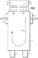
- FIG. 1 a schematic top view is shown a “loop” type glass furnace 1 of substantially rectangular shape, comprising two lateral charging zones 4 and 5 of the glass, in the part back of the oven, the molten glass flowing in the direction of arrow 10 towards channels 2 and 3 themselves connected to power supplies (or feeders) of glass forming machines.
- Preheated air in the adjacent regenerator is injected into opening 8 (or "port") and burns with the fuel injected through the injectors 9, forming a U-shaped flame shown diagrammatically by the arrow 10, the fumes of which escape through the opening 11 and heat the adjacent regenerator. Every 20 to 30 minutes, we cause a reversing the system using preheated air in the regenerator adjacent to opening 11 and fuel injected into injectors 12 forming a U-shaped flame, the fumes of which are discharged through the opening 8 and heats the regenerator adjacent to this opening 8.
- FIG. 2 represents an exemplary embodiment of the invention.
- the same elements as those in FIG. 1 bear the same references.
- This method kept the oven in production during the repair of the recuperators.
- Two oxygen lances 37 are installed at the below opening 25. They are surrounded by three gas injectors natural 28. Oxygen lances 37 and natural gas injectors 28 are located in different planes. The natural gas injectors plan is located above that of the oxygen lances so as to form a oxidizing atmosphere, in this case.
- the glass on the contrary, must be melted under an atmosphere reducing, we will place the gas injectors below the injectors oxygen. But it is better, in any case, to have speeds injecting oxidant and fuel which are not too different, in order to avoid rapid mixing (turbulence) and on the contrary obtain a staged combustion.
- the ratio of the oxidizer and fuel will preferably be greater than 1, more preferably between 1 and 2.
- Oxygen is introduced into the furnace under subsonic conditions according to an angle between -15 ° and + ° 15 ° approximately. It is understood that it is also possible to install lances or injectors in the same plan.
- a third oxygen lance 38 is installed near the orifice 21 for the outlet of the fumes from the oven so as to complete the combustion and avoid burning carbon monoxide in the chimney gas evacuation.
- Natural gas is introduced with a speed of preferably between 10 and 150 m / s.
- the oxygen injection is done from preferably in subsonic mode in order to avoid on the one hand overheating on the root of the flame, and secondly the development of hot spots on the wall of the oven located in front of this flame, hot spot which would then be due to too great a pulse of the flame.
- two burners positioned substantially horizontally and slightly oriented towards the charging area. (By "slightly” is meant an angle between approximately 0 ° and 10 °).
- the flame developed at the top of the oven covers more than two thirds from the surface of the glass bath. It is long and bright thanks to a incomplete combustion resulting from cracking of natural gas in the flame in the initial part of the combustion, followed by a re-burning of the carbon particles thus generated.
- the energy and oxygen brought by two burners located in the refining area allow to bring the additional energy required for combustion and to maintain shape loop the resulting flame over the bath. In this way, a Maximum coverage of the bath surface is achieved.
- the combustion in the oven is asymmetrical, that is to say that the coefficient Ks evolves along the flame.
- This combustion is preferably "stepped" so as to lengthen the flame for a cover maximum of the surface of the molten bath.
Landscapes
- Chemical & Material Sciences (AREA)
- Engineering & Computer Science (AREA)
- Combustion & Propulsion (AREA)
- Materials Engineering (AREA)
- Organic Chemistry (AREA)
- Glass Melting And Manufacturing (AREA)
Description
La présente invention concerne des fours de verre, notamment des fours boucles à récupérateur ou à régénérateurs. Elle concerne plus particulièrement un procédé et un système pour four de verre, notamment un four boucle muni d'un récupérateur permettant de conserver la productivité du four de verre lors d'une défaillance du récupérateur ou du régénérateur et pendant toute la durée de sa réparation.The present invention relates to glass furnaces, in particular loop furnaces with recuperator or regenerator. It concerns more particularly a method and a system for a glass furnace, in particular a loop furnace fitted with a recuperator to maintain productivity glass furnace in the event of a recuperator or regenerator failure and for the duration of its repair.
Un four de verre est habituellement alimenté en énergie par l'intermédiaire, notamment, de brûleurs dits "aéro-combustibles" dans lesquels on injecte un mélange d'air et de combustible tel que gaz naturel, fioul, etc. Ces fours possèdent habituellement au moins un récupérateur ou régénérateur, qui permet de préchauffer l'air avant de l'injecter dans les brûleurs. Lorsque le récupérateur ou régénérateur du four est défaillant ou endommagé, ce four étant normalement chauffé avec des brûleurs à l'air, il n'est plus possible de préchauffer suffisamment l'air injecté dans ces brûleurs et la consommation d'énergie dans les brûleurs augmente. Quelquefois l'énergie apportée par la flamme n'est plus suffisante et on constate des points froids sur ou dans le bain de verre, très préjudiciables à la qualité du verre produit et au rendement du four.A glass furnace is usually supplied with energy by through, in particular, so-called "air-fuel" burners in which are injected with a mixture of air and fuel such as natural gas, fuel oil, etc. These ovens usually have at least one recuperator or regenerator, which preheats the air before injecting it into the burners. When the furnace recuperator or regenerator fails or damaged, this oven being normally heated with air burners, it is no longer possible to sufficiently preheat the air injected into these burners and the energy consumption in the burners increases. Sometimes the energy provided by the flame is no longer sufficient and we finds cold spots on or in the glass bath, very detrimental to the quality of the glass produced and the efficiency of the furnace.
La réparation d'un récupérateur dans un four peut demander plusieurs semaines ou plusieurs mois et il est nécessaire pendant cette période de réparation de continuer la production de verre dans le four. Le problème posé consiste donc à trouver un moyen pour remplacer la fonction du récupérateur tout en utilisant si possible moins d'énergie que lorsque le four est en fonctionnement normal avec son récupérateur.Repairing a recuperator in an oven may require several weeks or several months and it is necessary during this repair period to continue the production of glass in the furnace. The problem is therefore to find a way to replace the function of the recuperator while using, if possible, less energy than when the oven is in normal operation with its recuperator.
Les fours de verre peuvent être classés dans différentes catégories selon, en général, le type de verre fabriqué et son utilisation en aval du four de fusion et d'affinage. Les fours de verre pour la fabrication de fibres de verre comportent généralement un ou plusieurs récupérateurs qui récupèrent la chaleur des fumées par échange thermique avec l'air entrant dans le four pour alimenter les brûleurs. Ces fours sont en général des fours dans lesquels le chauffage/fusion de la charge de verre s'effectue grâce à une pluralité de brûleurs disposés dans les parois latérales du four. Glass furnaces can be classified into different categories according to, in general, the type of glass manufactured and its use in downstream of the melting and refining furnace. Glass furnaces for the manufacture of glass fibers generally have one or more recuperators which recover the heat of the fumes by heat exchange with the incoming air in the oven to supply the burners. These ovens are generally ovens in which the heating / melting of the glass charge takes place thanks to a plurality of burners arranged in the side walls of the oven.
Un autre type de four est constitué par les fours dits à régénérateurs et qui comportent au moins deux régénérateurs, fonctionnant alternativement dans le temps :Another type of oven is the so-called ovens regenerators and which comprise at least two regenerators, operating alternately in time:
Les fumées avant leur évacuation à l'atmosphère, traversent ces régénérateurs et cèdent une partie de la chaleur à des parois réfractaires disposées en chicane dans le régénérateur. Toutes les 20 à 30 minutes, on commute en général les brûleurs et les régénérateurs de manière à ce que le régénérateur auparavant traversé par les fumées chaudes des brûleurs soit traversé par l'air frais qui alimente les brûleurs et vice-versa. Cet air extérieur frais est ainsi chauffé au contact des parois du régénérateur.The fumes, before being discharged into the atmosphere, pass through these regenerators and transfer part of the heat to refractory walls arranged in a baffle in the regenerator. Every 20 to 30 minutes, we generally switches the burners and regenerators so that the regenerator previously crossed by the hot fumes from the burners either the fresh air which feeds the burners and vice versa. This air the cool exterior is thus heated in contact with the walls of the regenerator.
Il existe essentiellement deux types de fours à régénérateurs : ceux du type à brûleurs transversaux qui comportent des séries de brûleurs dans les parois latérales du four avec, en face de chacun d'eux, un régénérateur, et ceux du type à boucle qui comportent deux régénérateurs adjacents situés dans la partie amont du four (par rapport à l'écoulement de la charge de verre), avec généralement un ou plusieurs injecteurs de combustible situés sous l'ouverture de chaque régénérateur donnant dans le four, de sorte que les fumées des flammes créées par la combustion du combustible et de l'air préchauffé sont récupérées dans l'autre régénérateur et vice-versa lors de la commutation d'un système de brûleurs à l'autre (toutes les 20 à 30 minutes).There are basically two types of regenerator ovens: those of the transverse burner type which include series of burners in the side walls of the oven with, opposite each of them, a regenerator, and those of the loop type which have two regenerators adjacent located in the upstream part of the furnace (in relation to the flow of glass charge), usually with one or more injectors fuel located under the opening of each regenerator giving into the oven, so that the smoke from the flames created by the combustion of the fuel and preheated air are recovered in the other regenerator and vice versa when switching from one burner system to another (every 20 to 30 minutes).
La présente invention concerne essentiellement ces derniers fours de type boucle à régénérateurs.The present invention relates essentially to the latter loop type furnaces with regenerators.
Plus de détails sur les fours de verre peuvent être trouvés par exemple dans l'ouvrage intitulé "Glass Furnaces - Design, Construction and Operation" - Society of Glass Technology - 1987 - de Wolfgang Trier.More details on glass furnaces can be found by example in the book "Glass Furnaces - Design, Construction and Operation "- Society of Glass Technology - 1987 - by Wolfgang Trier.
De nombreux documents de l'art antérieur décrivent l'utilisation de brûleurs oxycombustibles dans les fours de verre, soit en complément des brûleurs existants, soit en remplacement desdits brûleurs.Many documents of the prior art describe the use of oxy-fuel burners in glass furnaces, or in addition to existing burners, either to replace said burners.
Il est connu, par exemple, de la demande européenne EP-A-0.447.300 au nom de la Demanderesse, un procédé de fusion et d'affinage d'un four de verre de type boucle dans lequel on rajoute au moins un brûleur de type oxycombustible dans la zone d'affinage du verre, ledit brûleur étant du type dans lequel on réalise une combustion dite "pulsée" sur le combustible ou le comburant de manière à réduire la production de NOx dans les fumées.It is known, for example, from European demand EP-A-0.447.300 in the name of the Applicant, a process for merging and refining of a loop type glass furnace in which at least one is added an oxy-fuel type burner in the glass refining area, said burner being of the type in which a so-called "pulsed" combustion is carried out on the fuel or oxidizer so as to reduce the production of NOx in the fumes.
Le brevet US-A-5.116.399 décrit un procédé de fusion de verre dans un four boucle qui comporte un seul brûleur additionnel oxycombustible situé dans la zone d'affinage du verre au milieu de la paroi frontale du four de verre, orienté vers la masse fondue, de manière à maintenir la matière non fondue en-deçà sensiblement de la rangée des bouillonneurs qui séparent la zone de fusion de la zone d'affinage. Dans ce but, les gaz de la flamme issue de ce brûleur additionnel doivent avoir une vitesse au moins égale à 100 m/s, ce qui en fait une flamme dite "à haute impulsion" et présentant notamment pour inconvénient majeur lorsqu'elle est projetée en limite de la masse fondue, de provoquer l'envoi des particules de verre non fondu.US-A-5,116,399 describes a process for melting glass in a loop oven which includes a single additional oxy-fuel burner located in the glass refining area in the middle of the front wall of the glass, oriented towards the melt, so as to maintain the material not fondue substantially below the row of bubblers that separate the refining zone of the refining zone. For this purpose, the flame gases from this additional burner must have a speed at least equal to 100 m / s, making it a so-called "high impulse" flame with especially for major drawback when it is projected at the limit of the molten mass, causing the sending of particles of unmelted glass.
Parmi les documents cités ci-dessus et concernant les fours de verre du type boucle à régénérateurs, aucun n'est relatif au fonctionnement d'un tel four sans régénérateurs, c'est-à-dire qu'aucun ne concerne en particulier le problème du fonctionnement de ce four pendant la réparation des régénérateurs.Among the documents cited above and relating to glass of the loop type with regenerators, none relates to operation of such an oven without regenerators, that is to say that none of them concerns especially the problem of the operation of this oven during repair regenerators.
De même, le document publicitaire intitulé "Glassman Europe '93-Presented at Glassman Europe '93- Lyon - France - April 28, 1993" par G.B.Tuson, H. Kobayashi et E.J. Lawers est totalement muet sur ce problème.Likewise, the advertising document entitled "Glassman Europe '93 -Presented at Glassman Europe '93 - Lyon - France - April 28, 1993 "by G.B. Tuson, H. Kobayashi and E.J. Lawers is completely silent on this problem.
En particulier, le problème que les inventeurs ont eu à résoudre, après avoir songé à utiliser des flammes dont le comburant comporte plus d'oxygène que l'air et de préférence plus de 50 % vol. d'oxygène, consistait à maintenir sa forme de boucle à la flamme, c'est-à-dire chauffer sensiblement toute la surface du bain de verre : autant cette forme de boucle est relativement facile à réaliser lorsqu'on utilise de l'air, autant cela s'avère difficile lorsque le comburant est de l'oxygène pur ou sensiblement pur (c'est-à-dire ayant de préférence plus de 88 % vol. d'oxygène) et que la vitesse d'injection de l'oxygène ou du gaz comburant reste faible et ne dépasse pas en général 60 m/s (par exemple dans le cas d'oxygène fourni soit à partir d'un réservoir d'oxygène liquide, soit à partir d'un système d'adsorption sous faible pression de type VSA (Vacuum Switch Adsorption) mais que la vitesse du gaz combustible est élevée (c'est-à-dire en particulier lorsque le rapport des vitesses du combustible et du comburant est supérieur à 1). La vitesse du gaz combustible, souvent supérieure à 100 m/s, provoque alors un mélange rapide comburant/ combustible et donc un racourcissement de la flamme qui perd alors sa forme de boucle. (Plus la vitesse du gaz combustible est supérieure à celle du gaz comburant, plus le mélange des deux a tendance à se faire rapidement).In particular, the problem that the inventors had to solve, after considering using flames with more oxidizer of oxygen than air and preferably more than 50% vol. oxygen, consisted maintain its flame loop shape, i.e. heat substantially the entire surface of the glass bath: this form of loop is relatively easy to perform when using air, it turns out difficult when the oxidant is pure or substantially pure oxygen (i.e. preferably having more than 88% vol. of oxygen) and that the oxygen or oxidant gas injection rate remains low and does not generally not exceed 60 m / s (for example in the case of oxygen supplied either from a liquid oxygen tank or from a system VSA (Vacuum Switch Adsorption) type low pressure adsorption but that the speed of the combustible gas is high (i.e. in particular when the ratio of fuel and oxidizer speeds is greater than 1). The speed of combustible gas, often greater than 100 m / s, then causes a rapid oxidant / fuel mixture and therefore a shortening of the flame which then loses its loop form. (The more speed of the combustible gas is higher than that of the oxidizing gas, the higher the mixing the two tends to happen quickly).
Le procédé selon l'invention pour la réalisation d'une flamme en
forme de boucle dans un four de verre de type "boucle" comportant dans sa
partie arrière une zone de fusion du verre chauffée au moyen d'au moins un
premier brûleur alimenté en combustible et en comburant comportant plus
de 50 % vol. d'oxygène, et dans sa partie avant une zone d'affinage du
verre, procédé dans lequel on définit un coefficient de stoechiométrie Ks de
la flamme dans une zone du four, égal au rapport :
Selon un autre aspect de l'invention, le procédé de transformation
temporaire d'un four de verre du type "à boucle" comportant des moyens de
récupération de la chaleur des gaz brûlés, au moins un brûleur aéro-combustible
placé dans la partie arrière du four et créant une flamme au-dessus
du bain de verre ayant la forme d'une boucle s'étendant au-dessus
de la zone de fusion du verre et de la zone d'affinage jusqu'à proximité de la
paroi avant du four, délimitant la zone d'affinage du verre, puis revenant au-dessus
de la zone de fusion vers la partie arrière du four, au moins deux
zones d'enfournement du verre non fondu située à proximité de la paroi
arrière du four et dans la zone de fusion du verre, est caractérisé en ce que
lors de la réfection des moyens de récupération de la chaleur des gaz
brûlés, lesdits moyens de récupéation sont fermés de manière à éviter tout
passage de fumées, en ce qu'au moins un premier brûleur alimenté en
combustible et comburant comportant au moins 50 % volume d'oxygène, est
installé à la place d'au moins un brûleur aérocombustible existant, en ce que
les fumées sont évacuées par l'intermédiaire de l'une au moins des zones
d'enfournement de verre, en ce qu'un moyen d'injection alimenté en
combustible et comburant comportant au moins 50 % volume en oxygène,
est installé dans la zone d'affinage du verre et en ce qu'au moins un moyen
d'injection de gaz comburant comportant au moins 50 % d'oxygène est
installé dans la paroi latérale du four située dans la zone de fusion à
proximité de la zone d'évacuation des fumées, de manière à créer une
flamme ayant une forme de boucle dont la valeur du coefficient de
stoechiométrie Ks dans une zone du four :
Selon un mode préférentiel de réalisation, l'invention est caractérisée en ce que le gaz comburant est de l'oxygène d'une pureté égale ou supérieure à 88 % volume, injecté à une vitesse comprise entre 10 m/s et 150 m/s.According to a preferred embodiment, the invention is characterized in that the oxidizing gas is oxygen of purity equal to or greater than 88% volume, injected at a speed between 10 m / s and 150 m / s.
Selon un autre mode de réalisation, l'invention est caractérisée en ce que le gaz comburant est produit est par un appareil de séparation des gaz de l'air à adsorption du type PSA ou VSA produisant de l'oxygène.According to another embodiment, the invention is characterized in what the oxidizing gas is produced is by an apparatus for separation of PSA or VSA type adsorption air gas producing oxygen.
Selon une variante de réalisation, l'invention est caractérisée en ce que le rapport des vitesses d'injection des gaz combustible et gaz comburant lors de leur injection dans le four est supérieur ou égal à 1.According to an alternative embodiment, the invention is characterized in what the ratio of fuel gas and gas injection speeds oxidizer when injected into the furnace is greater than or equal to 1.
Selon un autre mode de réalisation, l'invention est caractérisée en ce que le rapport de stoechiométrie Ks dans la zone d'affinage du four est compris entre environ 0,5 et 0,8. According to another embodiment, the invention is characterized in what the stoichiometric ratio Ks in the furnace refining area is between about 0.5 and 0.8.
Selon un mode préférentiel de réalisation, l'invention est caractérisée en ce que le rapport de stoechiométrie Ks dans la zone d'affinage du four est de l'ordre d'environ 1,3.According to a preferred embodiment, the invention is characterized in that the stoichiometric ratio Ks in the area refining of the furnace is of the order of approximately 1.3.
De préférence, la quantité d'oxygène dans les fumées après injection de gaz comburant est égale à environ 1,5 % en volume.Preferably, the amount of oxygen in the fumes after injection of oxidizing gas is approximately 1.5% by volume.
De préférence également, le rapport Ks dans la zone de fusion est d'environ 0,65.Also preferably, the ratio Ks in the melting zone is approximately 0.65.
De façon préférentielle, la quantité d'oxygène en volume injectée dans la zone de fusion du verre, à l'exception de la zone d'évacuation des fumées est d'environ 40 % la quantité totale d'oxygène en volume injectée dans le four.Preferably, the quantity of oxygen by volume injected in the glass melting zone, with the exception of the evacuation zone for smoke is around 40% the total amount of oxygen by volume injected in the oven.
De préférence, la quantité d'oxygène en volume injectée dans la zone d'affinage du verre est d'environ 50 % la quantité totale d'oxygène en volume injectée dans le four.Preferably, the quantity of oxygen by volume injected into the glass refining area is about 50% the total amount of oxygen in volume injected into the oven.
Selon un autre mode de réalisation de l'invention, la quantité d'oxygène en volume injectée dans la zone d'évacuation des fumées est d'environ 10 % la quantité totale d'oxygène en volume injectée dans le four.According to another embodiment of the invention, the quantity of oxygen by volume injected into the smoke evacuation zone is about 10% of the total quantity of oxygen by volume injected into the oven.
Il est également possible que, selon l'invention, un combustible, généralement sous forme gazeuse, soit envoyé dans le four avec le verre non fondu et la quantité de gaz comburant injectée dans le four est ajustée de manière à maintenir sensiblement les rapports stoechiométriques.It is also possible that, according to the invention, a fuel, usually in gaseous form, either sent into the oven with the glass not melted and the quantity of oxidizing gas injected into the oven is adjusted so as to substantially maintain the stoichiometric ratios.
Le coefficient de stoechiométrie Ks d'une flamme dans une zone
du four est défini comme suit :
Le volume d'oxygène réel est le volume d'oxygène réellement ajouté dans la zone considérée (fusion, affinage) par l'intermédiaire d'un brûleur et/ou d'une ou plusieurs lances.The actual oxygen volume is the actual oxygen volume added in the zone considered (fusion, refining) via a burner and / or one or more lances.
Le volume d'oxygène stoechiométrique est défini comme étant le volume d'oxygène nécessaire à la combustion complète du combustible injecté dans la zone considérée par l'intermédiaire d'un ou plusieurs brûleurs ou provenant de la zone précédant la zone considérée. Tous ces volumes sont bien entendu définis dans des conditions similaires, de préférence des conditions normales de température et de pression (20°C -1 atmosphère).The stoichiometric oxygen volume is defined as the volume of oxygen required for complete combustion of the fuel injected into the area under consideration via one or more burners or coming from the zone preceding the zone considered. All these volumes are of course defined under similar conditions, preferably normal temperature and pressure conditions (20 ° C -1 atmosphere).
Le rapport de combustion stoechiométrique pour le gaz naturel est d'environ de 2 m3 d'oxygène par m3 de gaz naturel. Pour le fioul lourd, ce rapport est d'environ de 2,4 m3 d'oxygène par m3 de fioul lourd. D'une façon générale pour un combustible de 10 kWh de PCI (pouvoir combustible inférieur), il faut sensiblement 2 m3 d'oxygène.The stoichiometric combustion ratio for natural gas is approximately 2 m 3 of oxygen per m 3 of natural gas. For heavy fuel oil, this ratio is approximately 2.4 m 3 of oxygen per m 3 of heavy fuel oil. Generally, for a fuel of 10 kWh of PCI (lower fuel power), approximately 2 m 3 of oxygen is required.
L'invention sera mieux comprise à l'aide des exemples de réalisation suivants, donnés à titre non limitatif, conjointement avec les figures, qui représentent :
- la figure 1, un schéma conventionnel d'un four à boucle à récupérateur pour produire du verre, selon l'art antérieur,
- la figure 2 représente un mode de fonctionnement du four de la figure 1 en l'absence de récupérateur, dans lequel la combustion du four est une combustion entièrement à l'oxygène, selon l'invention.
- FIG. 1, a conventional diagram of a recuperator loop furnace for producing glass, according to the prior art,
- FIG. 2 represents an operating mode of the oven of FIG. 1 in the absence of a recuperator, in which the combustion of the oven is combustion entirely with oxygen, according to the invention.
Sur la figure 1, est représentée une vue schématique de dessus
d'un four de verre de type "boucle" 1 de forme sensiblement rectangulaire,
comportant deux zones d'enfournement latéral 4 et 5 du verre, dans la partie
arrière du four, le verre fondu s'écoulant dans le sens de la flèche 10 vers
les canaux 2 et 3 eux-mêmes reliés à des alimentations (ou feeders) des
machines de formage du verre.In Figure 1, a schematic top view is shown
a “loop”
Dans la paroi arrière du four sont en général disposés deux
ensembles 6 et 7, généralement identiques comportant chacun une
ouverture 8, 11, en communication avec les régénérateurs (non représentés
sur la figure) et une série d'injecteurs de combustible 9, en général du gaz
naturel ou éventuellement du fioul pulvérisé.In the rear wall of the oven are generally arranged two
De l'air préchauffé dans le régénérateur adjacent est injecté dans
l'ouverture 8 (ou "port") et brûle avec le combustible injecté à travers les
injecteurs 9, formant une flamme en forme de U schématisée par la
flèche 10, dont les fumées s'échappent par l'ouverture 11 et chauffent le
régénérateur adjacent. Toutes les 20 à 30 minutes, on provoque une
inversion du système en utilisant de l'air préchauffé dans le régénérateur
adjacent à l'ouverture 11 et du combustible injecté dans les injecteurs 12
formant une flamme en U dont les fumées sont évacuées par l'ouverture 8 et
réchauffe le régénérateur adjacent à cette ouverture 8. Preheated air in the adjacent regenerator is injected into
opening 8 (or "port") and burns with the fuel injected through the
injectors 9, forming a U-shaped flame shown diagrammatically by the
La figure 2 représente un exemple de réalisation de l'invention. Sur la figure 2, les mêmes éléments que ceux de la figure 1 portent les mêmes références.FIG. 2 represents an exemplary embodiment of the invention. In FIG. 2, the same elements as those in FIG. 1 bear the same references.
Entre les trois injecteurs de combustible 28 sont placées deux
lances à oxygène 37. Pour compléter la combustion, deux brûleurs
oxycombustibles 39 et 40 sont placés dans la zone d'affinage du verre, au-delà
des bouillonneurs 49. Enfin une lance à oxygène 38 est prévue avant et
à proximité de l'évacuation des fumées 21.Between the three
Dans cette configuration des lances à oxygène 37 et des brûleurs
oxycombustibles 39 et 40 d'une puissance nominale de 500 kW chacun ont
été utilisés de manière à réaliser cette conversion du four sans son
récupérateur. Une évacuation des fumées a été installée à la place d'une
des ouvertures d'enfournement du verre pour permettre d'isoler le ou les
récupérateurs en vue de réparations.In this configuration of the oxygen lances 37 and the burners
oxy-
Cette méthode a permis de maintenir le four en production pendant la réparation des récupérateurs.This method kept the oven in production during the repair of the recuperators.
Des lances à oxygène 37 au nombre de deux sont installées au
dessous de l'ouverture 25. Elles sont entourées par trois injecteurs de gaz
naturel 28. Les lances à oxygène 37 et les injecteurs de gaz naturel 28 sont
situés dans des plans différents. Le plan des injecteurs de gaz naturel est
situé au-dessus de celui des lances à oxygène de manière à former une
atmosphère oxydante, dans le cas présent.Two oxygen lances 37 are installed at the
Si le verre, au contraire, doit être fondu sous atmosphère réductrice, on placera les injecteurs de gaz au-dessous des injecteurs d'oxygène. Mais il est préférable, dans tous les cas, d'avoir des vitesses d'injection de comburant et de combustible qui ne soient pas trop différentes, afin d'éviter un mélange rapide (turbulences) et obtenir au contraire une combustion étagée. Cependant le rapport des vitesses du comburant et du combustible sera de préférence supérieur à 1, plus préférentiellement compris entre 1 et 2.If the glass, on the contrary, must be melted under an atmosphere reducing, we will place the gas injectors below the injectors oxygen. But it is better, in any case, to have speeds injecting oxidant and fuel which are not too different, in order to avoid rapid mixing (turbulence) and on the contrary obtain a staged combustion. However, the ratio of the oxidizer and fuel will preferably be greater than 1, more preferably between 1 and 2.
L'oxygène est introduit dans le four en régime subsonique selon un angle compris entre -15° et +°15° environ. Il est bien entendu qu'il est également possible d'installer des lances ou des injecteurs dans le même plan. Oxygen is introduced into the furnace under subsonic conditions according to an angle between -15 ° and + ° 15 ° approximately. It is understood that it is also possible to install lances or injectors in the same plan.
Une troisième lance à oxygène 38 est installée à proximité de
l'orifice 21 de sortie des fumées du four de manière à compléter la
combustion et d'éviter de brûler le monoxyde de carbone dans la cheminée
d'évacuation des gaz. Le gaz naturel est introduit avec une vitesse de
préférence comprise entre 10 et 150 m/s. L'injection d'oxygène se fait de
préférence en régime subsonique afin d'éviter d'une part une surchauffe à la
racine de la flamme, et d'autre part le développement de points chauds sur
le mur du four situé en face de cette flamme, point chaud qui serait dû alors
à une impulsion trop grande de la flamme.A
Dans la zone d'affinage du verre sont installés de préférence deux brûleurs positionnés sensiblement horizontalement et légèrement orientés vers la zone d'enfournement. (Par "légèrement", on entend un angle compris entre environ 0° et 10°).In the glass refining area are preferably installed two burners positioned substantially horizontally and slightly oriented towards the charging area. (By "slightly" is meant an angle between approximately 0 ° and 10 °).
Le réglage de la combustion s'effectue de la manière indiquée
dans le tableau 1, c'est-à-dire qu'environ 60 % de la puissance calorifique
est concentré dans la zone de fusion (qui s'étend jusqu'aux bouillonneurs
49) avec 40 % en volume de l'oxygène total injecté dans cette zone de
fusion, avec un coefficient Ks de l'ordre de 0,65 (compris entre 0,5 et 0,8),
40 % de la puissance calorifique concentrée dans la zone d'affinage avec un
coefficient Ks = 1,3 (compris entre 0,8 et 1,5) et 50 % vol. de l'oxygène total
(ou comburant total) injecté dans cette zone d'affinage et aucune puissance
concentrée sur la zone d'évacuation des fumées, mais avec environ 10 % en
volume de l'oxygène total distribué dans le four, injecté via la lance 38, à
proximité de l'ouverture d'évacuation des fumées afin d'éliminer les gaz
combustibles et polluants avant évacuation des fumées. (Plus généralement
selon le ratio complémentaire d'oxygène tel que défini ci-dessus).The combustion adjustment is carried out as indicated
in table 1, i.e. about 60% of the heat output
is concentrated in the melting zone (which extends to the bubblers
49) with 40% by volume of the total oxygen injected into this zone of
fusion, with a coefficient Ks of the order of 0.65 (between 0.5 and 0.8),
40% of the calorific power concentrated in the refining zone with a
coefficient Ks = 1.3 (between 0.8 and 1.5) and 50% vol. total oxygen
(or total oxidizer) injected into this refining zone and no power
concentrated in the smoke evacuation zone, but with around 10%
volume of total oxygen distributed in the oven, injected via the
La flamme développée en tête du four couvre plus des deux tiers de la surface du bain de verre. Elle est longue et lumineuse grâce à une combustion incomplète résultant d'un craquage du gaz naturel dans la flamme dans la partie initiale de la combustion, suivi par un rebrûlage des particules de carbone ainsi générées. L'énergie et l'oxygène amenés par les deux brûleurs situés dans la zone d'affinage permettent d'apporter le complément d'énergie nécessaire à la combustion et de maintenir la forme de boucle de la flamme résultante au-dessus du bain. De cette manière, une couverture maximum de la surface du bain est réalisée. The flame developed at the top of the oven covers more than two thirds from the surface of the glass bath. It is long and bright thanks to a incomplete combustion resulting from cracking of natural gas in the flame in the initial part of the combustion, followed by a re-burning of the carbon particles thus generated. The energy and oxygen brought by two burners located in the refining area allow to bring the additional energy required for combustion and to maintain shape loop the resulting flame over the bath. In this way, a Maximum coverage of the bath surface is achieved.
La distribution de l'énergie et des rapports de stoechiométrie Ks
dans le four sont résumés dans le tableau 1 ci-après.
La combustion dans le four est dissymétrique, c'est-à-dire que le coefficient Ks évolue le long de la flamme. Cette combustion est de préférence "étagée" de manière à rallonger la flamme pour une couverture maximum de la surface du bain en fusion.The combustion in the oven is asymmetrical, that is to say that the coefficient Ks evolves along the flame. This combustion is preferably "stepped" so as to lengthen the flame for a cover maximum of the surface of the molten bath.
Grâce aux résultats obtenus, on a constaté que la consommation spécifique du four a baissé de 17 % environ malgré une tirée du four plus faible tandis que la qualité de verre réalisée est substantiellement identique à celle réalisée avant modification du four.Thanks to the results obtained, it was found that consumption specific furnace performance decreased by around 17% despite a further low while the quality of glass produced is substantially identical to that carried out before modification of the oven.
Claims (13)
- Process for the production of a loop-shaped flame in a glass furnace comprising in its rear part a glass melting zone heated by means of at least one first port fed with fuel and with oxidizer comprising more than 50 vol% of oxygen and, in its front part, a glass refining zone, in which process a stoichiometry coefficient Ks of the flame in a zone of the furnace is defined, equal to the ratio:
- Process for temporary conversion of a glass furnace of the "end-fired" type comprising means for recovery of the heat of the burnt gases, at least one air-fuel port placed in the rear part of the furnace and creating a flame above the bath of glass which has the shape of a loop extending above the glass melting zone and the refining zone as far as proximity to the front wall of the furnace, bounding the glass refining zone, then returning above the melting zone towards the rear part of the furnace, at least two zones for charging unmelted glass, situated in proximity to the rear wall of the furnace and in the glass melting zone, characterized in that during the repair to the means of recovery of the heat of the burnt gases the said means of recovery are closed so as to avoid any flow of fumes, in that at least one first port fed with fuel and oxidizer comprising at least 50 volume % of oxygen is installed in the place of at least one existing air-fuel port, in that the fumes are discharged through the intermediacy of at least one of the zones for charging glass, in that a means of injection fed with fuel and oxidizer comprising at least 50 volume % as oxygen is installed in the glass refining zone and in that at least one means of injecting oxidizer gas comprising at least 50 % of oxygen is installed in the side wall of the furnace situated in the melting zone in proximity to the fume discharge zone, so as to create a flame which is loop-shaped, in which the value of the stoichiometry coefficient Ks in a zone of the furnace:
- Process for temporary conversion of a glass furnace of the "end-fired" type according to Claim 2, characterized in that the oxidizer gas is oxygen of a purity equal to or higher than 88 volume %, injected at a speed of between 10 and 150 m/s.
- Process for temporary conversion of a glass furnace of the "end-fired" type according to Claim 2 or 3, characterized in that the oxidizer gas is produced by an apparatus for separating the gases of air with adsorption of the PSA or VSA type, producing oxygen.
- Process according to one of Claims 1 to 4, characterized in that the ratio of the fuel gas/oxidizer gas injection speeds during their injection into the furnace is higher than or equal to 1.
- Process according to one of Claims 1 to 5, characterized in that the stoichiometry ratio Ks in the refining zone of the furnace is between approximately 0.5 and 0.8.
- Process according to one of Claims 1 to 6, characterized in that the stoichiometry ratio Ks in the refining zone of the furnace is of the order of approximately 1.3.
- Process according to one of Claims 1 to 7, characterized in that the quantity of oxygen in the fumes after injection of oxidizer gas is equal to approximately 1.5 % by volume.
- Process according to one of Claims 1 to 8, characterized in that the ratio Ks in the melting zone is approximately 0.65.
- Process according to one of Claims 1 to 9, characterized in that the quantity of oxygen by volume injected into the glass melting zone, with the exception of the fume discharge zone, is approximately 40 % of the total quantity of oxygen by volume injected into the furnace.
- Process according to one of Claims 1 to 10, characterized in that the quantity of oxygen by volume injected into the glass refining zone is approximately 50 % of the total quantity of oxygen by volume injected into the furnace.
- Process according to one of Claims 1 to 11, characterized in that the quantity of oxygen by volume injected into the fume discharge zone is approximately 10 % of the total quantity of oxygen by volume injected into the furnace.
- Process according to one of Claims 1 to 12, characterized in that a fuel, generally in gaseous form, is sent into the furnace with the unmelted glass and the quantity of oxidizer gas injected into the furnace is adjusted so as to maintain substantially the stoichiometric ratios.
Applications Claiming Priority (2)
| Application Number | Priority Date | Filing Date | Title |
|---|---|---|---|
| FR9606013 | 1996-05-14 | ||
| FR9606013 | 1996-05-14 |
Publications (2)
| Publication Number | Publication Date |
|---|---|
| EP0807608A1 EP0807608A1 (en) | 1997-11-19 |
| EP0807608B1 true EP0807608B1 (en) | 2001-12-12 |
Family
ID=9492133
Family Applications (1)
| Application Number | Title | Priority Date | Filing Date |
|---|---|---|---|
| EP97400967A Expired - Lifetime EP0807608B1 (en) | 1996-05-14 | 1997-04-29 | Process for repairing a furnace using an oxygen-fired auxiliary burner |
Country Status (5)
| Country | Link |
|---|---|
| US (1) | US5855639A (en) |
| EP (1) | EP0807608B1 (en) |
| JP (1) | JP4112650B2 (en) |
| DE (1) | DE69708965T2 (en) |
| ES (1) | ES2169843T3 (en) |
Families Citing this family (9)
| Publication number | Priority date | Publication date | Assignee | Title |
|---|---|---|---|---|
| FR2757845B1 (en) * | 1996-12-31 | 1999-01-29 | Air Liquide | PROCESS FOR IMPROVING THE THERMAL PROFILE OF GLASS OVENS AND GLASS MELTING OVEN FOR IMPLEMENTING IT |
| US6113386A (en) * | 1998-10-09 | 2000-09-05 | North American Manufacturing Company | Method and apparatus for uniformly heating a furnace |
| CA2323032A1 (en) * | 1999-10-18 | 2001-04-18 | Air Products And Chemicals, Inc. | Method and apparatus for backing-up oxy-fuel combustion with air-fuel combustion |
| US6519973B1 (en) | 2000-03-23 | 2003-02-18 | Air Products And Chemicals, Inc. | Glass melting process and furnace therefor with oxy-fuel combustion over melting zone and air-fuel combustion over fining zone |
| US6436337B1 (en) * | 2001-04-27 | 2002-08-20 | Jupiter Oxygen Corporation | Oxy-fuel combustion system and uses therefor |
| FR2909995B1 (en) * | 2006-12-18 | 2010-04-23 | Saint Gobain Rech | LOOP OVEN FOR FIBER GLASS |
| US20130180289A1 (en) * | 2011-04-07 | 2013-07-18 | Rainer Mieth | Method and device for melting meltable stock |
| CN106277718B (en) * | 2016-08-19 | 2019-03-15 | 巨石集团有限公司 | A kind of glass fibre tank furnace glass metal channel heating means |
| CN110615598B (en) * | 2019-09-27 | 2020-06-23 | 湖南巨强再生资源科技发展有限公司 | Energy-efficient horse-shoe flame smelting pot |
Family Cites Families (9)
| Publication number | Priority date | Publication date | Assignee | Title |
|---|---|---|---|---|
| US2800175A (en) * | 1949-06-11 | 1957-07-23 | Libbey Owens Ford Glass Co | Firing tank furnaces |
| US3592623A (en) * | 1969-04-04 | 1971-07-13 | Air Reduction | Glass melting furnace and method of operating it |
| SE463512B (en) * | 1989-04-17 | 1990-12-03 | Aga Ab | SET AND MOLDING FOR PRODUCING GLASS |
| FR2659729B1 (en) * | 1990-03-16 | 1992-06-05 | Air Liquide | PROCESS FOR MELTING AND REFINING A LOAD. |
| US5116399A (en) * | 1991-04-11 | 1992-05-26 | Union Carbide Industrial Gases Technology Corporation | Glass melter with front-wall oxygen-fired burner process |
| US5139558A (en) * | 1991-11-20 | 1992-08-18 | Union Carbide Industrial Gases Technology Corporation | Roof-mounted auxiliary oxygen-fired burner in glass melting furnace |
| US5242296A (en) * | 1992-12-08 | 1993-09-07 | Praxair Technology, Inc. | Hybrid oxidant combustion method |
| FR2728254B1 (en) * | 1994-11-08 | 1997-01-31 | Saint Gobain Vitrage | PROCESS AND DEVICE FOR MELTING GLASS |
| FR2736347B1 (en) * | 1995-07-06 | 1997-10-24 | Air Liquide | PROCESS AND LOOP OVEN FOR MELTING GLASS |
-
1997
- 1997-04-29 ES ES97400967T patent/ES2169843T3/en not_active Expired - Lifetime
- 1997-04-29 EP EP97400967A patent/EP0807608B1/en not_active Expired - Lifetime
- 1997-04-29 DE DE69708965T patent/DE69708965T2/en not_active Expired - Lifetime
- 1997-05-13 JP JP12233697A patent/JP4112650B2/en not_active Expired - Fee Related
- 1997-05-14 US US08/856,475 patent/US5855639A/en not_active Expired - Lifetime
Also Published As
| Publication number | Publication date |
|---|---|
| JP4112650B2 (en) | 2008-07-02 |
| JPH1072220A (en) | 1998-03-17 |
| DE69708965T2 (en) | 2002-06-27 |
| US5855639A (en) | 1999-01-05 |
| ES2169843T3 (en) | 2002-07-16 |
| EP0807608A1 (en) | 1997-11-19 |
| DE69708965D1 (en) | 2002-01-24 |
Similar Documents
| Publication | Publication Date | Title |
|---|---|---|
| EP0782973B1 (en) | Process for heating the charge of a glass melting furnace | |
| EP2240417B1 (en) | Method for heating a low-nox glass furnace having high heat transfer | |
| EP3241808B1 (en) | Combustion method for glass melting | |
| EP2254846B1 (en) | Glass melting furnace | |
| EP2254845B1 (en) | Glass melting furnace | |
| EP2294019B1 (en) | Hot oxygen burner supply | |
| EP0805123B1 (en) | Method and apparatus for melting glass | |
| FR2918657A1 (en) | FURNACE AND OXY-COMBUSTIBLE PROCESS FOR FUSION OF VITRIFIABLE MATERIALS | |
| EP0850884B1 (en) | Method for improving the thermal profile in glass-melting furnaces and glass-melting furnace used therefore | |
| EP0807608B1 (en) | Process for repairing a furnace using an oxygen-fired auxiliary burner | |
| EP2257500A1 (en) | Glass melting furnace | |
| EP0481835B1 (en) | Method for heating a thermal enclosure and burner | |
| EP2254844A1 (en) | Glass melting furnace | |
| EP0752392B1 (en) | Method and tank furnace for melting glass | |
| EP1836438A1 (en) | Staged combustion method reproducing asymmetric flames | |
| EP1946004B1 (en) | Method for carrying out combined burning in a recovering furnace | |
| EP2637977B1 (en) | Glass melting furnace comprising cooled burners | |
| EP2705002B1 (en) | Method of melting glass in a furnace | |
| EP0549415A1 (en) | Gas burner with combustion grid, combustion method and heating installation comprising such a burner | |
| FR2847969A1 (en) | Combustion of fuel and a combustive agent injected through furnace wall comprises regulation of injection speeds to create flame extending above and/or below furnace charge | |
| BE648130A (en) |
Legal Events
| Date | Code | Title | Description |
|---|---|---|---|
| PUAI | Public reference made under article 153(3) epc to a published international application that has entered the european phase |
Free format text: ORIGINAL CODE: 0009012 |
|
| AK | Designated contracting states |
Kind code of ref document: A1 Designated state(s): BE DE ES FR IT |
|
| 17P | Request for examination filed |
Effective date: 19980519 |
|
| 17Q | First examination report despatched |
Effective date: 20000124 |
|
| GRAG | Despatch of communication of intention to grant |
Free format text: ORIGINAL CODE: EPIDOS AGRA |
|
| GRAG | Despatch of communication of intention to grant |
Free format text: ORIGINAL CODE: EPIDOS AGRA |
|
| GRAH | Despatch of communication of intention to grant a patent |
Free format text: ORIGINAL CODE: EPIDOS IGRA |
|
| RIN1 | Information on inventor provided before grant (corrected) |
Inventor name: LEGIREY, THIERRY Inventor name: OUGARANE, LAHCEN |
|
| GRAH | Despatch of communication of intention to grant a patent |
Free format text: ORIGINAL CODE: EPIDOS IGRA |
|
| GRAA | (expected) grant |
Free format text: ORIGINAL CODE: 0009210 |
|
| AK | Designated contracting states |
Kind code of ref document: B1 Designated state(s): BE DE ES FR IT |
|
| REF | Corresponds to: |
Ref document number: 69708965 Country of ref document: DE Date of ref document: 20020124 |
|
| RAP2 | Party data changed (patent owner data changed or rights of a patent transferred) |
Owner name: L'AIR LIQUIDE, S.A. A DIRECTOIRE ET CONSEIL DE SUR |
|
| REG | Reference to a national code |
Ref country code: ES Ref legal event code: FG2A Ref document number: 2169843 Country of ref document: ES Kind code of ref document: T3 |
|
| PLBE | No opposition filed within time limit |
Free format text: ORIGINAL CODE: 0009261 |
|
| STAA | Information on the status of an ep patent application or granted ep patent |
Free format text: STATUS: NO OPPOSITION FILED WITHIN TIME LIMIT |
|
| 26N | No opposition filed | ||
| PG25 | Lapsed in a contracting state [announced via postgrant information from national office to epo] |
Ref country code: IT Free format text: LAPSE BECAUSE OF NON-PAYMENT OF DUE FEES Effective date: 20050429 |
|
| PGFP | Annual fee paid to national office [announced via postgrant information from national office to epo] |
Ref country code: DE Payment date: 20140418 Year of fee payment: 18 Ref country code: ES Payment date: 20140424 Year of fee payment: 18 Ref country code: FR Payment date: 20140422 Year of fee payment: 18 |
|
| PGFP | Annual fee paid to national office [announced via postgrant information from national office to epo] |
Ref country code: BE Payment date: 20140418 Year of fee payment: 18 |
|
| REG | Reference to a national code |
Ref country code: DE Ref legal event code: R119 Ref document number: 69708965 Country of ref document: DE |
|
| PG25 | Lapsed in a contracting state [announced via postgrant information from national office to epo] |
Ref country code: DE Free format text: LAPSE BECAUSE OF NON-PAYMENT OF DUE FEES Effective date: 20151103 |
|
| REG | Reference to a national code |
Ref country code: FR Ref legal event code: ST Effective date: 20151231 |
|
| PG25 | Lapsed in a contracting state [announced via postgrant information from national office to epo] |
Ref country code: FR Free format text: LAPSE BECAUSE OF NON-PAYMENT OF DUE FEES Effective date: 20150430 |
|
| REG | Reference to a national code |
Ref country code: ES Ref legal event code: FD2A Effective date: 20160527 |
|
| PG25 | Lapsed in a contracting state [announced via postgrant information from national office to epo] |
Ref country code: ES Free format text: LAPSE BECAUSE OF NON-PAYMENT OF DUE FEES Effective date: 20150430 |
|
| PG25 | Lapsed in a contracting state [announced via postgrant information from national office to epo] |
Ref country code: BE Free format text: LAPSE BECAUSE OF NON-PAYMENT OF DUE FEES Effective date: 20150430 |