EP0807600B1 - Ultra-high purity nitrogen trifluoride production method, and unit therefor - Google Patents
Ultra-high purity nitrogen trifluoride production method, and unit therefor Download PDFInfo
- Publication number
- EP0807600B1 EP0807600B1 EP97401058A EP97401058A EP0807600B1 EP 0807600 B1 EP0807600 B1 EP 0807600B1 EP 97401058 A EP97401058 A EP 97401058A EP 97401058 A EP97401058 A EP 97401058A EP 0807600 B1 EP0807600 B1 EP 0807600B1
- Authority
- EP
- European Patent Office
- Prior art keywords
- rectification column
- pressure rectification
- low
- nitrogen trifluoride
- ultra
- Prior art date
- Legal status (The legal status is an assumption and is not a legal conclusion. Google has not performed a legal analysis and makes no representation as to the accuracy of the status listed.)
- Expired - Lifetime
Links
Images
Classifications
-
- C—CHEMISTRY; METALLURGY
- C01—INORGANIC CHEMISTRY
- C01B—NON-METALLIC ELEMENTS; COMPOUNDS THEREOF; METALLOIDS OR COMPOUNDS THEREOF NOT COVERED BY SUBCLASS C01C
- C01B21/00—Nitrogen; Compounds thereof
- C01B21/082—Compounds containing nitrogen and non-metals and optionally metals
- C01B21/083—Compounds containing nitrogen and non-metals and optionally metals containing one or more halogen atoms
- C01B21/0832—Binary compounds of nitrogen with halogens
-
- Y—GENERAL TAGGING OF NEW TECHNOLOGICAL DEVELOPMENTS; GENERAL TAGGING OF CROSS-SECTIONAL TECHNOLOGIES SPANNING OVER SEVERAL SECTIONS OF THE IPC; TECHNICAL SUBJECTS COVERED BY FORMER USPC CROSS-REFERENCE ART COLLECTIONS [XRACs] AND DIGESTS
- Y10—TECHNICAL SUBJECTS COVERED BY FORMER USPC
- Y10S—TECHNICAL SUBJECTS COVERED BY FORMER USPC CROSS-REFERENCE ART COLLECTIONS [XRACs] AND DIGESTS
- Y10S62/00—Refrigeration
- Y10S62/918—Halocarbon
-
- Y—GENERAL TAGGING OF NEW TECHNOLOGICAL DEVELOPMENTS; GENERAL TAGGING OF CROSS-SECTIONAL TECHNOLOGIES SPANNING OVER SEVERAL SECTIONS OF THE IPC; TECHNICAL SUBJECTS COVERED BY FORMER USPC CROSS-REFERENCE ART COLLECTIONS [XRACs] AND DIGESTS
- Y10—TECHNICAL SUBJECTS COVERED BY FORMER USPC
- Y10S—TECHNICAL SUBJECTS COVERED BY FORMER USPC CROSS-REFERENCE ART COLLECTIONS [XRACs] AND DIGESTS
- Y10S62/00—Refrigeration
- Y10S62/928—Recovery of carbon dioxide
Definitions
- the present invention relates to a continuous low temperature rectification unit for producing nitrogen trifluoride gas with a high purity from a nitrogen trifluoride feed gas by virtue of a rectifying action caused by the gas-liquid contact of a reflux liquid and a rising gas, and particularly to a continuous low temperature rectification unit for producing ultra-high purity nitrogen trifluoride which will be used for dry etching of semi-conductors or cleaning of a CVD apparatus.
- raw NF 3 from which N 2 F 2 and CO 2 have been previously removed and in which the purity of NF 3 is 10% or more, the total mole percentage of impurities N 2 and O 2 is 90% or less and the amount of N 2 O is 500 ppm or less, is introduced into the lower part of a distillation unit kept at a temperature of a liquefied gas to be used, and liquefied by a condenser in the upper part thereof.
- N 2 and O 2 whose boiling points are lower than that of NF 3 are first discharged out of the upper part thereof, with carrying out temperature regulation on the lower part of a distillation column, the main body of the distillation column and the condenser in the upper part of the distillation column so that the inside of the distillation unit gets a given pressure.
- the concentration of NF 3 in a distillate liquid is a predetermined concentration (99.999 mol% or more)
- the total amount of N 2 and O 2 is 10 ppm or less and the amount of N 2 O is 1 ppm or less
- a timer is actuated to open an extraction port below the condenser part so that the distillate liquid is distilled out to a receiver side.
- the unit described in the official gazette of Japanese Patent Application Laid-open No. 330,317/1995 is constructed such that three very low temperature tanks are provided to separately insulate the colds of three constituent parts such as a condenser, a distillation column and the lower part of said distillation column, and these three very low temperature tanks are separately regulated in temperature, whereby high purity nitrogen trifluoride is made in the distillation column after a given period of time has elapsed from the introduction of a feed gas, and a timer is actuated to open an extraction port below the condenser part so that a distillate liquid is distilled out into a receiver.
- this deep cold distillation unit is a batch type distillation unit and hence it is a unit not adapted for the mass production.
- the present invention is intended to provide a unit in which nitrogen trifluoride of ultra-high purity can be continuously produced by use of a simpler unit.
- An ultra-high purity nitrogen trifluoride production method is characterized by comprising: pressurizing a nitrogen trifluoride feed gas, eliminating moisture and carbon dioxide gas from said feed gas, and cooling down the same feed gas; causing the cooled feed gas to pass through adsorption columns, and introducing it into a medium-pressure rectification column by way of a reboiler in the lower part of said medium-pressure rectification column, where it is rectified in said medium-pressure rectification column; introducing the resulting gas obtained by this rectification into a middle stage of a low-pressure rectification column, where it is rectified; and taking out ultra-high purity nitrogen trifluoride obtained by virtue of this rectification from the lower part of said low-pressure rectification column.
- An ultra-high purity nitrogen trifluoride production method is further characterized by having further a step of warming, in an external heat exchanger, a liquid reservoired in the bottom of said medium-pressure rectification column so that low-boiling point components dissolved in said liquid are evaporated and returned to said medium-pressure rectification column.
- An ultra-high purity nitrogen trifluoride production method is further characterized in that the pressure of said low-pressure rectification column is an operation pressure of 1 to 7 kg/cm 2 .
- An ultra-high purity nitrogen trifluoride production method is further characterized in that the pressure of said medium-pressure rectification column is an operation pressure of 5 to 30 kg/cm 2 .
- An ultra-high purity nitrogen trifluoride production method is further characterized in that the condensation and evaporation are carried out at the same time by means of the condenser/reboiler between the upper part of said medium-pressure rectification column and the lower part of said low-pressure rectification column, and an external cold is introduced into the condenser in the upper part of said low-pressure rectification column to carry out the condensation.
- An ultra-high purity nitrogen trifluoride production method is further characterized in that an external cold such as liquefied nitrogen or liquefied methane is used as a refrigerant for the condenser for condensation use of said low-pressure rectification column.
- an external cold such as liquefied nitrogen or liquefied methane is used as a refrigerant for the condenser for condensation use of said low-pressure rectification column.
- An ultra-high purity nitrogen trifluoride production unit is characterized by comprising: a medium-pressure rectification column having a condenser/reboiler disposed in its top, a reboiler disposed in its bottom and a rectifying part provided therebetween; a low-pressure rectification column having a condenser for condensation use disposed in its top, with its bottom kept in contact with the condenser/reboiler of said medium-pressure rectification column, and having a rectifying part provided therebetween; a means for cooling down the condenser for condensation use of said low-pressure rectification column; a means for pressurizing, cooling down, and adsorptively purifying a nitrogen trifluoride feed gas; a means for introducing the pressurized feed gas obtained by said means into between the upper rectifying part and lower rectifying part in said medium-pressure rectification column; and a means for introducing the gas rectified in said medium-pressure rectification column into between the
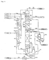
- Fig. 1 shows a flow sheet of one example of the ultra-high purity nitrogen trifluoride production unit, based on the present invention.
- the reference mark T1 represents a normal temperature adsorption column
- E1 represents a heat exchanger
- T2 represents a low temperature adsorption column
- E2 represents a reboiler
- K1 represents a medium-pressure rectification column
- E5 represents a middle condenser/reboiler
- K2 represents a low-pressure rectification column
- E6 represents a top condenser
- R represents an ultra-high purity nitrogen trifluoride product storage tank
- P1 represents a feed gas supply pipe
- P8 represents a low boiling point components discharge pipe
- P9 and P19 each represents an ultra-high purity nitrogen trifluoride product delivery pipe
- P10 represents a high boiling point components discharge pipe, respectively.
- Liquefied nitrogen is supplied as a refrigerant into the top condenser E6 by means of a
- the medium-pressure rectification column K1 comprises, in turn from below, a bottom space part 1, a lower rectifying part A, an upper rectifying part B and has the condenser side of the condenser/reboiler E5, where the reboiler E2 is installed in the bottom space part 1.
- the low-pressure rectification column K2 comprises, in turn from below, a bottom space part 2, a lower rectifying part C, an upper rectifying part D and has the condenser E6, where the reboiler side of said condenser/reboiler E5 is installed in the bottom space part 2.
- the heat exchanger E1, low temperature adsorption column T2, medium-pressure rectification column K1, low-pressure rectification column K2 and pipes and valves attached thereto are accommodated in an insulated box 41 so as to be kept at low temperatures.
- a process for producing ultra-high purity nitrogen trifluoride by use of the aforementioned unit will be described here.
- Feed nitrogen trifluoride comes out in its production, as it contains helium (He), hydrogen (H 2 ), nitrogen (N 2 ), fluorine (F 2 ), argon (Ar), oxygen (O 2 ), methane tetrafluoride (CF 4 ), dinitrogen oxide (N 2 O), carbon dioxide (CO 2 ), dinitrogen tetra-fluoride (N 2 F 4 ), hydrogen fluoride (HF), dinitrogen difluoride (N 2 F 2 ), nitrogen difluoride (NF 2 ), water (H 2 O) and etc., accompanied as impurities.
- Feed nitrogen trifluoride gas consisting of nitrogen trifluoride as a main component and containing the aforementioned impurities, pressurized under a pressure of 6 kg/cm 2 or more, is introduced into the normal temperature adsorption column T1 filled with a molecular sieve by a pipe P1 so that CO 2 and H 2 O are removed therefrom and the content of CF 4 is also decreased by its adsorption. Said feed gas is then led into the heat exchanger E1, where it is cooled down to about -70 °C through a heat exchange with low temperature nitrogen gas introduced therein as a refrigerant by a pipe P33.
- the thus-cooled feed gas is introduced into the low temperature adsorption column T2 filled with activated alumina gel through a pipe P4 so that N 2 F 2 , N 2 F 4 , N 2 O and CO 2 are removed therefrom and the content of CF4 is further decreased. Thereafter, the feed gas is introduced at about -70 °C into the reboiler E2 provided in the bottom space part 1 of the medium-pressure rectification column K1 through a pipe P5.
- the feed gas introduced at about -70 °C in the reboiler E2 is cooled down and liquefied, and at the same time heats the liquefied gas so that low boiling point gas consisting of NF 3 as a main component in the liquefied gas is evaporated and caused to rise through the rectifying part A of the medium-pressure rectification column K1.
- the feed gas which has been cooled down by the liquefied gas is liquefied in itself, taken out by a pipe P6, and expanded to a pressure of about 6 kg/cm 2 by means of an expansion valve V2 inserted in the pipe P6 so as to become a gas-liquid mixed fluid, and this gas-liquid mixed fluid is introduced into between the lower rectifying part A and upper rectifying part B.
- the gas phase which has been reboiled so as to rise in the bottom space part of the medium-pressure rectification column K1 is rectified through a direct gas-liquid contact, in the rectifying part A, with the liquid phase (a reflux liquid) of the gas-liquid mixed fluid which has been introduced in the medium-pressure rectification column K1 after expanded by the expansion valve V2, whereby components having higher boiling points than that of NF 3 , inclusive of NF 3 , flow down through the rectifying part A and components having lower boiling points than that of NF 3 , inclusive of NF 3 , rise here.
- the gas phase of the gas-liquid mixed fluid which has been introduced in the medium-pressure rectification column K1 after expanded by the expansion valve V2 rises through the rectifying part B.
- the rectification is carried out also in the rectifying part B as in the rectifying part A.
- the gas which has risen through the rectifying part B is condensed by the condenser/reboiler E5 so as to flow down here.
- the condenser/reboiler E5 In this condenser/reboiler E5, almost all of gases having higher boiling points than that of NF 3 are condensed so as to flow down.
- NF 3 and the components having lower boiling points than that of NF 3 which have not been condensed in the condenser/reboiler E5 are taken out of the condenser/reboiler E5 by a pipe P7, and expanded to a pressure of about 2 kg/cm 2 by means of an expansion valve V3 inserted in the pipe P7 so as to become a gas-liquid mixed fluid, and this gas-liquid mixed fluid is introduced into between the lower rectifying part C and upper rectifying part D of the low-pressure rectification column K2.
- the liquid phase of said gas-liquid mixed fluid introduced in the low-pressure rectification column K2 flows down through the lower rectifying part C and the gas phase thereof rises through the upper rectifying part D.
- the liquid phase thereof which flows down through said lower rectifying part C has become high purity NF 3 .
- this high purity NF 3 flows down through the lower rectifying part C, it is evaporated by the condenser/reboiler E5 and brought in a gas-liquid contact with the rising gas phase of ultra-high purity NF 3 so as to become ultra-high purity nitrogen trifluoride (NF 3 ), from which components having lower boiling points than that of NF 3 have been removed, and this ultra-high purity nitrogen trifluoride is reservoired in the bottom of the low-pressure rectification column K2.
- NF 3 ultra-high purity nitrogen trifluoride
- the gas phase which has been introduced in said low-pressure rectification column K2 and rises through the upper rectifying part D is rectified through a gas-liquid contact with a reflux liquid flowing down here, which will be mentioned below, whereby NF 3 contained in the rising gas phase is dissolved and liquefied in the reflux liquid and N 2 and He having lower boiling points than that of NF 3 , dissolved in the reflux liquid, are evaporated.
- the reflux liquid in which the concentration of NF 3 has been enhanced, is joined with the aforementioned high purity NF 3 , and caused to flow down here.
- the gas phase which has been rectified in said upper rectifying part D and rises here comprises N 2 , He and NF 3 as main components and contains further traces of H 2 , F 2 and O 2 .
- This gas phase is introduced into the condenser E6 so as to be cooled down to a temperature of about -150 °C by liquid nitrogen in the condenser E6, where a major portion of NF 3 is collected and liquefied by condensation so as to become a reflux liquid.
- This reflux liquid is caused to flow down through the upper rectifying part D and lower rectifying part C so as to become ultra-high purity nitrogen trifluoride with a purity of 99.999%, and it is reservoired in the bottom 2 of the low-pressure rectification column K2.
- Gas which has not be collected in said condenser E6 is taken out of the top of said low-pressure rectification column K2 by a pipe P8 and introduced into a harmful substances eliminating device.
- the composition of the gas taken out therefrom comprises about 54% of He, about 36% of N 2 and about 9.5% of NF 3 , and further contains traces of H 2 , F 2 and O 2 .
- Liquid reservoired in the bottom space part 1 of said medium-pressure rectification column K1 is taken out thereof by a pipe P10.
- the composition of said liquid comprises about 80% of NF 3 , about 20% of N 2 O and further contains traces of CO 2 , N 2 F 4 , H 2 O, HF, N 2 F 2 and NF 2 .
- Said liquid taken out by said pipe P10 is brought in a heat exchange with the atmospheric air in an evaporator (heat exchanger) E3 so as to become a gas-liquid mixed fluid risen in pressure, from which NF 3 is almost evaporated.
- the gas phase thereof is reduced in pressure by means of a valve V5 inserted in a pipe P11, and returned to the gas phase above a reservoired liquid in the bottom space part 1 of the medium-pressure rectification column K1.
- the liquid phase taken out by said pipe P11 is branched by a pipe P12 and introduced into the heat exchanger E4, where it is brought in a heat exchange with the atmospheric air so as to get normal temperature, and it is then introduced into the harmful substances eliminating device and discharged therefrom.
- Ultra-high purity liquid nitrogen trifluoride reservoired in the bottom space part 2 of said low-pressure rectification column K2 is taken out by a pipe P9 and stored in a product storage tank R.
- ultra-high purity nitrogen trifluoride gas can be taken out by a pipe P19.
- a plurality of said normal temperature adsorption columns T1 and low temperature adsorption columns T2 are installed and they will be switchably used.
- nitrogen gas will be heated for use in the regeneration of these normal temperature adsorption column T1 and low-temperature adsorption column T2.
- liquefied nitrogen is introduced as a refrigerant from an outside by a pipe P31.
- the liquefied nitrogen is evaporated so as to become low temperature evaporated nitrogen after its cold is utilized.
- This low temperature evaporated nitrogen is taken out by a pipe P32 and a portion thereof is branched by a pipe P33 and utilized as a cold for the heat exchanger E1.
- Nitrogen gas which has been utilized as the cold for the heat exchanger E1 is further heated and used as a regeneration gas for the normal temperature adsorption column T1 and low temperature adsorption column T2.
- the operation pressure of said low-pressure rectification column shown in Fig. 1 has been about 2 kg/cm 2 and the operation pressure of said medium-pressure rectification column about 6 kg/cm 2 , respectively.
- the operation pressure of said low-pressure rectification column may be determined to be about 1 to 7 kg/cm 2 and the operation pressure of said medium-pressure rectification column about 5 to 30 kg/cm 2 , respectively, by changing the condition of a refrigerant.
- liquefied nitrogen has been utilized as a refrigerant for introducing cold to the condenser for condensation use in the top of said low-pressure rectification column
- a simple substance of liquefied methane or a mixture of liquefied methane and liquefied ethane or liquefied propane there may be used a simple substance of liquefied methane or a mixture of liquefied methane and liquefied ethane or liquefied propane.
- the reboiler E2 condenser/reboiler E5 and condenser E6 have been installed in the rectification column, they may be installed outside of the rectification column.
- ultra-high purity nitrogen trifluoride can be easily and continuously obtained, where it is possible to carry out its mass production as compared with a production installation of the prior art and it is very useful for decreasing its production cost.
- Fig. 1 shows one example of the ultra-high purity nitrogen trifluoride production unit based on the present invention.
Landscapes
- Chemical & Material Sciences (AREA)
- Organic Chemistry (AREA)
- Inorganic Chemistry (AREA)
- Separation By Low-Temperature Treatments (AREA)
Description
- The present invention relates to a continuous low temperature rectification unit for producing nitrogen trifluoride gas with a high purity from a nitrogen trifluoride feed gas by virtue of a rectifying action caused by the gas-liquid contact of a reflux liquid and a rising gas, and particularly to a continuous low temperature rectification unit for producing ultra-high purity nitrogen trifluoride which will be used for dry etching of semi-conductors or cleaning of a CVD apparatus.
- In a unit described in the official gazette of Japanese Patent Application Laid-open No. 330,317/1995, the following procedure is carried out. Namely, raw NF3, from which N2F2 and CO2 have been previously removed and in which the purity of NF3 is 10% or more, the total mole percentage of impurities N2 and O2 is 90% or less and the amount of N2O is 500 ppm or less, is introduced into the lower part of a distillation unit kept at a temperature of a liquefied gas to be used, and liquefied by a condenser in the upper part thereof. After a predetermined amount of said raw NF3 is charged in said distillation unit, N2 and O2 whose boiling points are lower than that of NF3 are first discharged out of the upper part thereof, with carrying out temperature regulation on the lower part of a distillation column, the main body of the distillation column and the condenser in the upper part of the distillation column so that the inside of the distillation unit gets a given pressure. When such a condition is thereafter reached that the concentration of NF3 in a distillate liquid is a predetermined concentration (99.999 mol% or more), the total amount of N2 and O2 is 10 ppm or less and the amount of N2O is 1 ppm or less, a timer is actuated to open an extraction port below the condenser part so that the distillate liquid is distilled out to a receiver side.
- The unit described in the official gazette of Japanese Patent Application Laid-open No. 330,317/1995 is constructed such that three very low temperature tanks are provided to separately insulate the colds of three constituent parts such as a condenser, a distillation column and the lower part of said distillation column, and these three very low temperature tanks are separately regulated in temperature, whereby high purity nitrogen trifluoride is made in the distillation column after a given period of time has elapsed from the introduction of a feed gas, and a timer is actuated to open an extraction port below the condenser part so that a distillate liquid is distilled out into a receiver. Accordingly, this deep cold distillation unit is a batch type distillation unit and hence it is a unit not adapted for the mass production.
- Due to consideration of the aforementioned problems, the present invention is intended to provide a unit in which nitrogen trifluoride of ultra-high purity can be continuously produced by use of a simpler unit.
- An ultra-high purity nitrogen trifluoride production method, according to the present invention, is characterized by comprising: pressurizing a nitrogen trifluoride feed gas, eliminating moisture and carbon dioxide gas from said feed gas, and cooling down the same feed gas; causing the cooled feed gas to pass through adsorption columns, and introducing it into a medium-pressure rectification column by way of a reboiler in the lower part of said medium-pressure rectification column, where it is rectified in said medium-pressure rectification column; introducing the resulting gas obtained by this rectification into a middle stage of a low-pressure rectification column, where it is rectified; and taking out ultra-high purity nitrogen trifluoride obtained by virtue of this rectification from the lower part of said low-pressure rectification column.
- An ultra-high purity nitrogen trifluoride production method, according to the present invention, is further characterized by having further a step of warming, in an external heat exchanger, a liquid reservoired in the bottom of said medium-pressure rectification column so that low-boiling point components dissolved in said liquid are evaporated and returned to said medium-pressure rectification column.
- An ultra-high purity nitrogen trifluoride production method, according to the present invention, is further characterized in that the pressure of said low-pressure rectification column is an operation pressure of 1 to 7 kg/cm2.
- An ultra-high purity nitrogen trifluoride production method, according to the present invention, is further characterized in that the pressure of said medium-pressure rectification column is an operation pressure of 5 to 30 kg/cm2.
- An ultra-high purity nitrogen trifluoride production method, according to the present invention, is further characterized in that the condensation and evaporation are carried out at the same time by means of the condenser/reboiler between the upper part of said medium-pressure rectification column and the lower part of said low-pressure rectification column, and an external cold is introduced into the condenser in the upper part of said low-pressure rectification column to carry out the condensation.
- An ultra-high purity nitrogen trifluoride production method, according to the present invention is further characterized in that an external cold such as liquefied nitrogen or liquefied methane is used as a refrigerant for the condenser for condensation use of said low-pressure rectification column.
- An ultra-high purity nitrogen trifluoride production unit, according to the present invention, is characterized by comprising: a medium-pressure rectification column having a condenser/reboiler disposed in its top, a reboiler disposed in its bottom and a rectifying part provided therebetween; a low-pressure rectification column having a condenser for condensation use disposed in its top, with its bottom kept in contact with the condenser/reboiler of said medium-pressure rectification column, and having a rectifying part provided therebetween; a means for cooling down the condenser for condensation use of said low-pressure rectification column; a means for pressurizing, cooling down, and adsorptively purifying a nitrogen trifluoride feed gas; a means for introducing the pressurized feed gas obtained by said means into between the upper rectifying part and lower rectifying part in said medium-pressure rectification column; and a means for introducing the gas rectified in said medium-pressure rectification column into between the upper rectifying part and lower rectifying part in said low-pressure rectification column; where ultra-high purity nitrogen trifluoride is obtained from the lower part of said low-pressure rectification column.
- Fig. 1 shows a flow sheet of one example of the ultra-high purity nitrogen trifluoride production unit, based on the present invention. In the figure, the reference mark T1 represents a normal temperature adsorption column, E1 represents a heat exchanger, T2 represents a low temperature adsorption column, E2 represents a reboiler, K1 represents a medium-pressure rectification column, E5 represents a middle condenser/reboiler, K2 represents a low-pressure rectification column, E6 represents a top condenser, R represents an ultra-high purity nitrogen trifluoride product storage tank, P1 represents a feed gas supply pipe, P8 represents a low boiling point components discharge pipe, P9 and P19 each represents an ultra-high purity nitrogen trifluoride product delivery pipe and P10 represents a high boiling point components discharge pipe, respectively. Liquefied nitrogen is supplied as a refrigerant into the top condenser E6 by means of a pipe P31, and the thus-evaporated nitrogen gas will be taken out by a pipe P32.
- The medium-pressure rectification column K1 comprises, in turn from below, a
bottom space part 1, a lower rectifying part A, an upper rectifying part B and has the condenser side of the condenser/reboiler E5, where the reboiler E2 is installed in thebottom space part 1. The low-pressure rectification column K2 comprises, in turn from below, abottom space part 2, a lower rectifying part C, an upper rectifying part D and has the condenser E6, where the reboiler side of said condenser/reboiler E5 is installed in thebottom space part 2. In addition, the heat exchanger E1, low temperature adsorption column T2, medium-pressure rectification column K1, low-pressure rectification column K2 and pipes and valves attached thereto are accommodated in an insulatedbox 41 so as to be kept at low temperatures. Now, a process for producing ultra-high purity nitrogen trifluoride by use of the aforementioned unit will be described here. - Feed nitrogen trifluoride comes out in its production, as it contains helium (He), hydrogen (H2), nitrogen (N2), fluorine (F2), argon (Ar), oxygen (O2), methane tetrafluoride (CF4), dinitrogen oxide (N2O), carbon dioxide (CO2), dinitrogen tetra-fluoride (N2F4), hydrogen fluoride (HF), dinitrogen difluoride (N2F2), nitrogen difluoride (NF2), water (H2O) and etc., accompanied as impurities.
- Feed nitrogen trifluoride gas consisting of nitrogen trifluoride as a main component and containing the aforementioned impurities, pressurized under a pressure of 6 kg/cm2 or more, is introduced into the normal temperature adsorption column T1 filled with a molecular sieve by a pipe P1 so that CO2 and H2O are removed therefrom and the content of CF4 is also decreased by its adsorption. Said feed gas is then led into the heat exchanger E1, where it is cooled down to about -70 °C through a heat exchange with low temperature nitrogen gas introduced therein as a refrigerant by a pipe P33. The thus-cooled feed gas is introduced into the low temperature adsorption column T2 filled with activated alumina gel through a pipe P4 so that N2F2, N2F4, N2O and CO2 are removed therefrom and the content of CF4 is further decreased. Thereafter, the feed gas is introduced at about -70 °C into the reboiler E2 provided in the
bottom space part 1 of the medium-pressure rectification column K1 through a pipe P5. - Through a heat exchange with liquefied gas having a temperature of about -96 °C, reservoired in the
bottom space part 1 of the medium-pressure rectification column K1, the feed gas introduced at about -70 °C in the reboiler E2 is cooled down and liquefied, and at the same time heats the liquefied gas so that low boiling point gas consisting of NF3 as a main component in the liquefied gas is evaporated and caused to rise through the rectifying part A of the medium-pressure rectification column K1. The feed gas which has been cooled down by the liquefied gas is liquefied in itself, taken out by a pipe P6, and expanded to a pressure of about 6 kg/cm2 by means of an expansion valve V2 inserted in the pipe P6 so as to become a gas-liquid mixed fluid, and this gas-liquid mixed fluid is introduced into between the lower rectifying part A and upper rectifying part B. - The gas phase which has been reboiled so as to rise in the bottom space part of the medium-pressure rectification column K1 is rectified through a direct gas-liquid contact, in the rectifying part A, with the liquid phase (a reflux liquid) of the gas-liquid mixed fluid which has been introduced in the medium-pressure rectification column K1 after expanded by the expansion valve V2, whereby components having higher boiling points than that of NF3, inclusive of NF3, flow down through the rectifying part A and components having lower boiling points than that of NF3, inclusive of NF3, rise here. The gas phase of the gas-liquid mixed fluid which has been introduced in the medium-pressure rectification column K1 after expanded by the expansion valve V2 rises through the rectifying part B. The rectification is carried out also in the rectifying part B as in the rectifying part A. As a reflux liquid necessary in the rectifying part B, the gas which has risen through the rectifying part B is condensed by the condenser/reboiler E5 so as to flow down here. In this condenser/reboiler E5, almost all of gases having higher boiling points than that of NF3 are condensed so as to flow down.
- NF3 and the components having lower boiling points than that of NF3 which have not been condensed in the condenser/reboiler E5 are taken out of the condenser/reboiler E5 by a pipe P7, and expanded to a pressure of about 2 kg/cm2 by means of an expansion valve V3 inserted in the pipe P7 so as to become a gas-liquid mixed fluid, and this gas-liquid mixed fluid is introduced into between the lower rectifying part C and upper rectifying part D of the low-pressure rectification column K2.
- The liquid phase of said gas-liquid mixed fluid introduced in the low-pressure rectification column K2 flows down through the lower rectifying part C and the gas phase thereof rises through the upper rectifying part D. The liquid phase thereof which flows down through said lower rectifying part C has become high purity NF3. When this high purity NF3 flows down through the lower rectifying part C, it is evaporated by the condenser/reboiler E5 and brought in a gas-liquid contact with the rising gas phase of ultra-high purity NF3 so as to become ultra-high purity nitrogen trifluoride (NF3), from which components having lower boiling points than that of NF3 have been removed, and this ultra-high purity nitrogen trifluoride is reservoired in the bottom of the low-pressure rectification column K2.
- The gas phase which has been introduced in said low-pressure rectification column K2 and rises through the upper rectifying part D is rectified through a gas-liquid contact with a reflux liquid flowing down here, which will be mentioned below, whereby NF3 contained in the rising gas phase is dissolved and liquefied in the reflux liquid and N2 and He having lower boiling points than that of NF3, dissolved in the reflux liquid, are evaporated. By virtue of this rectifying action, the reflux liquid, in which the concentration of NF3 has been enhanced, is joined with the aforementioned high purity NF3, and caused to flow down here.
- The gas phase which has been rectified in said upper rectifying part D and rises here comprises N2, He and NF3 as main components and contains further traces of H2, F2 and O2. This gas phase is introduced into the condenser E6 so as to be cooled down to a temperature of about -150 °C by liquid nitrogen in the condenser E6, where a major portion of NF3 is collected and liquefied by condensation so as to become a reflux liquid. This reflux liquid is caused to flow down through the upper rectifying part D and lower rectifying part C so as to become ultra-high purity nitrogen trifluoride with a purity of 99.999%, and it is reservoired in the
bottom 2 of the low-pressure rectification column K2. - Gas which has not be collected in said condenser E6 is taken out of the top of said low-pressure rectification column K2 by a pipe P8 and introduced into a harmful substances eliminating device. The composition of the gas taken out therefrom comprises about 54% of He, about 36% of N2 and about 9.5% of NF3, and further contains traces of H2, F2 and O2.
- Liquid reservoired in the
bottom space part 1 of said medium-pressure rectification column K1 is taken out thereof by a pipe P10. At that time, the composition of said liquid comprises about 80% of NF3, about 20% of N2O and further contains traces of CO2, N2F4, H2O, HF, N2F2 and NF2. - Said liquid taken out by said pipe P10 is brought in a heat exchange with the atmospheric air in an evaporator (heat exchanger) E3 so as to become a gas-liquid mixed fluid risen in pressure, from which NF3 is almost evaporated. The gas phase thereof is reduced in pressure by means of a valve V5 inserted in a pipe P11, and returned to the gas phase above a reservoired liquid in the
bottom space part 1 of the medium-pressure rectification column K1. The liquid phase taken out by said pipe P11 is branched by a pipe P12 and introduced into the heat exchanger E4, where it is brought in a heat exchange with the atmospheric air so as to get normal temperature, and it is then introduced into the harmful substances eliminating device and discharged therefrom. - Ultra-high purity liquid nitrogen trifluoride reservoired in the
bottom space part 2 of said low-pressure rectification column K2 is taken out by a pipe P9 and stored in a product storage tank R. In addition, ultra-high purity nitrogen trifluoride gas can be taken out by a pipe P19. - In a practical unit, although not illustrated in Fig. 1, a plurality of said normal temperature adsorption columns T1 and low temperature adsorption columns T2 are installed and they will be switchably used. In addition, nitrogen gas will be heated for use in the regeneration of these normal temperature adsorption column T1 and low-temperature adsorption column T2.
- Into the condenser E6 of the low-pressure rectification column K2, liquefied nitrogen is introduced as a refrigerant from an outside by a pipe P31. The liquefied nitrogen is evaporated so as to become low temperature evaporated nitrogen after its cold is utilized. This low temperature evaporated nitrogen is taken out by a pipe P32 and a portion thereof is branched by a pipe P33 and utilized as a cold for the heat exchanger E1. Nitrogen gas which has been utilized as the cold for the heat exchanger E1 is further heated and used as a regeneration gas for the normal temperature adsorption column T1 and low temperature adsorption column T2.
- In the embodiment of the aforementioned invention, the operation pressure of said low-pressure rectification column shown in Fig. 1 has been about 2 kg/cm2 and the operation pressure of said medium-pressure rectification column about 6 kg/cm2, respectively. However, the operation pressure of said low-pressure rectification column may be determined to be about 1 to 7 kg/cm2 and the operation pressure of said medium-pressure rectification column about 5 to 30 kg/cm2, respectively, by changing the condition of a refrigerant. Although liquefied nitrogen has been utilized as a refrigerant for introducing cold to the condenser for condensation use in the top of said low-pressure rectification column, there may be used a simple substance of liquefied methane or a mixture of liquefied methane and liquefied ethane or liquefied propane. Furthermore, although the reboiler E2, condenser/reboiler E5 and condenser E6 have been installed in the rectification column, they may be installed outside of the rectification column.
- According to the ultra-high purity nitrogen trifluoride production method and the unit therefor having the aforementioned construction, based on the present invention, ultra-high purity nitrogen trifluoride can be easily and continuously obtained, where it is possible to carry out its mass production as compared with a production installation of the prior art and it is very useful for decreasing its production cost.
- Fig. 1 shows one example of the ultra-high purity nitrogen trifluoride production unit based on the present invention.
- T1 -- normal temperature adsorption column, T2 - low temperature adsorption column, K1 -- medium-pressure rectification column, k2 -- low-pressure rectification column, E2 -- reboiler, 1, 2 -- bottom space parts, A, B, C, D -- rectifying parts, E1, E3, E4 -- heat exchangers, E5 -- condenser/reboiler, E6 -- condenser, R -- product storage tank, V1, V2, V3 -- expansion valves, P - -pipe, and 41 -- insulated box.
Claims (7)
- An ultra-high purity nitrogen trifluoride production method, which comprises:pressurizing a nitrogen trifluoride feed gas, eliminating moisture and carbon dioxide gas from said feed gas, and cooling down the same feed gas;causing the cooled feed gas to pass through adsorption columns (T1, T2), and introducing it into a medium-pressure rectification column (K1) by way of a reboiler (E2) in the lower part of said medium-pressure rectification column, where it is rectified in said medium-pressure rectification column;introducing the resulting gas obtained by this rectification into a middle stage of a low-pressure rectification column (K2), where it is rectified; andtaking out ultra-high purity nitrogen trifluoride obtained by virtue of this rectification from the lower part of said low-pressure rectification column.
- An ultra-high purity nitrogen trifluoride production method, according to claim 1, which further comprises:warming, in an external heat exchanger, a liquid reservoired in the bottom of said medium-pressure rectification column (K1) so that low-boiling point components dissolved in said liquid are evaporated and returned to said medium-pressure rectification column.
- An ultra-high purity nitrogen trifluoride production method, according to claim 1 or 2, in which the pressure of said low-pressure rectification column (K2) is an operation pressure of 1 to 7 kg/cm2.
- An ultra-high purity nitrogen trifluoride production method, according to any of claims 1 to 3, in which the pressure of said medium-pressure rectification column (K1) is an operation pressure of 5 to 30 kg/cm2.
- An ultra-high purity nitrogen trifluoride production method, according to any of claims 1 to 3, in which the condensation and evaporation are carried out at the same time by means of a condenser/reboiler (E5) between the upper part of said medium-pressure rectification column and the lower part of said low-pressure rectification column, and an external cold is introduced into a condenser in the upper part of said low-pressure rectification column to carry out the condensation.
- An ultra-high purity nitrogen trifluoride production method, according to any of claims 1 to 4, in which an external cold such as liquefied nitrogen or liquefied methane is used as a refrigerant for a condenser for condensation use of said low-pressure rectification column.
- An ultra-high purity nitrogen trifluoride production unit, which comprises:where ultra-high purity nitrogen trifluoride is obtained from the lower part of said low-pressure rectification column.a medium-pressure rectification column (K1) having a condenser/reboiler (E5) disposed in its top, a reboiler (E2) disposed in its bottom and a rectifying part provided therebetween;a low-pressure rectification column (K2) having a condenser (E6) for condensation use disposed in its top, with its bottom kept in contact with the condenser/reboiler (E5) of said medium-pressure rectification column, and having a rectifying part provided therebetween;means for cooling down the condenser for condensation use of said low-pressure rectification column;means for pressurizing, cooling down, and adsorptively purifying a nitrogen trifluoride feed gas;means (P6) for introducing the pressurized feed gas obtained by said aforementioned means into between the upper rectifying part and lower rectifying part in said medium-pressure rectification column; andmeans (P7) for introducing the gas rectified in said medium-pressure rectification column into between the upper rectifying part and lower rectifying part in said low-pressure rectification column;
Applications Claiming Priority (3)
| Application Number | Priority Date | Filing Date | Title |
|---|---|---|---|
| JP11889896A JP3532345B2 (en) | 1996-05-14 | 1996-05-14 | Method and apparatus for producing ultra-high purity nitrogen trifluoride |
| JP118898/96 | 1996-05-14 | ||
| JP11889896 | 1996-05-14 |
Publications (2)
| Publication Number | Publication Date |
|---|---|
| EP0807600A1 EP0807600A1 (en) | 1997-11-19 |
| EP0807600B1 true EP0807600B1 (en) | 2000-01-12 |
Family
ID=14747905
Family Applications (1)
| Application Number | Title | Priority Date | Filing Date |
|---|---|---|---|
| EP97401058A Expired - Lifetime EP0807600B1 (en) | 1996-05-14 | 1997-05-13 | Ultra-high purity nitrogen trifluoride production method, and unit therefor |
Country Status (4)
| Country | Link |
|---|---|
| US (1) | US5832746A (en) |
| EP (1) | EP0807600B1 (en) |
| JP (1) | JP3532345B2 (en) |
| DE (1) | DE69701106T2 (en) |
Cited By (1)
| Publication number | Priority date | Publication date | Assignee | Title |
|---|---|---|---|---|
| SG125089A1 (en) * | 2002-08-23 | 2006-09-29 | Boc Group Inc | Method and apparatus for producing a purified liquid |
Families Citing this family (15)
| Publication number | Priority date | Publication date | Assignee | Title |
|---|---|---|---|---|
| US5910294A (en) * | 1997-11-17 | 1999-06-08 | Air Products And Chemicals, Inc. | Abatement of NF3 with metal oxalates |
| JP3979714B2 (en) * | 1997-12-22 | 2007-09-19 | 日本エア・リキード株式会社 | Fluorine compound separation and purification method and equipment |
| US6122931A (en) * | 1998-04-07 | 2000-09-26 | American Air Liquide Inc. | System and method for delivery of a vapor phase product to a point of use |
| US6276168B1 (en) * | 2000-05-08 | 2001-08-21 | Air Products And Chemicals, Inc. | Purification of nitrogen trifluoride by continuous cryogenic distillation |
| US6457327B1 (en) * | 2000-05-08 | 2002-10-01 | Air Products And Chemicals, Inc. | Process for concentrating fluorine compounds |
| US20040191155A1 (en) * | 2003-03-25 | 2004-09-30 | Mahler Barry Asher | Thermal process for reducing the concentration of dinitrogen difluoride and dinitrogen tetrafluoride in nitrogen trifluoride |
| US20050016829A1 (en) * | 2003-04-14 | 2005-01-27 | Miller Ralph Newton | Distillation process for reducing the concentration of dinitrogen difluoride and dinitrogen tetrafluoride in nitrogen trifluoride |
| US7074378B2 (en) * | 2004-01-23 | 2006-07-11 | Air Products And Chemicals, Inc. | Process for the purification of NF3 |
| US20070204631A1 (en) * | 2006-03-03 | 2007-09-06 | American Air Liquide, Inc. | Liquefied Chemical Gas Delivery System |
| US20080044572A1 (en) * | 2006-08-15 | 2008-02-21 | Loeffler Stephen D | Right-sized vacuum precursor (rsvp) distillation system |
| CN102774845A (en) * | 2012-07-06 | 2012-11-14 | 天津大学 | Device and method for producing boron trifluoride-11 electronic specific gas |
| CN103759501A (en) * | 2014-01-16 | 2014-04-30 | 上海交通大学 | Low-temperature rectification device for production of ultra-pure xenon |
| CN111056540B (en) * | 2019-12-25 | 2023-09-15 | 中船(邯郸)派瑞特种气体股份有限公司 | Electrolytic NF 3 Continuous prepurification device and continuous prepurification method |
| CN112390230A (en) * | 2020-11-20 | 2021-02-23 | 苏州金宏气体股份有限公司 | Purification method and purification system of chlorine trifluoride |
| CN114538391B (en) * | 2022-03-01 | 2023-11-03 | 中船(邯郸)派瑞特种气体股份有限公司 | From NF 3 Recovery of high purity N from exhaust gas 2 O device and recovery method thereof |
Family Cites Families (8)
| Publication number | Priority date | Publication date | Assignee | Title |
|---|---|---|---|---|
| US2960835A (en) * | 1958-06-10 | 1960-11-22 | Air Prod Inc | Separation of gaseous mixtures |
| JPS4842620B1 (en) * | 1968-01-12 | 1973-12-13 | ||
| JPH0755807B2 (en) * | 1987-11-04 | 1995-06-14 | 三井東圧化学株式会社 | Method for producing nitrogen trifluoride |
| US5150577A (en) * | 1991-06-11 | 1992-09-29 | Mitchell Mark D | System and method for recovering and purifying a halocarbon composition |
| US5426944A (en) * | 1993-08-31 | 1995-06-27 | American Air Liquide, Inc. | Chemical purification for semiconductor processing by partial condensation |
| JPH07330317A (en) * | 1994-06-02 | 1995-12-19 | Nissan Chem Ind Ltd | Low-temperature distillation apparatus for nitrogen trifluoride gas |
| US5502969A (en) * | 1995-02-16 | 1996-04-02 | Praxair Technology, Inc. | Cryogenic rectification system for fluorine compound recovery |
| US5626023A (en) * | 1995-02-16 | 1997-05-06 | Praxair Technology, Inc. | Cryogenic rectification system for fluorine compound recovery using additive liquid |
-
1996
- 1996-05-14 JP JP11889896A patent/JP3532345B2/en not_active Expired - Fee Related
-
1997
- 1997-05-13 DE DE69701106T patent/DE69701106T2/en not_active Expired - Fee Related
- 1997-05-13 EP EP97401058A patent/EP0807600B1/en not_active Expired - Lifetime
- 1997-05-14 US US08/856,005 patent/US5832746A/en not_active Expired - Fee Related
Cited By (1)
| Publication number | Priority date | Publication date | Assignee | Title |
|---|---|---|---|---|
| SG125089A1 (en) * | 2002-08-23 | 2006-09-29 | Boc Group Inc | Method and apparatus for producing a purified liquid |
Also Published As
| Publication number | Publication date |
|---|---|
| DE69701106T2 (en) | 2000-08-24 |
| US5832746A (en) | 1998-11-10 |
| DE69701106D1 (en) | 2000-02-17 |
| JPH09303955A (en) | 1997-11-28 |
| EP0807600A1 (en) | 1997-11-19 |
| JP3532345B2 (en) | 2004-05-31 |
Similar Documents
| Publication | Publication Date | Title |
|---|---|---|
| EP0807600B1 (en) | Ultra-high purity nitrogen trifluoride production method, and unit therefor | |
| KR900007207B1 (en) | Ultra high purity oxygen production method | |
| CA2893197C (en) | Argon production method and apparatus | |
| US5159816A (en) | Method of purifying argon through cryogenic adsorption | |
| EP0194795B1 (en) | Purification of carbon dioxide for use in brewing | |
| US5685169A (en) | Method and apparatus for preparing high purity hydrogen bromide | |
| JPH0735470A (en) | Method and device for manufacturing superhigh purity dinitrogen monoxide | |
| US20060000702A1 (en) | Method for separating a krypton-xenon concentrate and a device for carrying out said method | |
| EP0727629A2 (en) | Cryogenic rectification system for fluorine compound recovery | |
| WO1986000693A1 (en) | Apparatus for producing high-frequency nitrogen gas | |
| KR20010049629A (en) | Pfc recovery using condensation | |
| RU2069293C1 (en) | Cryogenic method of producing nitrogen from air | |
| EP0301514B1 (en) | Process and apparatus to produce ultra high purity oxygen from a liquid feed | |
| KR100328608B1 (en) | Cryogenic rectification regenerator system | |
| US5771713A (en) | Cryogenic rectification system for recovery of fluorine compounds | |
| JP2636949B2 (en) | Improved nitrogen generator | |
| JPWO1997001068A1 (en) | Argon separation method and apparatus | |
| US6276167B1 (en) | Refrigeration production | |
| JP3472631B2 (en) | Air separation equipment | |
| JPH09217982A (en) | Air liquefaction separation device and air liquefaction separation method | |
| US20020095951A1 (en) | Method and apparatuses for the production of synthetic air products and related gases | |
| KR960003274B1 (en) | Low Temperature Air Separation System with Hybrid Argon Column | |
| US3258929A (en) | Liquefaction and separation of air components | |
| RU2406047C1 (en) | Method of producing krypton-xenon mixture and special purity oxygen and device for realising said method | |
| JPS6086015A (en) | Purification of liquefied carbonic acid |
Legal Events
| Date | Code | Title | Description |
|---|---|---|---|
| PUAI | Public reference made under article 153(3) epc to a published international application that has entered the european phase |
Free format text: ORIGINAL CODE: 0009012 |
|
| 17P | Request for examination filed |
Effective date: 19970517 |
|
| AK | Designated contracting states |
Kind code of ref document: A1 Designated state(s): DE FR GB IT NL |
|
| RAP1 | Party data changed (applicant data changed or rights of an application transferred) |
Owner name: AIR LIQUIDE JAPAN, LTD. |
|
| GRAG | Despatch of communication of intention to grant |
Free format text: ORIGINAL CODE: EPIDOS AGRA |
|
| 17Q | First examination report despatched |
Effective date: 19990311 |
|
| GRAG | Despatch of communication of intention to grant |
Free format text: ORIGINAL CODE: EPIDOS AGRA |
|
| GRAG | Despatch of communication of intention to grant |
Free format text: ORIGINAL CODE: EPIDOS AGRA |
|
| GRAH | Despatch of communication of intention to grant a patent |
Free format text: ORIGINAL CODE: EPIDOS IGRA |
|
| GRAH | Despatch of communication of intention to grant a patent |
Free format text: ORIGINAL CODE: EPIDOS IGRA |
|
| GRAA | (expected) grant |
Free format text: ORIGINAL CODE: 0009210 |
|
| AK | Designated contracting states |
Kind code of ref document: B1 Designated state(s): DE FR GB IT NL |
|
| REF | Corresponds to: |
Ref document number: 69701106 Country of ref document: DE Date of ref document: 20000217 |
|
| ITF | It: translation for a ep patent filed | ||
| EN | Fr: translation not filed | ||
| REG | Reference to a national code |
Ref country code: FR Ref legal event code: RN |
|
| REG | Reference to a national code |
Ref country code: FR Ref legal event code: FC |
|
| ET | Fr: translation filed | ||
| PLBE | No opposition filed within time limit |
Free format text: ORIGINAL CODE: 0009261 |
|
| STAA | Information on the status of an ep patent application or granted ep patent |
Free format text: STATUS: NO OPPOSITION FILED WITHIN TIME LIMIT |
|
| 26N | No opposition filed | ||
| REG | Reference to a national code |
Ref country code: GB Ref legal event code: IF02 |
|
| PGFP | Annual fee paid to national office [announced via postgrant information from national office to epo] |
Ref country code: NL Payment date: 20020415 Year of fee payment: 6 |
|
| PGFP | Annual fee paid to national office [announced via postgrant information from national office to epo] |
Ref country code: GB Payment date: 20020417 Year of fee payment: 6 |
|
| PGFP | Annual fee paid to national office [announced via postgrant information from national office to epo] |
Ref country code: DE Payment date: 20020423 Year of fee payment: 6 |
|
| PGFP | Annual fee paid to national office [announced via postgrant information from national office to epo] |
Ref country code: FR Payment date: 20030411 Year of fee payment: 7 |
|
| PG25 | Lapsed in a contracting state [announced via postgrant information from national office to epo] |
Ref country code: GB Free format text: LAPSE BECAUSE OF NON-PAYMENT OF DUE FEES Effective date: 20030513 |
|
| PG25 | Lapsed in a contracting state [announced via postgrant information from national office to epo] |
Ref country code: NL Free format text: LAPSE BECAUSE OF NON-PAYMENT OF DUE FEES Effective date: 20031201 |
|
| PG25 | Lapsed in a contracting state [announced via postgrant information from national office to epo] |
Ref country code: DE Free format text: LAPSE BECAUSE OF NON-PAYMENT OF DUE FEES Effective date: 20031202 |
|
| GBPC | Gb: european patent ceased through non-payment of renewal fee |
Effective date: 20030513 |
|
| NLV4 | Nl: lapsed or anulled due to non-payment of the annual fee |
Effective date: 20031201 |
|
| PG25 | Lapsed in a contracting state [announced via postgrant information from national office to epo] |
Ref country code: FR Free format text: LAPSE BECAUSE OF NON-PAYMENT OF DUE FEES Effective date: 20050131 |
|
| REG | Reference to a national code |
Ref country code: FR Ref legal event code: ST |
|
| PG25 | Lapsed in a contracting state [announced via postgrant information from national office to epo] |
Ref country code: IT Free format text: LAPSE BECAUSE OF NON-PAYMENT OF DUE FEES Effective date: 20050513 |