EP0807593A2 - Sheet transfer system - Google Patents
Sheet transfer system Download PDFInfo
- Publication number
- EP0807593A2 EP0807593A2 EP97107729A EP97107729A EP0807593A2 EP 0807593 A2 EP0807593 A2 EP 0807593A2 EP 97107729 A EP97107729 A EP 97107729A EP 97107729 A EP97107729 A EP 97107729A EP 0807593 A2 EP0807593 A2 EP 0807593A2
- Authority
- EP
- European Patent Office
- Prior art keywords
- sheet
- sheets
- bent portion
- air
- conveyance
- Prior art date
- Legal status (The legal status is an assumption and is not a legal conclusion. Google has not performed a legal analysis and makes no representation as to the accuracy of the status listed.)
- Granted
Links
Images

Classifications
-
- B—PERFORMING OPERATIONS; TRANSPORTING
- B65—CONVEYING; PACKING; STORING; HANDLING THIN OR FILAMENTARY MATERIAL
- B65H—HANDLING THIN OR FILAMENTARY MATERIAL, e.g. SHEETS, WEBS, CABLES
- B65H31/00—Pile receivers
- B65H31/24—Pile receivers multiple or compartmented, e.d. for alternate, programmed, or selective filling
-
- B—PERFORMING OPERATIONS; TRANSPORTING
- B65—CONVEYING; PACKING; STORING; HANDLING THIN OR FILAMENTARY MATERIAL
- B65H—HANDLING THIN OR FILAMENTARY MATERIAL, e.g. SHEETS, WEBS, CABLES
- B65H29/00—Delivering or advancing articles from machines; Advancing articles to or into piles
- B65H29/24—Delivering or advancing articles from machines; Advancing articles to or into piles by air blast or suction apparatus
- B65H29/241—Suction devices
- B65H29/242—Suction bands or belts
-
- B—PERFORMING OPERATIONS; TRANSPORTING
- B65—CONVEYING; PACKING; STORING; HANDLING THIN OR FILAMENTARY MATERIAL
- B65H—HANDLING THIN OR FILAMENTARY MATERIAL, e.g. SHEETS, WEBS, CABLES
- B65H2406/00—Means using fluid
-
- B—PERFORMING OPERATIONS; TRANSPORTING
- B65—CONVEYING; PACKING; STORING; HANDLING THIN OR FILAMENTARY MATERIAL
- B65H—HANDLING THIN OR FILAMENTARY MATERIAL, e.g. SHEETS, WEBS, CABLES
- B65H2406/00—Means using fluid
- B65H2406/10—Means using fluid made only for exhausting gaseous medium
- B65H2406/12—Means using fluid made only for exhausting gaseous medium producing gas blast
- B65H2406/121—Fan
-
- B—PERFORMING OPERATIONS; TRANSPORTING
- B65—CONVEYING; PACKING; STORING; HANDLING THIN OR FILAMENTARY MATERIAL
- B65H—HANDLING THIN OR FILAMENTARY MATERIAL, e.g. SHEETS, WEBS, CABLES
- B65H2406/00—Means using fluid
- B65H2406/30—Suction means
-
- B—PERFORMING OPERATIONS; TRANSPORTING
- B65—CONVEYING; PACKING; STORING; HANDLING THIN OR FILAMENTARY MATERIAL
- B65H—HANDLING THIN OR FILAMENTARY MATERIAL, e.g. SHEETS, WEBS, CABLES
- B65H2801/00—Application field
- B65H2801/03—Image reproduction devices
- B65H2801/06—Office-type machines, e.g. photocopiers
Definitions
- This invention relates to a sheet transfer system which conveys sheets attracting the back side thereof under vacuum without contacting the front side of the sheets for use, for instance, in a sheet sorter which is provided with a plurality of bins each of which receives a plurality of sheets discharged from an image recording apparatus such as a printer, a copier or the like and forms thereon a stack of sheets.
- sheets are conveyed held between a pair of conveyor rollers.
- conveyor rollers cannot be used since the rollers are contaminated with ink and the images on the sheets are deteriorated through contact of the rollers with the printed sides of the sheets.
- sheets wet with ink are conveyed by a system which conveys sheets attracting the back side thereof under vacuum without contacting the front side of the sheets.
- the primary object of the present invention is to provide a sheet transfer system which conveys sheets holding their back sides without contacting their front sides and can surely convey the sheets even if the conveyance passage is bent.
- the sheet transfer system of the present invention is characterized in that an air blower is provided to blow an air flow against the surface of the conveyor at the bent portion of the conveyance passage so that the sheets are bent along the surface of the conveyor.
- the sheets are conveyed by a conveyor belt which attracts the back sides of the sheets under vacuum and the conveyor belt is bent along a pulley.
- an exhaust fan be provided to exhaust air in a direction perpendicular to the direction of conveyance of the sheets inside of the bent portion of the conveyance passage.
- the exhaust fan is provided inside of a pulley along which the conveyance passage is bent and which is rotated about a rotational axis perpendicular to the direction of conveyance of the sheets in view of simplifying the structure.
- a plurality of blowers be arranged in the direction of conveyance around the bent portion with at least one of the blowers positioned so as to blow an air flow against the top portion of bent portion and the air flow from said at least one of the blowers be stronger than those from the other blowers.
- This arrangement is advantageous in that the sheet can be surely bent along the bent portion of the conveyance passage by blowing a strong air flow against a place where the sheet is the toughest.
- the strength of the air flow blown from the air blower is adjustable according to the kind of sheets to be conveyed.
- the strength of the air flow blown from the air blower is increased as the thickness of the sheets to be conveyed increases.
- the sheets are bent along the bent portion of the conveyance passage by the air blower, whereby the sheets can be successfully conveyed along the bent portion of the conveyance passage without contacting the front side of the sheets with no fear that the sheets project outside the conveyance passage.
- the sheets can be bent along the bent portion of the conveyance passage by an air flow whose strength is optimal to bend the sheets according to the resiliency of the sheets which varies according to the material, thickness and the like of the sheets, whereby the sheets can be more surely conveyed along the bent portion of the conveyance passage without adverse affect of an excessively strong air flow.
- a sheet sorter S comprises a plurality of (e.g., fifty) bins (sort trays) 4 which are disposed in fixed positions in a frame 3 at predetermined intervals in the vertical direction and receive a plurality of recorded sheets 2 discharged from an image recording apparatus 1 such as a printer to form a stack of the sheets 2 on each bin 4, a sheet transfer system 5 which transfers the sheets 2 discharged from the image recording apparatus 1 toward the bins 4, an indexer 6 which is movable up and down along the array of the sheet inlet ends of the bins 4 and distributes the sheets 2, transferred by the sheet transfer system 5, to the respective bins 4 by a curved guide surface which deflects the sheets 2, and a stapler 7 which is movable up and down along the array of the sheet inlet ends of the bins 4 and in a horizontal direction and staples the stack of sheets on each bin 4.
- an image recording apparatus 1 such as a printer to form a stack of the sheets 2 on each bin 4
- a sheet transfer system 5 which transfers the sheets 2 discharged from
- the image recording apparatus 1 is a printer, especially a stencil printer
- a number of sheets can be printed in a short time and recorded sheets 2 carrying thereon wet ink are discharged at a high rate. Accordingly no conveyor roller is used in the sheet transfer system 5 and the sheet transfer system 5 conveys the sheets 2 attracting the back sides thereof under vacuum without contacting the front sides of the sheets 2.
- the sheet transfer system 5 comprises a first conveyor portion 5A which extends obliquely upward to an upper portion of the sheet sorter S and a second conveyor portion 5B which vertically extends downward along the path of travel of the indexer 6.
- the upper portions of the first and second conveyor portions 5A and 5B are at an acute angle relative to each other to form a bent portion 5C. That is, the sheets 2 discharged from the image recording apparatus 1 is conveyed obliquely upward to the bent portion 5C by the first conveyor portion 5A and delivered to the second conveyor portion 5B by way of the bent portion 5C.
- the first conveyor portion 5A basically comprises a pair of perforated endless conveyor belts 9 each passed around a pair of pulleys 16 and suction blowers 8 disposed inside the conveyor belts 9, and conveys the sheets 2 with the back side of the sheets 2 attracted against the belts 9 under vacuum applied by the suction blowers 8.
- the second conveyor portion 5B basically comprises a perforated endless conveyor belt 10 passed around a pair of pulleys 17 and suction blowers 8 disposed inside the conveyor belt 10, and conveys the sheets 2 with the back side of the sheets 2 attracted against the belt 10 under vacuum applied by the suction blowers 8.
- an air blower 11 blows an air flow against the surface of the conveyor belt 10 at the bent portion 5C, thereby pressing the sheets 2 against the surface of the conveyor belt 10.
- the sheet sorter S is arranged so that a plurality of slaves S' having the same structure as the main sheet sorter S can be connected to the sheet sorter S as shown in Figure 1 in order to increase the total number of the bins 4.
- the slaves S' are connected to the main sheet sorter S on the side remote from the image recording apparatus 1.
- a sheet conveyor 12 is demountably mounted on an upper portion of the main sheet sorter S and the sheets 2 in the main sheet sorter S are transferred to the slaves S' by the sheet conveyor 12 when the slaves S' are connected to the main sheet sorter S.
- the image recording apparatus 1 is provided with a sheet tray 13 on which the discharged sheets 2 are stacked when sorting of the sheets 2 is not necessary. Further a control panel 14 and an exterior electric stapler 15 are mounted on the outer surface of the sheet sorter S.
- a pair of side lineup rods 21a and 21b which push the sheet 2 in the direction of width of the sheet 2 and bring the side edge of the sheet 2 into abutment against the side edge reference surface
- a trailing edge lineup rod 26 which pushes the leading edge of the sheet 2 to move the sheet 2 toward the sheet inlet end of the bin 4 so that the trailing edge of the sheet 2 is brought into abutment against a trailing edge reference surface defined by a metal web 30 which is fed out from a roll to close the sheet inlet ends of the bins 4 above the indexer 6 in response to a downward movement of the indexer 6 and is taken up around the roll in response to an upward movement of the indexer 6.
- a sheet stack ejector 25 is mounted on the rod 26 to be movable up and down along the rod 26. After completion of distribution of the sheets 2 to all the bins 4 by the indexer 6, the sheet stack ejector 25 pushes the sheet stacks 20 on the respective bins 4 to eject them into the path of travel of the indexer 6 for stapling operation.
- the first conveyor portion 5A comprises upper and lower sections and the upper and lower sections are substantially the same in structure. Accordingly only the upper section will be described here.
- the upper section of the first conveyor portion 5A comprises three perforated conveyor belts 9 each passed around upper and lower small diameter pulleys 16.
- the three upper small diameter pulleys 16 are arranged in a row in a direction perpendicular to the sheet conveyance direction at the upper end of the first conveyor portion 5A and the three lower small diameter pulleys 16 are arranged in a row in a direction perpendicular to the sheet conveyance direction at the lower end of the first conveyor portion 5A.
- a box-like duct 18 is disposed on the back side of the conveyor belts 9. The inside of the duct 18 is kept under vacuum by the suction blowers 8 ( Figure 2) and an opening (not shown) is formed in the surface of the duct 18 facing the upper run of the conveyor belts 9 so that the sheet 2 on the conveyor belts 9 is attracted against the front side of the belts 9 under vacuum.
- the second conveyor portion 5B comprises three perforated conveyor belts 10 each passed around upper and lower larger diameter pulleys 17.
- the three upper larger diameter pulleys 17 are arranged in a row in a direction perpendicular to the sheet conveyance direction at the upper end of the second conveyor portion 5B or the bent portion 5C and the three lower larger diameter pulleys 17 are arranged in a row in a direction perpendicular to the sheet conveyance direction at the lower end of the second conveyor portion 5B. Only a part of perforations in the conveyor belts 10 are shown in Figure 4 and only the upper larger diameter pulleys 17 are shown in Figure 4.
- a duct similar to the duct 18 of the first conveyor portion 5A is disposed on the back side of the conveyor belts 10 so that the sheet 2 on the conveyor belts 10 is attracted against the front side of the belts 10 under vacuum.
- a pair of guide members extend along the conveyor belts 10 among them at the bent portion 5C.
- First to third air blower assemblies are arranged in the direction of conveyance around the bent portion 5C and blow air flows toward the surfaces of the conveyor belts 10 so that the sheet 2 on the belts 10 is bent along the bent portion 5C by the pressure of the air flows and is conveyed to the indexer 6 by the second conveyor portion 5B through the bent portion 5C as the conveyor belts 10 run.
- the first air blower assembly is disposed on the first conveyor portion side of the top of the bent portion 5C and comprises a pair of axial flow air blowers 11a arranged in a direction perpendicular to the conveyance direction.
- the air flows from the air blowers 11a are directed slightly downstream to give the leading end portion of the sheet 2 approaching the bent portion 5C occasion to bend along the bent portion 5C.
- the second air blower assembly is disposed opposed to the top of the bent portion 5C and comprises three axial flow air blowers 11b arranged in a direction perpendicular to the conveyance direction.
- the air flows from the air blowers 11b are directed slightly downstream to wind the sheet 2 around the bent portion 5C.
- the air flow rate of the air flows from the second air blower assembly opposed to the top of the bent portion 5C is larger than those from the other air blower assemblies.
- the third air blower assembly is disposed on the second conveyor portion side of the top of the bent portion 5C and comprises a pair of centrifugal air blowers 11c arranged in a direction perpendicular to the conveyance direction.
- the air blowers 11c are arranged to blow air flows in their circumferential directions due to spatial limitation.
- the air flows from the air blowers 11c are directed slightly downstream to keep flat the leading end portion of the sheet 2 along the surfaces of the conveyor belts 10 at the boundary between the bent portion 5C and the flat portion.
- Exhaust fans 19 are provided inside of the bent portion 5C to exhaust air in a direction perpendicular to the direction of conveyance of the sheets 2.
- the exhaust fans 19 are formed by propeller-like arms of the larger diameter pulleys 17 which are rotated about a rotational axis perpendicular to the direction of conveyance of the sheets 2.
- the exhaust fans 19 discharge excessive air flow outside the sheet sorter S through a side wall of the sorter S near the back side thereof, thereby preventing a turbulent flow inside the bent portion 5C.
- the strength of the air flows blown from the air blower assemblies opposed to the bent portion 5C is adjustable according to the kind of sheets 2 to be conveyed. More specifically, the kind of sheets 2 is determined on the basis of information on the resiliency of the sheets 2 and, for example, the strength of the air flows is increased as the thickness of the sheets 2 increases on the basis of sheet thickness information.
- the image recording apparatus 1 there is generally provided a manual or automatic adjustment mechanism for adjusting the printing pressure and the like according to the thickness of the sheets. Accordingly it is preferred that the flow rate of the air flows be adjusted on the basis of the sheet thickness information obtained from the adjustment mechanism.
- the sheet thickness information may be set through an input means such as a control panel provided on the image recording apparatus or the sheet sorter.
- the sheets can be successfully conveyed along the bent portion 5C.
- An outer guide member 31 is disposed outside the top of the bent portion 5C in order to prevent the sheets 2 from scattering, for instance, when the air blower assemblies are not operating. Further a flap 32 is mounted for rotation about a pivot pin 32a near the bent portion 5C. The flap 32 is rotated in the counterclockwise direction in Figure 3 so that its one arm is brought into contact with the upper surface of the conveyor belt 10 when the sheets 2 are to be delivered to the sheet conveyor 12 which transfers the sheets 2 to the slaves S'.
- the flow rate of the air blower assemblies is adjusted according to the thickness of the sheets
- the flow rate of the air blower assemblies may be adjusted according to the density of the sheets so that the flow rate is increased as the density of the sheets increases.
- the control means for adjusting the flow rate may be provided either on the image recording apparatus or on the sheet sorter.
Landscapes
- Engineering & Computer Science (AREA)
- Mechanical Engineering (AREA)
- Delivering By Means Of Belts And Rollers (AREA)
- Collation Of Sheets And Webs (AREA)
- Separation, Sorting, Adjustment, Or Bending Of Sheets To Be Conveyed (AREA)
Abstract
Description
- This invention relates to a sheet transfer system which conveys sheets attracting the back side thereof under vacuum without contacting the front side of the sheets for use, for instance, in a sheet sorter which is provided with a plurality of bins each of which receives a plurality of sheets discharged from an image recording apparatus such as a printer, a copier or the like and forms thereon a stack of sheets.
- Generally sheets are conveyed held between a pair of conveyor rollers. However in the case of sheets carrying thereon wet ink like printed sheets just discharged from a printer such as a stencil printer, such conveyor rollers cannot be used since the rollers are contaminated with ink and the images on the sheets are deteriorated through contact of the rollers with the printed sides of the sheets. Accordingly sheets wet with ink are conveyed by a system which conveys sheets attracting the back side thereof under vacuum without contacting the front side of the sheets.
- In order to make compact an apparatus such as a sheet sorter, it is necessary to bend the conveyance passage of the sheets, for instance, at an acute angle.
- In the case of a transfer system in which the sheets are conveyed with the back side thereof attracted against a conveyor belt under vacuum, it is difficult to attract the sheets so that the sheets are sufficiently bent along the bent conveyance passage unless a substantially large suction apparatus is used since the sheets are spaced from each other and the vacuum system is not closed. Especially when the sheets are large in thickness or the conveying speed is high, the leading end portion of the sheet will project outside the conveyance passage away from the conveyor belt when passing the bent portion of the conveyance passage, which can result in jam of the transfer system.
- In view of the foregoing observations and description, the primary object of the present invention is to provide a sheet transfer system which conveys sheets holding their back sides without contacting their front sides and can surely convey the sheets even if the conveyance passage is bent.
- The sheet transfer system of the present invention is characterized in that an air blower is provided to blow an air flow against the surface of the conveyor at the bent portion of the conveyance passage so that the sheets are bent along the surface of the conveyor.
- Specifically the sheets are conveyed by a conveyor belt which attracts the back sides of the sheets under vacuum and the conveyor belt is bent along a pulley.
- It is preferred that an exhaust fan be provided to exhaust air in a direction perpendicular to the direction of conveyance of the sheets inside of the bent portion of the conveyance passage.
- Preferably the exhaust fan is provided inside of a pulley along which the conveyance passage is bent and which is rotated about a rotational axis perpendicular to the direction of conveyance of the sheets in view of simplifying the structure.
- Further it is preferred that a plurality of blowers be arranged in the direction of conveyance around the bent portion with at least one of the blowers positioned so as to blow an air flow against the top portion of bent portion and the air flow from said at least one of the blowers be stronger than those from the other blowers. This arrangement is advantageous in that the sheet can be surely bent along the bent portion of the conveyance passage by blowing a strong air flow against a place where the sheet is the toughest.
- Preferably the strength of the air flow blown from the air blower is adjustable according to the kind of sheets to be conveyed.
- More specifically the strength of the air flow blown from the air blower is increased as the thickness of the sheets to be conveyed increases.
- In the sheet transfer system of the present invention, the sheets are bent along the bent portion of the conveyance passage by the air blower, whereby the sheets can be successfully conveyed along the bent portion of the conveyance passage without contacting the front side of the sheets with no fear that the sheets project outside the conveyance passage.
- When an exhaust fan is provided to exhaust air in a direction perpendicular to the direction of conveyance of the sheets inside of the bent portion of the conveyance passage, the air which is blown from the air blower and enters the inside of the conveyance passage is prevented from disturbing the air flow to be blown against following sheets and from adversely affecting vacuum attracting the sheets, whereby the sheets can be more surely conveyed along the bent portion of the conveyance passage.
- Further when the strength of the air flow blown from the air blower is adjustable according to the kind of sheets to be conveyed, the sheets can be bent along the bent portion of the conveyance passage by an air flow whose strength is optimal to bend the sheets according to the resiliency of the sheets which varies according to the material, thickness and the like of the sheets, whereby the sheets can be more surely conveyed along the bent portion of the conveyance passage without adverse affect of an excessively strong air flow.
-
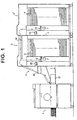
- Figure 1 is a schematic side view showing a sheet sorter provided with a sheet transfer system in accordance with an embodiment of the present invention with the sorter connected to an image recording apparatus,
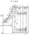
- Figure 2 is a side through-view showing the internal structure of the sorter shown in Figure 1,
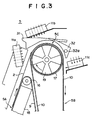
- Figure 3 is a side view showing the bent portion of the conveyance passage of the sheet transfer system of this embodiment, and
- Figure 4 is an exploded perspective view showing the bent portion of the conveyance passage of the sheet transfer system of this embodiment.
- In Figures 1 and 2, a sheet sorter S comprises a plurality of (e.g., fifty) bins (sort trays) 4 which are disposed in fixed positions in a
frame 3 at predetermined intervals in the vertical direction and receive a plurality of recordedsheets 2 discharged from animage recording apparatus 1 such as a printer to form a stack of thesheets 2 on eachbin 4, asheet transfer system 5 which transfers thesheets 2 discharged from theimage recording apparatus 1 toward thebins 4, anindexer 6 which is movable up and down along the array of the sheet inlet ends of thebins 4 and distributes thesheets 2, transferred by thesheet transfer system 5, to therespective bins 4 by a curved guide surface which deflects thesheets 2, and a stapler 7 which is movable up and down along the array of the sheet inlet ends of thebins 4 and in a horizontal direction and staples the stack of sheets on eachbin 4. - In the case where the image recording
apparatus 1 is a printer, especially a stencil printer, a number of sheets can be printed in a short time and recordedsheets 2 carrying thereon wet ink are discharged at a high rate. Accordingly no conveyor roller is used in thesheet transfer system 5 and thesheet transfer system 5 conveys thesheets 2 attracting the back sides thereof under vacuum without contacting the front sides of thesheets 2. - The
sheet transfer system 5 comprises afirst conveyor portion 5A which extends obliquely upward to an upper portion of the sheet sorter S and asecond conveyor portion 5B which vertically extends downward along the path of travel of theindexer 6. The upper portions of the first andsecond conveyor portions bent portion 5C. That is, thesheets 2 discharged from theimage recording apparatus 1 is conveyed obliquely upward to thebent portion 5C by thefirst conveyor portion 5A and delivered to thesecond conveyor portion 5B by way of thebent portion 5C. - The
first conveyor portion 5A basically comprises a pair of perforatedendless conveyor belts 9 each passed around a pair ofpulleys 16 andsuction blowers 8 disposed inside theconveyor belts 9, and conveys thesheets 2 with the back side of thesheets 2 attracted against thebelts 9 under vacuum applied by thesuction blowers 8. Thesecond conveyor portion 5B basically comprises a perforatedendless conveyor belt 10 passed around a pair ofpulleys 17 andsuction blowers 8 disposed inside theconveyor belt 10, and conveys thesheets 2 with the back side of thesheets 2 attracted against thebelt 10 under vacuum applied by thesuction blowers 8. As will be described in detail later with reference to Figure 3 and 4, anair blower 11 blows an air flow against the surface of theconveyor belt 10 at thebent portion 5C, thereby pressing thesheets 2 against the surface of theconveyor belt 10. - In this particular embodiment, the sheet sorter S is arranged so that a plurality of slaves S' having the same structure as the main sheet sorter S can be connected to the sheet sorter S as shown in Figure 1 in order to increase the total number of the
bins 4. The slaves S' are connected to the main sheet sorter S on the side remote from theimage recording apparatus 1. Asheet conveyor 12 is demountably mounted on an upper portion of the main sheet sorter S and thesheets 2 in the main sheet sorter S are transferred to the slaves S' by thesheet conveyor 12 when the slaves S' are connected to the main sheet sorter S. - The
image recording apparatus 1 is provided with asheet tray 13 on which the dischargedsheets 2 are stacked when sorting of thesheets 2 is not necessary. Further acontrol panel 14 and an exteriorelectric stapler 15 are mounted on the outer surface of the sheet sorter S. - As shown in Figure 2, there vertically extend through the plurality of bins 4 a pair of
side lineup rods 21a and 21b which push thesheet 2 in the direction of width of thesheet 2 and bring the side edge of thesheet 2 into abutment against the side edge reference surface, and a trailingedge lineup rod 26 which pushes the leading edge of thesheet 2 to move thesheet 2 toward the sheet inlet end of thebin 4 so that the trailing edge of thesheet 2 is brought into abutment against a trailing edge reference surface defined by ametal web 30 which is fed out from a roll to close the sheet inlet ends of thebins 4 above theindexer 6 in response to a downward movement of theindexer 6 and is taken up around the roll in response to an upward movement of theindexer 6. Asheet stack ejector 25 is mounted on therod 26 to be movable up and down along therod 26. After completion of distribution of thesheets 2 to all thebins 4 by theindexer 6, thesheet stack ejector 25 pushes the sheet stacks 20 on therespective bins 4 to eject them into the path of travel of theindexer 6 for stapling operation. - A specific structure of the
sheet transfer system 5 will be described in detail with reference to Figures 3 and 4, hereinbelow. As shown in Figure 2, thefirst conveyor portion 5A comprises upper and lower sections and the upper and lower sections are substantially the same in structure. Accordingly only the upper section will be described here. As shown in Figure 4, the upper section of thefirst conveyor portion 5A comprises threeperforated conveyor belts 9 each passed around upper and lowersmall diameter pulleys 16. The three uppersmall diameter pulleys 16 are arranged in a row in a direction perpendicular to the sheet conveyance direction at the upper end of thefirst conveyor portion 5A and the three lowersmall diameter pulleys 16 are arranged in a row in a direction perpendicular to the sheet conveyance direction at the lower end of thefirst conveyor portion 5A. Only a part of perforations in theconveyor belts 9 are shown in Figure 4 and only the uppersmall diameter pulleys 16 are shown in Figure 4. A box-like duct 18 is disposed on the back side of theconveyor belts 9. The inside of theduct 18 is kept under vacuum by the suction blowers 8 (Figure 2) and an opening (not shown) is formed in the surface of theduct 18 facing the upper run of theconveyor belts 9 so that thesheet 2 on theconveyor belts 9 is attracted against the front side of thebelts 9 under vacuum. - The
second conveyor portion 5B comprises threeperforated conveyor belts 10 each passed around upper and lowerlarger diameter pulleys 17. The three upperlarger diameter pulleys 17 are arranged in a row in a direction perpendicular to the sheet conveyance direction at the upper end of thesecond conveyor portion 5B or thebent portion 5C and the three lowerlarger diameter pulleys 17 are arranged in a row in a direction perpendicular to the sheet conveyance direction at the lower end of thesecond conveyor portion 5B. Only a part of perforations in theconveyor belts 10 are shown in Figure 4 and only the upperlarger diameter pulleys 17 are shown in Figure 4. Though not shown, a duct similar to theduct 18 of thefirst conveyor portion 5A is disposed on the back side of theconveyor belts 10 so that thesheet 2 on theconveyor belts 10 is attracted against the front side of thebelts 10 under vacuum. Further though not shown, a pair of guide members extend along theconveyor belts 10 among them at thebent portion 5C. - First to third air blower assemblies are arranged in the direction of conveyance around the
bent portion 5C and blow air flows toward the surfaces of theconveyor belts 10 so that thesheet 2 on thebelts 10 is bent along thebent portion 5C by the pressure of the air flows and is conveyed to theindexer 6 by thesecond conveyor portion 5B through thebent portion 5C as theconveyor belts 10 run. - The first air blower assembly is disposed on the first conveyor portion side of the top of the
bent portion 5C and comprises a pair of axialflow air blowers 11a arranged in a direction perpendicular to the conveyance direction. The air flows from theair blowers 11a are directed slightly downstream to give the leading end portion of thesheet 2 approaching thebent portion 5C occasion to bend along thebent portion 5C. - The second air blower assembly is disposed opposed to the top of the
bent portion 5C and comprises three axialflow air blowers 11b arranged in a direction perpendicular to the conveyance direction. The air flows from theair blowers 11b are directed slightly downstream to wind thesheet 2 around thebent portion 5C. The air flow rate of the air flows from the second air blower assembly opposed to the top of thebent portion 5C is larger than those from the other air blower assemblies. - The third air blower assembly is disposed on the second conveyor portion side of the top of the
bent portion 5C and comprises a pair ofcentrifugal air blowers 11c arranged in a direction perpendicular to the conveyance direction. Theair blowers 11c are arranged to blow air flows in their circumferential directions due to spatial limitation. The air flows from theair blowers 11c are directed slightly downstream to keep flat the leading end portion of thesheet 2 along the surfaces of theconveyor belts 10 at the boundary between thebent portion 5C and the flat portion. -
Exhaust fans 19 are provided inside of thebent portion 5C to exhaust air in a direction perpendicular to the direction of conveyance of thesheets 2. - The
exhaust fans 19 are formed by propeller-like arms of the larger diameter pulleys 17 which are rotated about a rotational axis perpendicular to the direction of conveyance of thesheets 2. Theexhaust fans 19 discharge excessive air flow outside the sheet sorter S through a side wall of the sorter S near the back side thereof, thereby preventing a turbulent flow inside thebent portion 5C. - The strength of the air flows blown from the air blower assemblies opposed to the
bent portion 5C is adjustable according to the kind ofsheets 2 to be conveyed. More specifically, the kind ofsheets 2 is determined on the basis of information on the resiliency of thesheets 2 and, for example, the strength of the air flows is increased as the thickness of thesheets 2 increases on the basis of sheet thickness information. - In the
image recording apparatus 1, there is generally provided a manual or automatic adjustment mechanism for adjusting the printing pressure and the like according to the thickness of the sheets. Accordingly it is preferred that the flow rate of the air flows be adjusted on the basis of the sheet thickness information obtained from the adjustment mechanism. - Otherwise the sheet thickness information may be set through an input means such as a control panel provided on the image recording apparatus or the sheet sorter.
- By adjusting the flow rate of the air flows from the air blower assemblies so that the air pressure on the sheets is increased to increase the bending force as the thickness of the sheets increases, thereby bringing the sheets into close contact with the surface of the
conveyor belt 10, and the air pressure on the sheets is reduced as the thickness of the sheets reduces, thereby preventing the back side of the sheets from being pressed against a part other than theconveyor belt 10, the sheets can be successfully conveyed along thebent portion 5C. - An
outer guide member 31 is disposed outside the top of thebent portion 5C in order to prevent thesheets 2 from scattering, for instance, when the air blower assemblies are not operating. Further aflap 32 is mounted for rotation about a pivot pin 32a near thebent portion 5C. Theflap 32 is rotated in the counterclockwise direction in Figure 3 so that its one arm is brought into contact with the upper surface of theconveyor belt 10 when thesheets 2 are to be delivered to thesheet conveyor 12 which transfers thesheets 2 to the slaves S'. - Though, in the embodiment described above, the flow rate of the air blower assemblies is adjusted according to the thickness of the sheets, the flow rate of the air blower assemblies may be adjusted according to the density of the sheets so that the flow rate is increased as the density of the sheets increases. The control means for adjusting the flow rate may be provided either on the image recording apparatus or on the sheet sorter.
Claims (7)
- A sheet transfer system for conveying a sheet along a conveyance passage including a bent portion characterized in that
an air blower means is provided to blow an air flow against a conveyance surface at the bent portion of the conveyance passage so that the sheet is bent along the surface of the conveyance surface. - A sheet transfer system as defined in Claim 1 in which the sheet is conveyed by a conveyor belt which attracts the back side of the sheet under vacuum and the conveyor belt is bent along a pulley at the bent portion of the conveyance passage, said conveyance surface being the upper surface of the conveyor belt.
- A sheet transfer system as defined in Claim 2 further comprising an exhaust fan which exhausts air in a direction perpendicular to the direction of conveyance of the sheet inside of the bent portion of the conveyance passage.
- A sheet transfer system as defined in Claim 3 in which the exhaust fan is provided inside of the pulley along which the conveyor belt is bent and which is rotated about a rotational axis perpendicular to the direction of conveyance of the sheet.
- A sheet transfer system as defined in any one of Claims 1 to 3 in which said air blower means comprises a plurality of air blowers which are arranged in the direction of conveyance around the bent portion with at least one of the air blowers positioned so as to blow an air flow against the top portion of bent portion, and the air flow from said at least one of the air blowers is stronger than those from the other air blowers.
- A sheet transfer system as defined in Claim 1 in which the strength of the air flow blown from the air blower means is adjustable according to the kind of sheet to be conveyed.
- A sheet transfer system as defined in Claim 6 in which the strength of the air flow blown from the air blower means is increased as the thickness of the sheet to be conveyed increases.
Applications Claiming Priority (3)
| Application Number | Priority Date | Filing Date | Title |
|---|---|---|---|
| JP117521/96 | 1996-05-13 | ||
| JP11752196 | 1996-05-13 | ||
| JP11752196A JP3564229B2 (en) | 1996-05-13 | 1996-05-13 | Sheet transport device |
Publications (3)
| Publication Number | Publication Date |
|---|---|
| EP0807593A2 true EP0807593A2 (en) | 1997-11-19 |
| EP0807593A3 EP0807593A3 (en) | 1998-02-04 |
| EP0807593B1 EP0807593B1 (en) | 2003-01-29 |
Family
ID=14713839
Family Applications (1)
| Application Number | Title | Priority Date | Filing Date |
|---|---|---|---|
| EP97107729A Expired - Lifetime EP0807593B1 (en) | 1996-05-13 | 1997-05-12 | Sheet transfer system |
Country Status (4)
| Country | Link |
|---|---|
| US (1) | US5979890A (en) |
| EP (1) | EP0807593B1 (en) |
| JP (1) | JP3564229B2 (en) |
| DE (1) | DE69718701T2 (en) |
Cited By (1)
| Publication number | Priority date | Publication date | Assignee | Title |
|---|---|---|---|---|
| EP2711318A1 (en) * | 2012-09-25 | 2014-03-26 | Multigraf AG | Apparatus and method for conveying sheets and conveyor system |
Families Citing this family (3)
| Publication number | Priority date | Publication date | Assignee | Title |
|---|---|---|---|---|
| US8631928B2 (en) * | 2003-12-15 | 2014-01-21 | Goss International Americas, Inc. | Conveyor for printed sheet material with air assisted drop |
| JP5111155B2 (en) * | 2008-02-26 | 2012-12-26 | デュプロ精工株式会社 | Paper discharge device |
| JP5681221B2 (en) * | 2013-02-26 | 2015-03-04 | 株式会社東芝 | Sheet eraser |
Family Cites Families (13)
| Publication number | Priority date | Publication date | Assignee | Title |
|---|---|---|---|---|
| US2474997A (en) * | 1947-02-21 | 1949-07-05 | Miehle Printing Press & Mfg | Sheet delivery controlling method and means therefor |
| DE2137115A1 (en) * | 1971-07-24 | 1973-02-01 | Maschf Augsburg Nuernberg Ag | BOW CONVEYOR |
| ES203898Y (en) * | 1974-06-12 | 1976-05-16 | Salvat Editores, S. A. | SHEET TURNING MACHINE. |
| US3937459A (en) * | 1974-09-16 | 1976-02-10 | Keith B. Stewart | Sorting machine |
| US4033694A (en) * | 1975-11-17 | 1977-07-05 | Xerox Corporation | Copier document ejector |
| US4285507A (en) * | 1979-01-31 | 1981-08-25 | The Mead Corporation | Ink jet printer |
| DE3411029A1 (en) * | 1984-03-24 | 1985-10-03 | M.A.N.- Roland Druckmaschinen AG, 6050 Offenbach | DEVICE FOR GUIDING SHEETS PRINTED ON SIDE AND BOTH SIDES |
| DD241042A1 (en) * | 1985-09-23 | 1986-11-26 | Polygraph Leipzig | ARC DIRECTION IN PRINTING MACHINES |
| DE4217813C2 (en) * | 1992-05-29 | 1996-06-05 | Heidelberger Druckmasch Ag | Device for achieving a flat installation of printing materials |
| US5379999A (en) * | 1993-07-23 | 1995-01-10 | Eastman Kodak Company | Sheet media handling apparatus |
| US5501147A (en) * | 1993-10-05 | 1996-03-26 | Precision Screen Machines, Inc. | Automatic doffing system |
| DE29501537U1 (en) * | 1995-02-01 | 1995-03-09 | Heidelberger Druckmaschinen Ag, 69115 Heidelberg | Sheet guiding device with air supply boxes |
| US5600906A (en) * | 1995-10-03 | 1997-02-11 | Jet Sew Technologies, Inc. | Automatic suction type transfer of limp material on conveyors |
-
1996
- 1996-05-13 JP JP11752196A patent/JP3564229B2/en not_active Expired - Fee Related
-
1997
- 1997-05-09 US US08/853,591 patent/US5979890A/en not_active Expired - Lifetime
- 1997-05-12 EP EP97107729A patent/EP0807593B1/en not_active Expired - Lifetime
- 1997-05-12 DE DE69718701T patent/DE69718701T2/en not_active Expired - Fee Related
Cited By (2)
| Publication number | Priority date | Publication date | Assignee | Title |
|---|---|---|---|---|
| EP2711318A1 (en) * | 2012-09-25 | 2014-03-26 | Multigraf AG | Apparatus and method for conveying sheets and conveyor system |
| US8998193B2 (en) | 2012-09-25 | 2015-04-07 | Multigraf Ag | Device and method for conveying sheets and conveyor system |
Also Published As
| Publication number | Publication date |
|---|---|
| DE69718701D1 (en) | 2003-03-06 |
| EP0807593A3 (en) | 1998-02-04 |
| US5979890A (en) | 1999-11-09 |
| JPH09301591A (en) | 1997-11-25 |
| DE69718701T2 (en) | 2003-10-09 |
| EP0807593B1 (en) | 2003-01-29 |
| JP3564229B2 (en) | 2004-09-08 |
Similar Documents
| Publication | Publication Date | Title |
|---|---|---|
| CN1122887C (en) | Sheet transfer system | |
| US4887805A (en) | Top vacuum corrugation feeder | |
| CA2172194C (en) | High speed printed sheet stacking and registration system | |
| EP0017983B1 (en) | Sheet transport apparatus | |
| US4789150A (en) | Sheet stacking apparatus with trail edge control flaps | |
| US4572497A (en) | Method and apparatus for collecting form sheets in a set thereof | |
| US5324024A (en) | Paper discharging apparatus | |
| JPH04217274A (en) | Vacuum shutter of plenum of vacuum-platen conveying device | |
| JPH06211402A (en) | Chain conveyor for sheet paper press | |
| US5318285A (en) | Roller/guide plate assembly for ninety degree document transfer unit | |
| JP3891405B2 (en) | Paper feeder | |
| US5979890A (en) | Sheet transfer system | |
| CN111824810B (en) | Media handling between module robustness and paper curl | |
| CN1060133C (en) | Apparatus for seperation of objects | |
| CA1195351A (en) | Sheet inverting device | |
| JP4327978B2 (en) | Paper feeder | |
| JP2024159025A (en) | Sheet separating device and image forming apparatus | |
| EP0864522B1 (en) | Sheet distribution device | |
| JPH10194492A (en) | Sheet feeding apparatus and image forming apparatus | |
| EP0807535B1 (en) | Sheet sorter with stapler | |
| JPH1035927A (en) | Sheet feeding device and sheet processing device | |
| JPH034463B2 (en) | ||
| US12448238B2 (en) | Sheet feeding device | |
| JP3548995B2 (en) | Sheet bundle transport device and image forming machine equipped with the device | |
| JP3189665B2 (en) | Paper sheet stacking device |
Legal Events
| Date | Code | Title | Description |
|---|---|---|---|
| PUAI | Public reference made under article 153(3) epc to a published international application that has entered the european phase |
Free format text: ORIGINAL CODE: 0009012 |
|
| AK | Designated contracting states |
Kind code of ref document: A2 Designated state(s): DE FR GB |
|
| PUAL | Search report despatched |
Free format text: ORIGINAL CODE: 0009013 |
|
| AK | Designated contracting states |
Kind code of ref document: A3 Designated state(s): DE FR GB |
|
| 17P | Request for examination filed |
Effective date: 19980714 |
|
| 17Q | First examination report despatched |
Effective date: 20000605 |
|
| GRAG | Despatch of communication of intention to grant |
Free format text: ORIGINAL CODE: EPIDOS AGRA |
|
| GRAG | Despatch of communication of intention to grant |
Free format text: ORIGINAL CODE: EPIDOS AGRA |
|
| GRAH | Despatch of communication of intention to grant a patent |
Free format text: ORIGINAL CODE: EPIDOS IGRA |
|
| GRAH | Despatch of communication of intention to grant a patent |
Free format text: ORIGINAL CODE: EPIDOS IGRA |
|
| GRAA | (expected) grant |
Free format text: ORIGINAL CODE: 0009210 |
|
| AK | Designated contracting states |
Designated state(s): DE FR GB |
|
| REG | Reference to a national code |
Ref country code: GB Ref legal event code: FG4D |
|
| REF | Corresponds to: |
Ref document number: 69718701 Country of ref document: DE Date of ref document: 20030306 Kind code of ref document: P |
|
| ET | Fr: translation filed | ||
| PLBE | No opposition filed within time limit |
Free format text: ORIGINAL CODE: 0009261 |
|
| STAA | Information on the status of an ep patent application or granted ep patent |
Free format text: STATUS: NO OPPOSITION FILED WITHIN TIME LIMIT |
|
| 26N | No opposition filed |
Effective date: 20031030 |
|
| PGFP | Annual fee paid to national office [announced via postgrant information from national office to epo] |
Ref country code: DE Payment date: 20080515 Year of fee payment: 12 |
|
| PGFP | Annual fee paid to national office [announced via postgrant information from national office to epo] |
Ref country code: GB Payment date: 20080514 Year of fee payment: 12 |
|
| GBPC | Gb: european patent ceased through non-payment of renewal fee |
Effective date: 20090512 |
|
| REG | Reference to a national code |
Ref country code: FR Ref legal event code: ST Effective date: 20100129 |
|
| PG25 | Lapsed in a contracting state [announced via postgrant information from national office to epo] |
Ref country code: FR Free format text: LAPSE BECAUSE OF NON-PAYMENT OF DUE FEES Effective date: 20090602 |
|
| PGFP | Annual fee paid to national office [announced via postgrant information from national office to epo] |
Ref country code: FR Payment date: 20080514 Year of fee payment: 12 |
|
| PG25 | Lapsed in a contracting state [announced via postgrant information from national office to epo] |
Ref country code: GB Free format text: LAPSE BECAUSE OF NON-PAYMENT OF DUE FEES Effective date: 20090512 |
|
| PG25 | Lapsed in a contracting state [announced via postgrant information from national office to epo] |
Ref country code: DE Free format text: LAPSE BECAUSE OF NON-PAYMENT OF DUE FEES Effective date: 20091201 |