EP0807419B1 - Compact external fixator - Google Patents
Compact external fixator Download PDFInfo
- Publication number
- EP0807419B1 EP0807419B1 EP97201442A EP97201442A EP0807419B1 EP 0807419 B1 EP0807419 B1 EP 0807419B1 EP 97201442 A EP97201442 A EP 97201442A EP 97201442 A EP97201442 A EP 97201442A EP 0807419 B1 EP0807419 B1 EP 0807419B1
- Authority
- EP
- European Patent Office
- Prior art keywords
- external fixator
- fixator according
- telescopic
- clamp
- central body
- Prior art date
- Legal status (The legal status is an assumption and is not a legal conclusion. Google has not performed a legal analysis and makes no representation as to the accuracy of the status listed.)
- Expired - Lifetime
Links
- 206010017076 Fracture Diseases 0.000 claims description 19
- 210000000988 bone and bone Anatomy 0.000 claims description 15
- 239000000463 material Substances 0.000 claims description 9
- 230000015572 biosynthetic process Effects 0.000 claims description 8
- 238000005755 formation reaction Methods 0.000 claims description 8
- -1 polysulphonates Polymers 0.000 claims description 4
- 230000006835 compression Effects 0.000 claims description 3
- 238000007906 compression Methods 0.000 claims description 3
- 230000008878 coupling Effects 0.000 claims description 3
- 238000010168 coupling process Methods 0.000 claims description 3
- 238000005859 coupling reaction Methods 0.000 claims description 3
- 229920005992 thermoplastic resin Polymers 0.000 claims description 3
- 239000012780 transparent material Substances 0.000 claims description 3
- 238000003780 insertion Methods 0.000 claims description 2
- 230000037431 insertion Effects 0.000 claims description 2
- 229920000570 polyether Polymers 0.000 claims description 2
- 229920001601 polyetherimide Polymers 0.000 claims description 2
- 229920006324 polyoxymethylene Polymers 0.000 claims description 2
- 239000004411 aluminium Substances 0.000 claims 1
- 229910052782 aluminium Inorganic materials 0.000 claims 1
- XAGFODPZIPBFFR-UHFFFAOYSA-N aluminium Chemical compound [Al] XAGFODPZIPBFFR-UHFFFAOYSA-N 0.000 claims 1
- 230000000295 complement effect Effects 0.000 claims 1
- 230000008774 maternal effect Effects 0.000 claims 1
- 229910001092 metal group alloy Inorganic materials 0.000 claims 1
- 210000000707 wrist Anatomy 0.000 description 4
- 210000003857 wrist joint Anatomy 0.000 description 2
- 229910000838 Al alloy Inorganic materials 0.000 description 1
- 238000007689 inspection Methods 0.000 description 1
- 210000001872 metatarsal bone Anatomy 0.000 description 1
- 238000012986 modification Methods 0.000 description 1
- 230000004048 modification Effects 0.000 description 1
- 229920003023 plastic Polymers 0.000 description 1
- 239000004033 plastic Substances 0.000 description 1
- 238000000926 separation method Methods 0.000 description 1
- 238000001356 surgical procedure Methods 0.000 description 1
Images


Classifications
-
- A—HUMAN NECESSITIES
- A61—MEDICAL OR VETERINARY SCIENCE; HYGIENE
- A61B—DIAGNOSIS; SURGERY; IDENTIFICATION
- A61B17/00—Surgical instruments, devices or methods
- A61B17/56—Surgical instruments or methods for treatment of bones or joints; Devices specially adapted therefor
- A61B17/58—Surgical instruments or methods for treatment of bones or joints; Devices specially adapted therefor for osteosynthesis, e.g. bone plates, screws or setting implements
- A61B17/60—Surgical instruments or methods for treatment of bones or joints; Devices specially adapted therefor for osteosynthesis, e.g. bone plates, screws or setting implements for external osteosynthesis, e.g. distractors, contractors
- A61B17/64—Devices extending alongside the bones to be positioned
- A61B17/6458—Devices extending alongside the bones to be positioned with pin-clamps fixed at ends of connecting element
-
- A—HUMAN NECESSITIES
- A61—MEDICAL OR VETERINARY SCIENCE; HYGIENE
- A61B—DIAGNOSIS; SURGERY; IDENTIFICATION
- A61B17/00—Surgical instruments, devices or methods
- A61B17/56—Surgical instruments or methods for treatment of bones or joints; Devices specially adapted therefor
- A61B17/58—Surgical instruments or methods for treatment of bones or joints; Devices specially adapted therefor for osteosynthesis, e.g. bone plates, screws or setting implements
- A61B17/60—Surgical instruments or methods for treatment of bones or joints; Devices specially adapted therefor for osteosynthesis, e.g. bone plates, screws or setting implements for external osteosynthesis, e.g. distractors, contractors
- A61B17/66—Alignment, compression or distraction mechanisms
-
- A—HUMAN NECESSITIES
- A61—MEDICAL OR VETERINARY SCIENCE; HYGIENE
- A61F—FILTERS IMPLANTABLE INTO BLOOD VESSELS; PROSTHESES; DEVICES PROVIDING PATENCY TO, OR PREVENTING COLLAPSING OF, TUBULAR STRUCTURES OF THE BODY, e.g. STENTS; ORTHOPAEDIC, NURSING OR CONTRACEPTIVE DEVICES; FOMENTATION; TREATMENT OR PROTECTION OF EYES OR EARS; BANDAGES, DRESSINGS OR ABSORBENT PADS; FIRST-AID KITS
- A61F2/00—Filters implantable into blood vessels; Prostheses, i.e. artificial substitutes or replacements for parts of the body; Appliances for connecting them with the body; Devices providing patency to, or preventing collapsing of, tubular structures of the body, e.g. stents
- A61F2/02—Prostheses implantable into the body
- A61F2/30—Joints
- A61F2002/30001—Additional features of subject-matter classified in A61F2/28, A61F2/30 and subgroups thereof
- A61F2002/30003—Material related properties of the prosthesis or of a coating on the prosthesis
- A61F2002/3006—Properties of materials and coating materials
- A61F2002/3008—Properties of materials and coating materials radio-opaque, e.g. radio-opaque markers
-
- A—HUMAN NECESSITIES
- A61—MEDICAL OR VETERINARY SCIENCE; HYGIENE
- A61F—FILTERS IMPLANTABLE INTO BLOOD VESSELS; PROSTHESES; DEVICES PROVIDING PATENCY TO, OR PREVENTING COLLAPSING OF, TUBULAR STRUCTURES OF THE BODY, e.g. STENTS; ORTHOPAEDIC, NURSING OR CONTRACEPTIVE DEVICES; FOMENTATION; TREATMENT OR PROTECTION OF EYES OR EARS; BANDAGES, DRESSINGS OR ABSORBENT PADS; FIRST-AID KITS
- A61F2250/00—Special features of prostheses classified in groups A61F2/00 - A61F2/26 or A61F2/82 or A61F9/00 or A61F11/00 or subgroups thereof
- A61F2250/0058—Additional features; Implant or prostheses properties not otherwise provided for
- A61F2250/0096—Markers and sensors for detecting a position or changes of a position of an implant, e.g. RF sensors, ultrasound markers
- A61F2250/0098—Markers and sensors for detecting a position or changes of a position of an implant, e.g. RF sensors, ultrasound markers radio-opaque, e.g. radio-opaque markers
Definitions
- This invention relates to an external fixator which can be used in the field of bone surgery and in particular for the treatment of fractures in small bones, such as fractures of the first metatarsal, the wrist, the heel, and in general fractures in the bones of small children.
- Small axial external fixators such as for example the external axial fixator model no. 30000 produced and marketed by the applicant and described and claimed in European patent no. 11,258 and in US patent 4,621,627 are known.
- fixators generally comprise an elongatable central body with clamps attached to the longitudinal ends thereof by means of pins or bone bolts through corresponding ball joints which can be immobilised in a predetermined orientation.
- Each joint comprises a ball formation which is integral with a clamp or the central body and is acted upon by a locking bush pushed by an eccentric which can be rotated from the exterior by means of a suitable tool.
- the central body comprises two or more telescopic members which can move with respect to each other and which can be immobilised in the required position by means of suitable locking members.
- the form of fixator described above is produced in several sizes, one of which is used to reduce and stabilise fractures in small children and in the smallest bones of adults, such as for example the wrist or heel.
- fixators lies in their bulkiness, due to the fact that the stop blocks and eccentric locking devices are placed between the central body and the corresponding clamps, and therefore increases the length of the fixator and the minimum distance between the bone bolts, reducing the possibilities for adjustment of the central body.
- a further disadvantage lies in the relatively large weight of conventional fixators, especially when treating fractures of the wrist and in general fractures in small children and old people.
- Yet another disadvantage lies in the possibility of relative torsion between the telescopic part of cylindrical shape about their longitudinal axis when these parts are not immobilised to allow limited movement of the stumps, and to accelerate new marginal growth in the fracture.
- WO 9423662 discloses an external fixator whose central body comprises a male and a female member, both made of plastics material, i.e. an X-rays transparent material.
- WO 94-06364 discloses an external fixator with two telescoping members with adequate X-ray transparency.
- the main object of the present invention is to eliminate the aforementioned disadvantages by providing an external fixator which permits X-ray examination of the fracture from all viewpoints, including therefore through the fixator, while showing, at the same time, reliable characteristics in respect of torsional rigidity and immobilisation of the orientation of the joints.
- a further object is to provide an external fixator which is particularly suitable for the treatment of fractures in the small bones of adults and in general in. the bones of small children.
- Another object is to provide a fixator which has the feature of being appreciably light.
- an external axial fixator according to the invention, indicated in general by reference number 1, comprises a pair of clamps 2, 3 for securing bolts or pins V which have been first fixed by the surgeon in the stumps of the fracture, for example in the wrist joint, connected to a central elongatable body 4 by means of corresponding end joints 5, 6.
- Central body 4 may be formed of two members, respectively one male member 7 and one female member 8, of an approximately cylindrical shape, having a circular transverse cross-section, which are telescopically coupled in such a way that they can slide over each other along a common longitudinal axis L varying the overall length of central body 4.
- Clamps 2, 3 are preferably formed of corresponding principal portions 9, 10 of approximately prismatic or parallelepiped shape connected to corresponding plates 11, 12 by means of bolts 13, 14 to secure bone pins V.
- telescopic members 7, 8 are at least partly X-rays transparent to allow viewing of the fracture even through central body 4.
- One of the telescopic members, in particular male member 7, is made of a material which is highly X-rays transparent.
- the highly X-rays transparent material may be a thermoplastic resin with an amorphous or semicrystalline structure selected from the polyethers, polysulphonates, polyoxymethylenes or polyetherimides.
- female telescopic member 8 is constructed of a material which is substantially opaque to X-rays, such as for example an aluminium alloy, and has lateral walls of a relatively reduced thickness such as to be at least partly X-rays transparent.
- male telescopic member 7 has a flat 15 which extends over almost its entire length, leaving an end projection 16.
- female member 8 has a lateral projection 17 in which a partly threaded hole is provided to house a transverse screw 18 of which the smooth part acts together with longitudinal flat 15 of member 7 to prevent rotation of the latter about longitudinal axis L.
- lateral projection 17 has a central slit 19 of predetermined length so as to provide the end of female member 8 with a certain amount of radial resiliency.
- Bolt 18 which passes through lateral projection 17 can tighten the end of female member 8 immobilising male member 7 in the required position.
- bolt 18 comprises an end stop with respect to end projection 16, preventing involuntary separation between member 7 and member 8.
- main prismatic portions 9, 10 of both clamps 2, 3 have axial through cavities 20, 21 with corresponding spherical restrictions 22, 23 which interact with ball joints 24, 25 fixed to corresponding telescopic members 7, 8 by means of locking screws 26, 27.
- Locking cylindrical blocks 28, 29 are housed in through cavities 20, 21 and have at one end hemispherical seats 30, 31 acting against ball joints 24, 25 and at the opposite end cylindrical diametric seats 32, 33 facing outwards.
- Transverse eccentric pins 34, 35 are rotatably supported at the distal ends of principal portions 9, 10 of clamps 2, 3 so as to interact with corresponding locking blocks 28, 29 on their diametric seats 32, 33.
- By rotating eccentrics 34, 35 hemispherical seats 30, 31 of the blocks are forced against the opposing ball joints 24, 25 in such a way as to immobilise them in the desired orientation.
- a reduction in the overall length of the fixator is achieved through this arrangement of the eccentrics on the clamps, in particular towards their outer ends, making use of the structure of the clamp itself.
- the maximum distance between the clamps, and therefore between bone bolts V is less than in the past, permitting optimum use of the fixator for the wrist joint, and in general for small bones and in children.
- a tensioning device which is generally indicated with the reference number 36 and is clearly illustrated in Fig. 11-13.
- Tensioning device 36 comprises a sleeve 37 with a longitudinal axis M which has a substantially cylindrical expansion 38 formed on the outer surface thereof and provided with longitudinal gripping grooves 39 and with a central hole 40 for insertion of a pin-like tool to allow rotation of the sleeve 37.
- the end portions 41, 42 of the sleeve are internally threaded with opposite threads to receive corresponding threaded rods 43, 44 carrying at the opposite ends thereof securing means 45, 46 for rigidly coupling with fixator 1.
- Securing means 45, 46 are essentially formed by approximately prismatic supports 47, 48 from which hook formations 49, 50 with centres equidistant from the axis M extend.
- Hook formations 49, 50 can be easily inserted into cylindrical grooves 51, 52 formed at the outer ends of telescopic members 7, 8 of central body 4 in such a manner that axis M of the tensioning device lays substantially parallel to axis L of the fixator 1.
- Securing means 45, 46 are rigidly coupled to fixator 1 by means of corresponding screws 53, 54 passing through transverse holes of supports 47, 48 having axis directed towards the centres of their hook formations 49, 50.
- a distraction or compression of the focus can be exerted by means of tensioning device 36, specifically by inserting hook formations 49, 50 into the cylindrical grooves 51, 52 of the telescopic members 7, 8.
- the sleeve 37 can be rotated acting either with the fingers on the expansion 38 or with a pin-like tool on the central hole 40 to bring threaded rods 43, 44 closer or further away as much as needed.
- the tensioning device can be coupled to the fixator in an extremely easy manner thanks to the open structure of the hook formation of the securing means that facilitates the use of the device even in a narrow space.
- the fixator according to the invention is susceptible of many modifications and variants which fall within the scope of the appended claims. Dimensions, shapes and materials may be altered without going beyond the scope of the invention.
Landscapes
- Health & Medical Sciences (AREA)
- Orthopedic Medicine & Surgery (AREA)
- Life Sciences & Earth Sciences (AREA)
- Surgery (AREA)
- Medical Informatics (AREA)
- General Health & Medical Sciences (AREA)
- Biomedical Technology (AREA)
- Heart & Thoracic Surgery (AREA)
- Nuclear Medicine, Radiotherapy & Molecular Imaging (AREA)
- Molecular Biology (AREA)
- Animal Behavior & Ethology (AREA)
- Engineering & Computer Science (AREA)
- Public Health (AREA)
- Veterinary Medicine (AREA)
- Surgical Instruments (AREA)
- Apparatus For Radiation Diagnosis (AREA)
- Clamps And Clips (AREA)
- Glass Compositions (AREA)
Description
- This invention relates to an external fixator which can be used in the field of bone surgery and in particular for the treatment of fractures in small bones, such as fractures of the first metatarsal, the wrist, the heel, and in general fractures in the bones of small children.
- Small axial external fixators such as for example the external axial fixator model no. 30000 produced and marketed by the applicant and described and claimed in European patent no. 11,258 and in US patent 4,621,627 are known.
- These known fixators generally comprise an elongatable central body with clamps attached to the longitudinal ends thereof by means of pins or bone bolts through corresponding ball joints which can be immobilised in a predetermined orientation. Each joint comprises a ball formation which is integral with a clamp or the central body and is acted upon by a locking bush pushed by an eccentric which can be rotated from the exterior by means of a suitable tool. The central body comprises two or more telescopic members which can move with respect to each other and which can be immobilised in the required position by means of suitable locking members. The form of fixator described above is produced in several sizes, one of which is used to reduce and stabilise fractures in small children and in the smallest bones of adults, such as for example the wrist or heel.
- However, even this type of fixator has some recognised disadvantages, among which should be mentioned in particular the opacity of the central body to X-rays, which prevents multilateral X-rays examination of fractures during reduction and in the course of subsequent inspections.
- Another disadvantage of known fixators lies in their bulkiness, due to the fact that the stop blocks and eccentric locking devices are placed between the central body and the corresponding clamps, and therefore increases the length of the fixator and the minimum distance between the bone bolts, reducing the possibilities for adjustment of the central body.
- A further disadvantage lies in the relatively large weight of conventional fixators, especially when treating fractures of the wrist and in general fractures in small children and old people.
- Yet another disadvantage lies in the possibility of relative torsion between the telescopic part of cylindrical shape about their longitudinal axis when these parts are not immobilised to allow limited movement of the stumps, and to accelerate new marginal growth in the fracture.
- WO 9423662 discloses an external fixator whose central body comprises a male and a female member, both made of plastics material, i.e. an X-rays transparent material.
- WO 94-06364 discloses an external fixator with two telescoping members with adequate X-ray transparency.
- The main object of the present invention is to eliminate the aforementioned disadvantages by providing an external fixator which permits X-ray examination of the fracture from all viewpoints, including therefore through the fixator, while showing, at the same time, reliable characteristics in respect of torsional rigidity and immobilisation of the orientation of the joints.
- A further object is to provide an external fixator which is particularly suitable for the treatment of fractures in the small bones of adults and in general in. the bones of small children.
- Another object is to provide a fixator which has the feature of being appreciably light.
- These and other objects are achieved by an external fixator according to the appended claims.
- Further features and advantages will be more apparent in the light of the detailed description of a preferred but non-exclusive embodiment of the external fixator according to the invention which is illustrated by way of a non-restrictive example with reference to the appended table of drawings in which:
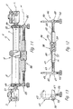
- Fig.1 shows a general perspective view of an external fixator according to the invention fitted in the vicinity of an articulation of the wrist ;
- Fig.2 represents a side elevation view of the fixator in Fig. 1 in the fully retracted position;
- Fig. 3 illustrates a side elevation view of the fixator in Fig. 1 in the fully extended position ;
- Fig. 4 shows a side view of a first detail of the above figures in partial cross-section along an axial longitudinal plane ;
- Fig. 5 shows a side view of a second detail of the above figures partly in cross-section along an axial longitudinal plane;
- Fig. 6 shows a view in transverse cross-section along the plane of the line VI-VI of the detail in Fig. 4 ;
- Fig. 7 shows a view in transverse cross-section along the plane of line VII-VII in the detail of Fig. 5 ;
- Fig. 8 shows a view in transverse cross-section along the plane of line VIII-VIII in the detail of Fig. 5 ;
- Fig. 9 shows an exploded view in partial cross-section along an axial plane of a clamp in Fig. 4 ;
- Fig. 10 shows a perspective view of a detail of the clamp in Fig. 9 ;
- Fig. 11 shows a side view of the fixator of Fig. 1 coupled to a tensioning device ;
- Fig. 12 shows a side view of the independent tensioning device of Fig. 11;
- Fig. 13 is a front view of the tensioning device of Fig. 12.
-
- With reference to the aforesaid figures, an external axial fixator according to the invention, indicated in general by
reference number 1, comprises a pair ofclamps elongatable body 4 by means ofcorresponding end joints -
Central body 4 may be formed of two members, respectively onemale member 7 and onefemale member 8, of an approximately cylindrical shape, having a circular transverse cross-section, which are telescopically coupled in such a way that they can slide over each other along a common longitudinal axis L varying the overall length ofcentral body 4. -
Clamps principal portions corresponding plates bolts - According to the invention,
telescopic members central body 4. One of the telescopic members, in particularmale member 7, is made of a material which is highly X-rays transparent. - The highly X-rays transparent material may be a thermoplastic resin with an amorphous or semicrystalline structure selected from the polyethers, polysulphonates, polyoxymethylenes or polyetherimides.
Preferably femaletelescopic member 8 is constructed of a material which is substantially opaque to X-rays, such as for example an aluminium alloy, and has lateral walls of a relatively reduced thickness such as to be at least partly X-rays transparent. - From calculations and tests it has been possible to show that if a female
telescopic member 8 is constructed with lateral walls of thickness S not exceeding approximately 1 mm then the central body as a whole becomes sufficiently X-rays transparent. - In order to prevent the relative rotation of
telescopic members bone clamps
In particular, maletelescopic member 7 has a flat 15 which extends over almost its entire length, leaving an end projection 16. - At the free end
opposite clamp 3,female member 8 has alateral projection 17 in which a partly threaded hole is provided to house atransverse screw 18 of which the smooth part acts together with longitudinal flat 15 ofmember 7 to prevent rotation of the latter about longitudinal axis L. - Appropriately,
lateral projection 17 has acentral slit 19 of predetermined length so as to provide the end offemale member 8 with a certain amount of radial resiliency.Bolt 18 which passes throughlateral projection 17 can tighten the end offemale member 8 immobilisingmale member 7 in the required position. In addition to this,bolt 18 comprises an end stop with respect to end projection 16, preventing involuntary separation betweenmember 7 andmember 8. - It will be noted that the main
prismatic portions clamps cavities 20, 21 with correspondingspherical restrictions ball joints telescopic members locking screws
Lockingcylindrical blocks cavities 20, 21 and have at one endhemispherical seats ball joints diametric seats 32, 33 facing outwards. - Transverse
eccentric pins principal portions clamps corresponding locking blocks diametric seats 32, 33. By rotatingeccentrics hemispherical seats opposing ball joints - A reduction in the overall length of the fixator is achieved through this arrangement of the eccentrics on the clamps, in particular towards their outer ends, making use of the structure of the clamp itself. Thus the maximum distance between the clamps, and therefore between bone bolts V, is less than in the past, permitting optimum use of the fixator for the wrist joint, and in general for small bones and in children.
- In order to allow a distraction or compression of the
fracture fixator 1 is provided with means for coupling to a tensioning device which is generally indicated with thereference number 36 and is clearly illustrated in Fig. 11-13. -
Tensioning device 36 comprises asleeve 37 with a longitudinal axis M which has a substantiallycylindrical expansion 38 formed on the outer surface thereof and provided withlongitudinal gripping grooves 39 and with acentral hole 40 for insertion of a pin-like tool to allow rotation of thesleeve 37. Theend portions 41, 42 of the sleeve are internally threaded with opposite threads to receive corresponding threadedrods fixator 1. Securing means 45, 46 are essentially formed by approximatelyprismatic supports hook formations Hook formations cylindrical grooves telescopic members central body 4 in such a manner that axis M of the tensioning device lays substantially parallel to axis L of thefixator 1. - Securing means 45, 46 are rigidly coupled to
fixator 1 by means ofcorresponding screws supports hook formations - The use of the fixator will be obvious in the light of the foregoing description.
- After bolts V have been fitted into the stumps of the fracture,
bolts eccentrics stop screw 18 in the central body are released. After this the length of the fixator is adjusted in such a way that bolts V are inserted betweenplates principal portions bolts eccentrics - Once the fracture has been reduced a distraction or compression of the focus can be exerted by means of tensioning
device 36, specifically by insertinghook formations cylindrical grooves telescopic members sleeve 37 can be rotated acting either with the fingers on theexpansion 38 or with a pin-like tool on thecentral hole 40 to bring threadedrods - As a result of the X-ray transparency of the central body it is possible to perform the entire operation of reducing the fracture, exposing it to X-rays even from the side on which the fixator is located, with greater ease of handling and a reduction in exposure times.
- The tensioning device can be coupled to the fixator in an extremely easy manner thanks to the open structure of the hook formation of the securing means that facilitates the use of the device even in a narrow space.
The fixator according to the invention is susceptible of many modifications and variants which fall within the scope of the appended claims. Dimensions, shapes and materials may be altered without going beyond the scope of the invention.
Claims (17)
- A compact external fixator which is particularly suitable for the treatment of fractures in small bones and in small children, comprising a pair of clamps (2, 3) for bone bolts (V) connected by means of immobilisable ball joints (5, 6) to a central body (4) of adjustable length comprising at least one male member (7) and one female member (8) which are attached telescopically, characterised in that one of the said telescopic members is constructed of a material which is highly X-rays transparent and the other of the said telescopic members is constructed of a substantially radio-opaque rigid material having lateral walls of a thickness (S) which is reduced so that they are at least partly X-rays transparent, so as to permit radioscopy of the fracture through the central body (4).
- An external fixator according to claim 1, in which the said highly X-rays transparent material is a thermoplastic resin with an amorphous or semicrystalline structure.
- An external fixator according to claim 2, in which the said thermoplastic resin is selected from polyethers, polysulphonates, polyoxymethylenes or polyetherimides.
- An external fixator according to claim 1, in which the said substantially radio-opaque material is an aluminium-based metal alloy.
- An external fixator according to any one of the preceding claims, in which said telescopic member (8) constructed of a substantially radio-opaque rigid material is the female member.
- An external fixator according to claim 5, in which the wall of the said member (8) of radio-opaque material has a maximum thickness of approximately 1 mm.
- An external fixator according to claim 1, in which means (7, 15, 17, 18) are provided for immobilising rotation between the male telescopic member (7) and the female member (8).
- An external fixator according to claim 7, in which the said means immobilising rotation comprise a longitudinal flap (15) formed on the male telescopic member (7) which has a substantially circular transverse cross-section.
- An external fixator according to claim 8, in which the said means immobilising rotation comprise a lateral projection (17) formed at the end of the female telescopic member (8) opposite the corresponding clamp and designed to house a transverse immobilising screw (18) which interacts with the longitudinal flat (15) on the male telescopic member (7) in such a way as to prevent rotation of the latter about the longitudinal axis (L) of the central body.
- An external fixator according to claim 9, in which the said lateral projection (17) has a longitudinal central part (19) which confers radial elasticity on the end of the telescopic member (8) in which it is formed, and the said end can be resiliently closed by means of the said securing screw ( 18) to selectively immobilise the male telescopic member (7).
- An external fixator according to claim 1, in which each clamp (2, 3) comprises a substantially prismatic principal portion (9, 10) with an axial through cavity (20, 21) in which a ball joint (24, 25) attached to a corresponding telescopic member (7, 8) is housed.
- An external clamp according to claim 11, in which a stop block (28, 29) is inserted into a corresponding axial through cavity (20, 21), the said block (28, 29) having a first substantially hemispherical seat (30, 31) at one longitudinal end which is capable of interacting with a corresponding ball joint (24, 25) and at the opposite end a diametric cylindrical seat (32, 33).
- An maternal fixator according to claim 12, in which a transverse eccentric pin (34, 35) is rotatably supported at the outer end of each clamp (2, 3) to interact with a corresponding block (28, 29) on the diametric seat (32, 33) of the latter to immobilise the said ball joint (24, 25).
- An external fixator according to claim 1, in which each clamp (2, 3) comprises a plate (11, 12) which can be anchored to the said principal portion (9, 10) in order to immobilise one or more transverse bone bolts (V) with the latter.
- An external fixator according to claim 1, in which said central body (4) has means for removable coupling to a tensioning device (36) for exerting a distraction or compression on the fracture.
- An external fixator according to claim 15, in which said tensioning device (36) comprises a pair of securing means (45, 46) attached to the ends of corresponding counter-threaded rods (43, 44) screwed in end portions (41, 42) of a rotatable sleeve (37).
- An external fixator according to claim 16, in which said securing means (45, 46) have hook formations (49, 50) for insertion in complementary shaped grooves (51, 52) formed at the opposite ends of said telescopic members (7, 8) and corresponding locking screws (53, 54) acting towards the centres of said hook formations (49, 50).
Applications Claiming Priority (2)
| Application Number | Priority Date | Filing Date | Title |
|---|---|---|---|
| ITVR960044 | 1996-05-15 | ||
| IT96VR000044A IT1289103B1 (en) | 1996-05-15 | 1996-05-15 | COMPACT EXTERNAL FIXER |
Publications (3)
| Publication Number | Publication Date |
|---|---|
| EP0807419A2 EP0807419A2 (en) | 1997-11-19 |
| EP0807419A3 EP0807419A3 (en) | 1998-04-08 |
| EP0807419B1 true EP0807419B1 (en) | 2002-08-14 |
Family
ID=11428190
Family Applications (1)
| Application Number | Title | Priority Date | Filing Date |
|---|---|---|---|
| EP97201442A Expired - Lifetime EP0807419B1 (en) | 1996-05-15 | 1997-05-13 | Compact external fixator |
Country Status (12)
| Country | Link |
|---|---|
| US (1) | US5951556A (en) |
| EP (1) | EP0807419B1 (en) |
| JP (1) | JPH1043204A (en) |
| AR (1) | AR013567A1 (en) |
| AT (1) | ATE222078T1 (en) |
| AU (1) | AU722193B2 (en) |
| DE (1) | DE69714645T2 (en) |
| DK (1) | DK0807419T3 (en) |
| ES (1) | ES2180000T3 (en) |
| IT (1) | IT1289103B1 (en) |
| PT (1) | PT807419E (en) |
| ZA (1) | ZA974144B (en) |
Families Citing this family (126)
| Publication number | Priority date | Publication date | Assignee | Title |
|---|---|---|---|---|
| CA2332557C (en) | 1998-05-19 | 2007-04-17 | Synthes (U.S.A.) | Telescopic body for an external fixation system |
| JP2002515286A (en) | 1998-05-19 | 2002-05-28 | ジンテーズ アクチエンゲゼルシャフト クール | Jaw for unilateral external fixation system for trauma and orthopedics |
| DK1284666T3 (en) * | 2000-05-26 | 2007-05-07 | Orthofix Srl | Exterior disposable fixing device |
| EP1157664B1 (en) * | 2000-05-26 | 2004-09-22 | Orthofix International B.V. | Improved axial external fixator |
| RU2314766C2 (en) * | 2001-02-26 | 2008-01-20 | Государственное учреждение Российский научный центр "Восстановительная травматология и ортопедия" им. акад. Г.А. Илизарова | Locator for wrist and for bones |
| DK1238636T3 (en) * | 2001-03-05 | 2007-01-02 | Orthofix Srl | Exterior fastener with ID |
| KR100426565B1 (en) * | 2001-05-04 | 2004-04-08 | 메딕스얼라인 주식회사 | apparatus for adjusting an external fixator |
| ITBO20010310A1 (en) * | 2001-05-18 | 2002-11-18 | Agenzia Spaziale Italiana | EXTERNAL BONE FIXER |
| US7261713B2 (en) | 2001-10-09 | 2007-08-28 | Synthes (Usa) | Adjustable fixator |
| US6709433B1 (en) | 2001-12-20 | 2004-03-23 | Biomet, Inc. | Bridging/non-bridging external bone fixator |
| EP1549235A4 (en) * | 2002-09-17 | 2010-05-05 | Extraortho Inc | Unilateral fixator |
| US20040068263A1 (en) * | 2002-10-04 | 2004-04-08 | Benoit Chouinard | CAS bone reference with articulated support |
| JP4505333B2 (en) * | 2002-11-14 | 2010-07-21 | エクストラオルト インコーポレイテッド | How to use a fixator device |
| US7918876B2 (en) | 2003-03-24 | 2011-04-05 | Theken Spine, Llc | Spinal implant adjustment device |
| US7645279B1 (en) | 2003-07-25 | 2010-01-12 | Haupt Bruce F | Bone fixation method |
| AU2004317510A1 (en) * | 2004-03-10 | 2005-10-06 | Synthes Gmbh | External fixer for osteosynthesis |
| ATE470460T1 (en) * | 2004-04-19 | 2010-06-15 | Synthes Gmbh | ELASTIC ELEMENT MADE OF AN X-RAY TRANSMITTER MATERIAL FOR A MEDICAL DEVICE |
| US7544208B1 (en) | 2004-05-03 | 2009-06-09 | Theken Spine, Llc | Adjustable corpectomy apparatus |
| US7828801B2 (en) * | 2004-09-03 | 2010-11-09 | A.M. Surgical, Inc. | External fixation device for fractures |
| US8262656B2 (en) * | 2004-09-03 | 2012-09-11 | A.M. Surgical, Inc. | External fixation device for fractures |
| RU2282415C1 (en) * | 2005-02-14 | 2006-08-27 | ГОУ ВПО "Саратовский государственный университет им. Н.Г. Чернышевского" | Device for carrying out external fixation |
| RU2281716C1 (en) * | 2005-02-14 | 2006-08-20 | ГОУ ВПО "Саратовский государственный университет им. Н.Г. Чернышевского" | External fixation apparatus |
| RU2281054C1 (en) * | 2005-02-14 | 2006-08-10 | ГОУ ВПО "Саратовский государственный университет им. Н.Г. Чернышевского" | External fixation apparatus |
| US7588571B2 (en) | 2005-03-18 | 2009-09-15 | Ron Anthon Olsen | Adjustable splint for osteosynthesis with modular joint |
| US8758343B2 (en) | 2005-04-27 | 2014-06-24 | DePuy Synthes Products, LLC | Bone fixation apparatus |
| US7846162B2 (en) | 2005-05-18 | 2010-12-07 | Sonoma Orthopedic Products, Inc. | Minimally invasive actuable bone fixation devices |
| US9060820B2 (en) | 2005-05-18 | 2015-06-23 | Sonoma Orthopedic Products, Inc. | Segmented intramedullary fracture fixation devices and methods |
| US8961516B2 (en) | 2005-05-18 | 2015-02-24 | Sonoma Orthopedic Products, Inc. | Straight intramedullary fracture fixation devices and methods |
| US7731738B2 (en) | 2005-12-09 | 2010-06-08 | Orthopro, Llc | Cannulated screw |
| RU2306897C1 (en) * | 2006-04-20 | 2007-09-27 | ГОУ ВПО "Саратовский государственный университет имени Н.Г. Чернышевского" | External fixation apparatus |
| WO2007138659A1 (en) * | 2006-05-26 | 2007-12-06 | National University Corporation Nagoya University | External fixator |
| CA2670263A1 (en) | 2006-11-22 | 2008-05-29 | Sonoma Orthopedic Products, Inc. | Fracture fixation device, tools and methods |
| US7981116B2 (en) * | 2007-05-25 | 2011-07-19 | Custom Spine, Inc. | Radiolucent screwdriver for orthopedic surgery |
| NL1033925C2 (en) * | 2007-06-01 | 2008-12-02 | Umc Utrecht Holding Bv | System for correcting bones. |
| US8313515B2 (en) | 2007-06-15 | 2012-11-20 | Rachiotek, Llc | Multi-level spinal stabilization system |
| US8147491B2 (en) | 2007-06-27 | 2012-04-03 | Vilex In Tennessee, Inc. | Multi-angle clamp |
| JP5602633B2 (en) | 2007-10-31 | 2014-10-08 | ライト メディカル テクノロジー インコーポレイテッド | Orthopedic equipment |
| CN103271761B (en) | 2008-01-14 | 2015-10-28 | 康文图斯整形外科公司 | For the apparatus and method of fracture repair |
| EP2299917A1 (en) | 2008-06-10 | 2011-03-30 | Sonoma Orthopedic Products, Inc. | Fracture fixation device, tools and methods |
| CH702239B1 (en) * | 2008-06-17 | 2011-05-31 | Kai-Uwe Lorenz | An apparatus for external fixation of bone fractures. |
| IT1391222B1 (en) * | 2008-09-11 | 2011-12-01 | Orthofix Srl | ORTHOPEDIC DEVICE TO BE ASSOCIATED WITH A BONE |
| US9408649B2 (en) * | 2008-09-11 | 2016-08-09 | Innovasis, Inc. | Radiolucent screw with radiopaque marker |
| AU2009296243A1 (en) | 2008-09-26 | 2010-04-01 | Sonoma Orthopedic Products, Inc. | Bone fixation device, tools and methods |
| US9433439B2 (en) * | 2009-09-10 | 2016-09-06 | Innovasis, Inc. | Radiolucent stabilizing rod with radiopaque marker |
| WO2011088172A1 (en) | 2010-01-15 | 2011-07-21 | Brenzel Michael P | Rotary-rigid orthopaedic rod |
| EP2523616B1 (en) | 2010-01-20 | 2019-04-17 | Conventus Orthopaedics, Inc. | Apparatus for bone access and cavity preparation |
| JP2013521880A (en) | 2010-03-08 | 2013-06-13 | コンベンタス オーソピディックス, インコーポレイテッド | Apparatus and method for securing a bone implant |
| US8801712B2 (en) * | 2010-03-08 | 2014-08-12 | Innovasis, Inc. | Radiolucent bone plate with radiopaque marker |
| GB201008281D0 (en) | 2010-05-19 | 2010-06-30 | Nikonovas Arkadijus | Indirect analysis and manipulation of objects |
| US8721566B2 (en) * | 2010-11-12 | 2014-05-13 | Robert A. Connor | Spinal motion measurement device |
| RU2485905C2 (en) * | 2011-04-05 | 2013-06-27 | Государственное образовательное учреждение высшего профессионального образования "Дагестанская государственная медицинская академия федерального агентства по здравоохранению и социальному развитию" | Device for extrafocal rod osteosynthesis of fractures of long tubular bones |
| US9301782B2 (en) | 2012-09-04 | 2016-04-05 | Zimmer, Inc. | External fixation |
| US9924969B2 (en) | 2012-09-04 | 2018-03-27 | Zimmer, Inc. | External fixation |
| ITVR20130013A1 (en) * | 2013-01-21 | 2014-07-22 | Tecres Spa | EXTERNAL FIXING DEVICE FOR THE TREATMENT OF BONE FRACTURES |
| US9675382B2 (en) | 2013-03-13 | 2017-06-13 | DePuy Synthes Products, Inc. | External bone fixation device |
| US8864763B2 (en) | 2013-03-13 | 2014-10-21 | DePuy Synthes Products, LLC | External bone fixation device |
| US9039706B2 (en) | 2013-03-13 | 2015-05-26 | DePuy Synthes Products, Inc. | External bone fixation device |
| US9468479B2 (en) | 2013-09-06 | 2016-10-18 | Cardinal Health 247, Inc. | Bone plate |
| JP6539652B2 (en) | 2013-12-12 | 2019-07-03 | コンベンタス オーソピディックス, インコーポレイテッド | Tissue displacement tools and methods |
| US9770278B2 (en) | 2014-01-17 | 2017-09-26 | Arthrex, Inc. | Dual tip guide wire |
| WO2015183226A2 (en) * | 2014-05-27 | 2015-12-03 | Spi̇namer Sağlik Ürünleri̇ Sanayi̇ Ve Teknoloji̇ Li̇mi̇ted Şi̇rketi̇ | Unilateral bone fixator system enabling bone extension and three dimensional fixation |
| US20160015426A1 (en) | 2014-07-15 | 2016-01-21 | Treace Medical Concepts, Inc. | Bone positioning and cutting system and method |
| US10314618B2 (en) * | 2014-07-25 | 2019-06-11 | The General Hospital Corporation | System and method for an external hip fixator |
| US9962187B2 (en) | 2014-08-11 | 2018-05-08 | Zimmer, Inc. | External fixation |
| US9814499B2 (en) | 2014-09-30 | 2017-11-14 | Arthrex, Inc. | Intramedullary fracture fixation devices and methods |
| CN106236226B (en) * | 2014-10-24 | 2019-08-09 | 中南大学湘雅三医院 | A coil-spring external fixator adaptable to comminuted fractures |
| US9687250B2 (en) | 2015-01-07 | 2017-06-27 | Treace Medical Concepts, Inc. | Bone cutting guide systems and methods |
| US10849631B2 (en) | 2015-02-18 | 2020-12-01 | Treace Medical Concepts, Inc. | Pivotable bone cutting guide useful for bone realignment and compression techniques |
| US10653467B2 (en) | 2015-05-06 | 2020-05-19 | Treace Medical Concepts, Inc. | Intra-osseous plate system and method |
| WO2016205128A2 (en) | 2015-06-17 | 2016-12-22 | Nathan Erickson | Ankle fixation system |
| CA3281165A1 (en) | 2015-07-14 | 2025-10-31 | Treace Medical Concepts, Inc. | Bone positioning guide |
| US9622805B2 (en) | 2015-08-14 | 2017-04-18 | Treace Medical Concepts, Inc. | Bone positioning and preparing guide systems and methods |
| US10849663B2 (en) | 2015-07-14 | 2020-12-01 | Treace Medical Concepts, Inc. | Bone cutting guide systems and methods |
| EP4494582A3 (en) | 2015-08-14 | 2025-04-16 | Treace Medical Concepts, Inc. | Tarsal-metatarsal joint procedure utilizing fulcrum |
| EP3334356B1 (en) | 2015-08-14 | 2024-10-02 | Treace Medical Concepts, Inc. | Fulcrum to be used during a procedure on the tarsal-metatarsal joint |
| EP4740879A2 (en) | 2015-09-18 | 2026-05-13 | Treace Medical Concepts, Inc. | Joint spacer systems |
| US10835318B2 (en) | 2016-08-25 | 2020-11-17 | DePuy Synthes Products, Inc. | Orthopedic fixation control and manipulation |
| US10512470B1 (en) | 2016-08-26 | 2019-12-24 | Treace Medical Concepts, Inc. | Osteotomy procedure for correcting bone misalignment |
| US10524808B1 (en) | 2016-11-11 | 2020-01-07 | Treace Medical Concepts, Inc. | Devices and techniques for performing an osteotomy procedure on a first metatarsal to correct a bone misalignment |
| US10874433B2 (en) | 2017-01-30 | 2020-12-29 | Stryker European Holdings I, Llc | Strut attachments for external fixation frame |
| US10939939B1 (en) | 2017-02-26 | 2021-03-09 | Treace Medical Concepts, Inc. | Fulcrum for tarsal-metatarsal joint procedure |
| US10631881B2 (en) | 2017-03-09 | 2020-04-28 | Flower Orthopedics Corporation | Plating depth gauge and countersink instrument |
| JP6712416B2 (en) * | 2017-04-25 | 2020-06-24 | ネオメディカル株式会社 | External fixator |
| KR102467137B1 (en) * | 2017-06-15 | 2022-11-16 | 디퍼이 신테스 프로덕츠, 인코포레이티드 | SST retractor with radiolucent features |
| WO2019010252A2 (en) | 2017-07-04 | 2019-01-10 | Conventus Orthopaedics, Inc. | APPARATUS AND METHODS FOR TREATING BONES |
| WO2019074722A2 (en) | 2017-10-10 | 2019-04-18 | Miki Roberto Augusto | Universal orthopedic clamp |
| DE102018105223A1 (en) | 2018-03-07 | 2019-09-12 | Heiko Durst | Device for external fixation of bone fractures |
| RU2706135C1 (en) * | 2018-06-21 | 2019-11-14 | Дильшад Даларисович Шарафиев | Apparatus of sharafiev dilsad dalarisovich |
| AU2019302676B2 (en) | 2018-07-11 | 2025-03-06 | Treace Medical Concepts, Inc. | Compressor-distractor for angularly realigning bone portions |
| WO2020014660A1 (en) | 2018-07-12 | 2020-01-16 | Treace Medical Concepts, Inc. | Multi-diameter bone pin for installing and aligning bone fixation plate while minimizing bone damage |
| US11653951B2 (en) * | 2018-11-06 | 2023-05-23 | Ali Moradi | External orthopedic fixation device |
| US11607250B2 (en) | 2019-02-13 | 2023-03-21 | Treace Medical Concepts, Inc. | Tarsal-metatarsal joint procedure utilizing compressor-distractor and instrument providing sliding surface |
| RU192266U1 (en) * | 2019-03-01 | 2019-09-11 | Константин Зорьевич Пономарев | Device for joining two pipes at an arbitrary angle |
| US11439436B2 (en) | 2019-03-18 | 2022-09-13 | Synthes Gmbh | Orthopedic fixation strut swapping |
| US11304757B2 (en) | 2019-03-28 | 2022-04-19 | Synthes Gmbh | Orthopedic fixation control and visualization |
| CN110292426A (en) * | 2019-06-25 | 2019-10-01 | 丁浩男 | A kind of external fixing rack that stress is adjustable |
| CA3146564A1 (en) | 2019-08-07 | 2021-02-11 | Jason May | Bi-planar instrument for bone cutting and joint realignment procedure |
| US11889998B1 (en) | 2019-09-12 | 2024-02-06 | Treace Medical Concepts, Inc. | Surgical pin positioning lock |
| US12490992B2 (en) | 2019-09-13 | 2025-12-09 | Treace Medical Concepts, Inc. | Patient-specific surgical methods and instrumentation |
| US11986251B2 (en) | 2019-09-13 | 2024-05-21 | Treace Medical Concepts, Inc. | Patient-specific osteotomy instrumentation |
| WO2021051098A1 (en) | 2019-09-13 | 2021-03-18 | Inmotus Medical Llc | Patient-specific surgical methods and instrumentation |
| US11890039B1 (en) | 2019-09-13 | 2024-02-06 | Treace Medical Concepts, Inc. | Multi-diameter K-wire for orthopedic applications |
| AU2021212261A1 (en) | 2020-01-31 | 2022-08-18 | Treace Medical Concepts, Inc. | Metatarsophalangeal joint preparation and metatarsal realignment for fusion |
| ES2972373T3 (en) * | 2020-03-23 | 2024-06-12 | Orthofix Srl | Improved external fixation strut |
| US11334997B2 (en) | 2020-04-03 | 2022-05-17 | Synthes Gmbh | Hinge detection for orthopedic fixation |
| JP7769637B2 (en) | 2020-05-19 | 2025-11-13 | トリース メディカル コンセプツ,インコーポレイティド | Devices and techniques for treating metatarsal adduction |
| TR202015042A2 (en) * | 2020-09-22 | 2022-03-21 | Atatuerk Ueniversitesi Rektoerluegue Bilimsel Arastirma Projeleri Bap Koordinasyon Birimi | A FIXATOR APPARATUS FOR THE TREATMENT OF OPEN CALCANEUS FRACTURES |
| JP7759952B2 (en) | 2021-01-18 | 2025-10-24 | トリース メディカル コンセプツ,インコーポレイティド | Contoured bone plate with locking screws for bone compression, particularly across the tarsometatarsal joint |
| US12310603B2 (en) | 2021-02-18 | 2025-05-27 | Treace Medical Concepts, Inc. | System and technique for metatarsal realignment with reduced incision length |
| WO2022246282A1 (en) | 2021-05-20 | 2022-11-24 | Treace Medical Concepts, Inc. | Cut guide with integrated joint realignment features |
| JP7737130B2 (en) * | 2021-06-17 | 2025-09-10 | Next Innovation合同会社 | Interframe fixator |
| US12589006B2 (en) | 2021-10-08 | 2026-03-31 | Seaspine Orthopedics Corporation | Expandable vertebral implant and method |
| WO2023069376A1 (en) | 2021-10-18 | 2023-04-27 | A-Fix Inc. | Bone fixator with removable portion |
| WO2023137209A2 (en) * | 2022-01-14 | 2023-07-20 | Chip Shot Partners Llc | External fixator apparatus & method |
| US12599389B2 (en) | 2022-02-23 | 2026-04-14 | Treace Medical Concepts, Inc. | Multi-sided cutting instrument for mobilizing small bones in the foot |
| USD1079011S1 (en) | 2022-02-23 | 2025-06-10 | Treace Medical Concepts, Inc. | Metatarsal cut guide with parallel cut faces |
| USD1051382S1 (en) | 2022-02-23 | 2024-11-12 | Treace Medical Concepts, Inc. | Lesser metatarsal cut guide |
| USD1057155S1 (en) | 2022-02-23 | 2025-01-07 | Treace Medical Concepts, Inc. | Lesser metatarsal cut guide with parallel cut faces |
| USD1011524S1 (en) | 2022-02-23 | 2024-01-16 | Treace Medical Concepts, Inc. | Compressor-distractor for the foot |
| USD1101146S1 (en) | 2022-02-23 | 2025-11-04 | Treace Medical Concepts, Inc. | Multi-sided cutting instrument for mobilizing small bones in the foot |
| USD1075012S1 (en) | 2022-02-23 | 2025-05-13 | Treace Medical Concepts, Inc. | Metatarsal lateral release instrument |
| CA3244723A1 (en) | 2022-02-23 | 2023-08-31 | Treace Medical Concepts, Inc. | First metatarsal lateral release instrument and technique |
| US12478381B2 (en) | 2022-02-24 | 2025-11-25 | Treace Medical Concepts, Inc | Devices and techniques for treating lesser metatarsals of the foot |
| USD1068078S1 (en) | 2023-02-08 | 2025-03-25 | Treace Medical Concepts, Inc. | Handle for an orthopedic instrument |
| USD1068077S1 (en) | 2023-02-08 | 2025-03-25 | Treace Medical Concepts, Inc. | Orthopedic rasp for preparing an intercuneiform joint |
| CN119157616A (en) * | 2024-08-26 | 2024-12-20 | 中国人民解放军总医院第四医学中心 | A fracture reduction and fixation device based on augmented reality |
Family Cites Families (24)
| Publication number | Priority date | Publication date | Assignee | Title |
|---|---|---|---|---|
| US31809A (en) * | 1861-03-26 | Improvement in fire-arms | ||
| US2391537A (en) * | 1943-09-27 | 1945-12-25 | Anderson Roger | Ambulatory rotating reduction and fixation splint |
| ES253459Y (en) * | 1978-11-10 | 1982-04-16 | EXTERNAL CLINICAL FIXER, OF HIGH STABILITY, TO REDUCE FRACTURES. | |
| US4554915A (en) * | 1983-03-08 | 1985-11-26 | Richards Medical Company | Bone fixation frame |
| US4643177A (en) * | 1984-06-13 | 1987-02-17 | University Of Florida | Dynamic traction wrist cast brace |
| IT1181490B (en) * | 1984-12-18 | 1987-09-30 | Orthofix Srl | ORTHOPEDIC APPARATUS FOR EXTERNAL AXIAL FIXING, WITH A WIDE RANGE OF ADAPTABILITY |
| DE3701533A1 (en) * | 1987-01-21 | 1988-08-04 | Medi System Gmbh | OSTEOSYNTHESIS TOOLS |
| DE3722595A1 (en) * | 1987-07-08 | 1989-01-19 | Robert Sturtzkopf | Device for the external fixation of bone fragments |
| GB8807026D0 (en) * | 1988-03-24 | 1988-04-27 | Sheffield City Council | Bone fixation |
| GB2255284A (en) * | 1988-08-01 | 1992-11-04 | Univ Bristol | External fixator |
| NL8802463A (en) * | 1988-10-07 | 1990-05-01 | Hendrik Johan Westbroek | Bone-setting instrument - has ball-joints with plungers locked by inserted and tapped taper pins |
| IT1228305B (en) * | 1989-01-04 | 1991-06-11 | Confida Sas | BONE SUPPORT DEVICE. |
| IT1234756B (en) * | 1989-03-17 | 1992-05-26 | Orthofix Srl | EXTERNAL FIXER PARTICULARLY SUITABLE TO BE APPLIED ON THE BASINS. |
| GB9002065D0 (en) * | 1990-01-30 | 1990-03-28 | Sheffield City Council | Bone fixation |
| GB9002033D0 (en) * | 1990-01-30 | 1990-03-28 | Sheffield City Council | Bone fixation |
| US5454810A (en) * | 1990-02-05 | 1995-10-03 | Pohl; Anthony P. | External fixation device |
| FR2667781B1 (en) * | 1990-10-12 | 1994-01-21 | Materiel Orthopedique Cie Gle | EXTERNAL FIXATION AND REDUCTION OF BONE FRACTURES. |
| US5292322A (en) * | 1991-11-05 | 1994-03-08 | Orthofix S.R.L. | Clamping coupling for an external fixator |
| US5304177A (en) * | 1992-06-26 | 1994-04-19 | Dietmar Pennig | Auxiliary device for osteosynthesis |
| IT1258643B (en) * | 1992-07-28 | 1996-02-27 | Giovanni Faccioli | AXIAL DYNAMIC FIXER |
| PL169633B1 (en) * | 1992-09-15 | 1996-08-30 | Jaroslaw Deszczynski | Dynamical compensating stabilizer |
| CA2121085A1 (en) * | 1993-04-13 | 1994-10-14 | Michael Saleh | Disposable external fixator |
| DE9319433U1 (en) * | 1993-12-17 | 1994-02-10 | Reckert, Lothar, 29587 Natendorf | Unilateral fixator |
| US5591164A (en) * | 1994-12-22 | 1997-01-07 | Zimmer, Inc. | External fixation apparatus and system |
-
1996
- 1996-05-15 IT IT96VR000044A patent/IT1289103B1/en active IP Right Grant
-
1997
- 1997-04-02 US US08/825,909 patent/US5951556A/en not_active Expired - Lifetime
- 1997-05-06 AU AU20074/97A patent/AU722193B2/en not_active Ceased
- 1997-05-13 EP EP97201442A patent/EP0807419B1/en not_active Expired - Lifetime
- 1997-05-13 DE DE69714645T patent/DE69714645T2/en not_active Expired - Lifetime
- 1997-05-13 PT PT97201442T patent/PT807419E/en unknown
- 1997-05-13 ES ES97201442T patent/ES2180000T3/en not_active Expired - Lifetime
- 1997-05-13 DK DK97201442T patent/DK0807419T3/en active
- 1997-05-13 AT AT97201442T patent/ATE222078T1/en active
- 1997-05-14 ZA ZA9704144A patent/ZA974144B/en unknown
- 1997-05-14 JP JP9122724A patent/JPH1043204A/en active Pending
- 1997-05-15 AR ARP970102040A patent/AR013567A1/en active IP Right Grant
Also Published As
| Publication number | Publication date |
|---|---|
| EP0807419A3 (en) | 1998-04-08 |
| AU2007497A (en) | 1997-11-20 |
| AU722193B2 (en) | 2000-07-27 |
| DK0807419T3 (en) | 2002-10-07 |
| ATE222078T1 (en) | 2002-08-15 |
| EP0807419A2 (en) | 1997-11-19 |
| US5951556A (en) | 1999-09-14 |
| AR013567A1 (en) | 2001-01-10 |
| DE69714645D1 (en) | 2002-09-19 |
| ZA974144B (en) | 1997-12-09 |
| PT807419E (en) | 2002-11-29 |
| MX9703557A (en) | 1998-06-30 |
| DE69714645T2 (en) | 2003-04-24 |
| ITVR960044A1 (en) | 1997-11-15 |
| ES2180000T3 (en) | 2003-02-01 |
| ITVR960044A0 (en) | 1996-05-15 |
| JPH1043204A (en) | 1998-02-17 |
| IT1289103B1 (en) | 1998-09-25 |
Similar Documents
| Publication | Publication Date | Title |
|---|---|---|
| AU722193B2 (en) | Compact external splint | |
| US20220211415A1 (en) | External bone fixation system | |
| EP0689402B1 (en) | Apparatus for the external setting of fractures | |
| US4662365A (en) | Device for the external fixation of bone fragments | |
| US5931837A (en) | Method and apparatus for external fixation of an ankle | |
| EP0724410B1 (en) | External trochanter splint | |
| AU2011358377B2 (en) | Clamp for temporary or definitive external orthopaedic fixation, and external fixation system comprising said clamp | |
| JPH04221548A (en) | Nail in shank pulpa fitted to cross section | |
| JPH04300533A (en) | External fixing device | |
| EP0397059A2 (en) | Improved colles' fracture splint | |
| IE59031B1 (en) | External bone fixation apparatus | |
| US20030195516A1 (en) | Bone plate and retractor assembly | |
| US20090024172A1 (en) | Blocked plate with combined holes, stability control and double angulation, to join fractured bones | |
| CZ297365B6 (en) | Device for external fixation of bone fractures, in particular ankle fractures | |
| US10258378B2 (en) | External bone fixation system | |
| MXPA02011690A (en) | Disposable external fixation device. | |
| US12016592B2 (en) | External bone fixation system | |
| EP0604697A1 (en) | Apparatus for external skeletal fixation | |
| WO1997010775A2 (en) | Apparatus for treating ankle fractures | |
| MXPA97003557A (en) | External fixer compa | |
| EP0809472B1 (en) | Intramedullary cavity nail for femur elongation |
Legal Events
| Date | Code | Title | Description |
|---|---|---|---|
| PUAI | Public reference made under article 153(3) epc to a published international application that has entered the european phase |
Free format text: ORIGINAL CODE: 0009012 |
|
| AK | Designated contracting states |
Kind code of ref document: A2 Designated state(s): AT CH DE DK ES FR GB GR IT LI NL PT SE |
|
| PUAL | Search report despatched |
Free format text: ORIGINAL CODE: 0009013 |
|
| AK | Designated contracting states |
Kind code of ref document: A3 Designated state(s): AT CH DE DK ES FR GB GR IT LI NL PT SE |
|
| 17P | Request for examination filed |
Effective date: 19980806 |
|
| 17Q | First examination report despatched |
Effective date: 20010625 |
|
| GRAG | Despatch of communication of intention to grant |
Free format text: ORIGINAL CODE: EPIDOS AGRA |
|
| GRAG | Despatch of communication of intention to grant |
Free format text: ORIGINAL CODE: EPIDOS AGRA |
|
| GRAH | Despatch of communication of intention to grant a patent |
Free format text: ORIGINAL CODE: EPIDOS IGRA |
|
| GRAH | Despatch of communication of intention to grant a patent |
Free format text: ORIGINAL CODE: EPIDOS IGRA |
|
| GRAA | (expected) grant |
Free format text: ORIGINAL CODE: 0009210 |
|
| AK | Designated contracting states |
Kind code of ref document: B1 Designated state(s): AT CH DE DK ES FR GB GR IT LI NL PT SE |
|
| REF | Corresponds to: |
Ref document number: 222078 Country of ref document: AT Date of ref document: 20020815 Kind code of ref document: T |
|
| REG | Reference to a national code |
Ref country code: GB Ref legal event code: FG4D |
|
| REG | Reference to a national code |
Ref country code: CH Ref legal event code: EP |
|
| REF | Corresponds to: |
Ref document number: 69714645 Country of ref document: DE Date of ref document: 20020919 |
|
| REG | Reference to a national code |
Ref country code: DK Ref legal event code: T3 |
|
| REG | Reference to a national code |
Ref country code: CH Ref legal event code: NV Representative=s name: ING. MARCO ZARDI C/O M. ZARDI & CO. S.A. |
|
| REG | Reference to a national code |
Ref country code: PT Ref legal event code: SC4A Free format text: AVAILABILITY OF NATIONAL TRANSLATION Effective date: 20020820 |
|
| REG | Reference to a national code |
Ref country code: GR Ref legal event code: EP Ref document number: 20020403815 Country of ref document: GR |
|
| REG | Reference to a national code |
Ref country code: ES Ref legal event code: FG2A Ref document number: 2180000 Country of ref document: ES Kind code of ref document: T3 |
|
| ET | Fr: translation filed | ||
| REG | Reference to a national code |
Ref country code: GB Ref legal event code: 732E |
|
| PLBE | No opposition filed within time limit |
Free format text: ORIGINAL CODE: 0009261 |
|
| STAA | Information on the status of an ep patent application or granted ep patent |
Free format text: STATUS: NO OPPOSITION FILED WITHIN TIME LIMIT |
|
| 26N | No opposition filed |
Effective date: 20030515 |
|
| REG | Reference to a national code |
Ref country code: FR Ref legal event code: TP |
|
| REG | Reference to a national code |
Ref country code: CH Ref legal event code: PUE Owner name: ORTHOFIX INTERNATIONAL B.V. Free format text: ORTHOFIX S.R.L.#VIA DELLE NAZIONI, 9#37012 BUSSOLENGO (VR) (IT) -TRANSFER TO- ORTHOFIX INTERNATIONAL B.V.#JOHANNES VERMEERPLAIN 11#1071 DV AMSTERDAM (NL) |
|
| NLS | Nl: assignments of ep-patents |
Owner name: ORTHOFIX INTERNATIONAL B.V. |
|
| REG | Reference to a national code |
Ref country code: PT Ref legal event code: PC4A Free format text: ORTHOFIX INTERNATIONAL B. V. NL Effective date: 20041230 |
|
| REG | Reference to a national code |
Ref country code: GB Ref legal event code: 732E |
|
| REG | Reference to a national code |
Ref country code: CH Ref legal event code: PUE Owner name: ORTHOFIX S.R.L. Free format text: ORTHOFIX INTERNATIONAL B.V.#JOHANNES VERMEERPLAIN 11#1071 DV AMSTERDAM (NL) -TRANSFER TO- ORTHOFIX S.R.L.#VIA DELLE NAZIONI 9#37012 BUSSOLENGO (VR) (IT) |
|
| NLS | Nl: assignments of ep-patents |
Owner name: ORTHOFIX S.R.L. Effective date: 20070423 |
|
| REG | Reference to a national code |
Ref country code: PT Ref legal event code: PC4A Owner name: ORTHOFIX S.R.L., IT Effective date: 20080314 |
|
| PGFP | Annual fee paid to national office [announced via postgrant information from national office to epo] |
Ref country code: NL Payment date: 20150421 Year of fee payment: 19 |
|
| PGFP | Annual fee paid to national office [announced via postgrant information from national office to epo] |
Ref country code: DE Payment date: 20150422 Year of fee payment: 19 Ref country code: DK Payment date: 20150422 Year of fee payment: 19 Ref country code: GB Payment date: 20150424 Year of fee payment: 19 Ref country code: PT Payment date: 20150506 Year of fee payment: 19 Ref country code: SE Payment date: 20150424 Year of fee payment: 19 |
|
| PGFP | Annual fee paid to national office [announced via postgrant information from national office to epo] |
Ref country code: GR Payment date: 20150423 Year of fee payment: 19 Ref country code: AT Payment date: 20150422 Year of fee payment: 19 |
|
| REG | Reference to a national code |
Ref country code: FR Ref legal event code: PLFP Year of fee payment: 20 |
|
| PGFP | Annual fee paid to national office [announced via postgrant information from national office to epo] |
Ref country code: FR Payment date: 20160629 Year of fee payment: 20 |
|
| PGFP | Annual fee paid to national office [announced via postgrant information from national office to epo] |
Ref country code: CH Payment date: 20160726 Year of fee payment: 20 Ref country code: IT Payment date: 20160630 Year of fee payment: 20 |
|
| REG | Reference to a national code |
Ref country code: DE Ref legal event code: R119 Ref document number: 69714645 Country of ref document: DE |
|
| PGFP | Annual fee paid to national office [announced via postgrant information from national office to epo] |
Ref country code: ES Payment date: 20160705 Year of fee payment: 20 |
|
| REG | Reference to a national code |
Ref country code: DK Ref legal event code: EBP Effective date: 20160531 |
|
| REG | Reference to a national code |
Ref country code: NL Ref legal event code: MM Effective date: 20160601 |
|
| REG | Reference to a national code |
Ref country code: AT Ref legal event code: MM01 Ref document number: 222078 Country of ref document: AT Kind code of ref document: T Effective date: 20160513 |
|
| GBPC | Gb: european patent ceased through non-payment of renewal fee |
Effective date: 20160513 |
|
| REG | Reference to a national code |
Ref country code: GR Ref legal event code: ML Ref document number: 20020403815 Country of ref document: GR Effective date: 20161207 |
|
| PG25 | Lapsed in a contracting state [announced via postgrant information from national office to epo] |
Ref country code: PT Free format text: LAPSE BECAUSE OF NON-PAYMENT OF DUE FEES Effective date: 20161114 Ref country code: NL Free format text: LAPSE BECAUSE OF NON-PAYMENT OF DUE FEES Effective date: 20160601 Ref country code: SE Free format text: LAPSE BECAUSE OF NON-PAYMENT OF DUE FEES Effective date: 20160514 Ref country code: AT Free format text: LAPSE BECAUSE OF NON-PAYMENT OF DUE FEES Effective date: 20160513 Ref country code: GR Free format text: LAPSE BECAUSE OF NON-PAYMENT OF DUE FEES Effective date: 20161207 |
|
| PG25 | Lapsed in a contracting state [announced via postgrant information from national office to epo] |
Ref country code: DE Free format text: LAPSE BECAUSE OF NON-PAYMENT OF DUE FEES Effective date: 20161201 |
|
| REG | Reference to a national code |
Ref country code: CH Ref legal event code: PL |
|
| PG25 | Lapsed in a contracting state [announced via postgrant information from national office to epo] |
Ref country code: GB Free format text: LAPSE BECAUSE OF NON-PAYMENT OF DUE FEES Effective date: 20160513 Ref country code: DK Free format text: LAPSE BECAUSE OF NON-PAYMENT OF DUE FEES Effective date: 20160531 |
|
| REG | Reference to a national code |
Ref country code: ES Ref legal event code: FD2A Effective date: 20170825 |
|
| PG25 | Lapsed in a contracting state [announced via postgrant information from national office to epo] |
Ref country code: PT Free format text: LAPSE BECAUSE OF EXPIRATION OF PROTECTION Effective date: 20170523 |
|
| PG25 | Lapsed in a contracting state [announced via postgrant information from national office to epo] |
Ref country code: ES Free format text: LAPSE BECAUSE OF EXPIRATION OF PROTECTION Effective date: 20170514 |
|
| PG25 | Lapsed in a contracting state [announced via postgrant information from national office to epo] |
Ref country code: PT Free format text: LAPSE BECAUSE OF EXPIRATION OF PROTECTION Effective date: 20150513 |