EP0807404B1 - Diagnostic x-ray apparatus for tomosynthesis - Google Patents
Diagnostic x-ray apparatus for tomosynthesis Download PDFInfo
- Publication number
- EP0807404B1 EP0807404B1 EP97107307A EP97107307A EP0807404B1 EP 0807404 B1 EP0807404 B1 EP 0807404B1 EP 97107307 A EP97107307 A EP 97107307A EP 97107307 A EP97107307 A EP 97107307A EP 0807404 B1 EP0807404 B1 EP 0807404B1
- Authority
- EP
- European Patent Office
- Prior art keywords
- radiation
- transmitter
- receiver
- under examination
- radiation receiver
- Prior art date
- Legal status (The legal status is an assumption and is not a legal conclusion. Google has not performed a legal analysis and makes no representation as to the accuracy of the status listed.)
- Expired - Lifetime
Links
- 230000005855 radiation Effects 0.000 claims description 85
- 230000008878 coupling Effects 0.000 claims description 18
- 238000010168 coupling process Methods 0.000 claims description 18
- 238000005859 coupling reaction Methods 0.000 claims description 18
- 238000012937 correction Methods 0.000 claims description 13
- 238000011156 evaluation Methods 0.000 claims description 5
- 230000003287 optical effect Effects 0.000 claims description 2
- 238000005259 measurement Methods 0.000 description 4
- 238000000034 method Methods 0.000 description 4
- 238000006073 displacement reaction Methods 0.000 description 3
- 210000001061 forehead Anatomy 0.000 description 2
- 206010073306 Exposure to radiation Diseases 0.000 description 1
- 239000011358 absorbing material Substances 0.000 description 1
- 230000009286 beneficial effect Effects 0.000 description 1
- 238000004364 calculation method Methods 0.000 description 1
- 238000010276 construction Methods 0.000 description 1
- 230000001419 dependent effect Effects 0.000 description 1
- 238000009795 derivation Methods 0.000 description 1
- 238000013461 design Methods 0.000 description 1
- 238000010586 diagram Methods 0.000 description 1
- 210000003128 head Anatomy 0.000 description 1
- 230000002452 interceptive effect Effects 0.000 description 1
- 238000011835 investigation Methods 0.000 description 1
- 238000013507 mapping Methods 0.000 description 1
- 238000012545 processing Methods 0.000 description 1
- 230000003068 static effect Effects 0.000 description 1
Images

Classifications
-
- A—HUMAN NECESSITIES
- A61—MEDICAL OR VETERINARY SCIENCE; HYGIENE
- A61B—DIAGNOSIS; SURGERY; IDENTIFICATION
- A61B6/00—Apparatus for radiation diagnosis, e.g. combined with radiation therapy equipment
- A61B6/58—Testing, adjusting or calibrating apparatus or devices for radiation diagnosis
- A61B6/587—Alignment of source unit to detector unit
-
- A—HUMAN NECESSITIES
- A61—MEDICAL OR VETERINARY SCIENCE; HYGIENE
- A61B—DIAGNOSIS; SURGERY; IDENTIFICATION
- A61B6/00—Apparatus for radiation diagnosis, e.g. combined with radiation therapy equipment
- A61B6/08—Auxiliary means for directing the radiation beam to a particular spot, e.g. using light beams
-
- A61B6/51—
-
- A—HUMAN NECESSITIES
- A61—MEDICAL OR VETERINARY SCIENCE; HYGIENE
- A61B—DIAGNOSIS; SURGERY; IDENTIFICATION
- A61B6/00—Apparatus for radiation diagnosis, e.g. combined with radiation therapy equipment
- A61B6/54—Control of apparatus or devices for radiation diagnosis
- A61B6/547—Control of apparatus or devices for radiation diagnosis involving tracking of position of the device or parts of the device
-
- A—HUMAN NECESSITIES
- A61—MEDICAL OR VETERINARY SCIENCE; HYGIENE
- A61B—DIAGNOSIS; SURGERY; IDENTIFICATION
- A61B90/00—Instruments, implements or accessories specially adapted for surgery or diagnosis and not covered by any of the groups A61B1/00 - A61B50/00, e.g. for luxation treatment or for protecting wound edges
- A61B90/36—Image-producing devices or illumination devices not otherwise provided for
- A61B2090/363—Use of fiducial points
Definitions
- a method is known from WO 93/22 893 A1 with which it is possible to reconstruct an image of an examination object, without the projection angles ⁇ and the geometrical arrangement of the radiation transmitter and radiation receiver and the focal plane is known.
- the method is a reference in the area of the radiation receiver made of radiation absorbing material of known size and Known distance to the radiation receiver provided at every single projection is projected onto the radiation receiver becomes. Due to the local mapping of the reference to the Radiation receivers for each individual projection can be geometrical Arrangement and the two-dimensional projection angle ⁇ can be determined.
- the reference object is on one Bite holder arranged, which is also the radiation receiver wearing.
- a bracket for positioning a radiation transmitter X-ray diagnostic equipment for tomosynthesis is from the DE 44 14 689 A1 known.
- a support arm is coupled to the bracket, on the - seen in the direction of radiation - in front of the Examination object a spherical reference object and behind a radiation receiver is arranged for the object under examination are.
- the distance of the Radiation transmitter to the reference object and to the radiation receiver and the angle ⁇ of one emitted by the radiation transmitter Beams to a reference axis of the holding device specified.
- the radiation source is adjustable to be arranged in a housing to which a positioning device for the reference object and the radiation receiver can be coupled.
- a disadvantage of both proposed solutions is that that changes in the positional relationship between the subject and the radiation receiver cannot be detected.
- the object of the invention is therefore the further advantageous embodiment of the X-ray diagnostic device of the aforementioned Art.
- the advantage of the invention is the use of position detectors to record the assignment of radiation transmitters to Radiation receiver or to the object under examination, so that none mechanically rigid coupling must be provided or a Reference object interferes with overlay.
- a coupling is particularly advantageous in which a small deviation from the target assignment a small one Return torque and a large one if there is a large deviation Restoring moment acts.
- the radiation transmitter is advantageous to use the radiation transmitter to be able to stimulate the emission of radiation only if specified limits of the correction signals are not exceeded be displayed or when the correction signals exceed the given limits. This ensures that blur-free images are obtained, which results in repeated exposure to radiation of the object under examination to obtain perfect images is reduced.
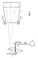
- the radiation transmitter 1 is a radiation receiver 3 assigned to the radiation emitted by the radiation transmitter 1 receives.
- This radiation receiver 3 is a transmitter 4 assigned to the position detector.
- the transmitter 4 is designed as an infrared transmitter, the light from Receiver 2 is converted into electrical signals. This electrical signals are sent to an evaluation device 11 (FIG 2) supplied, the resulting distance, the angle of incidence and determines the direction of radiation.
- the transmitter 4 is the Voltage supplied to a voltage source 5.
- the radiation receiver 3 and the Transmitter 4 on a holder 6 designed as a bite holder arranged.
- the position detector can be used as a magnetic, electromagnetic, optical, acoustic or mechanical Facility. Furthermore, a transmitter 4 of the position detector on the radiation transmitter 1 and a receiver 2 of the position detector assigned to the radiation receiver 3 his. In a further embodiment, for example Transmitter 4 is provided on the radiation transmitter 1 and sends a beam of rays, that of one assigned to the radiation receiver 3 Reference point reflected and from one at the radiation transmitter 1 provided receiver 2 is received.
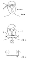
- FIG. 3 shows that the position detector not only a fixed one, as shown in FIG. 1 Assignment to radiation transmitter 3, but it can also directly and immediately assigned to the object under investigation his. 3 shows that the object under examination 7, for example the jaw, the magnets 8 are assigned, whose magnetic fields from magnetic field sensors 9 on the radiation receiver 3 and / or received at the radiation transmitter 1 and in electrical Signals are converted, which then the evaluation device 11 are supplied.
- Can also be used as a position detector find an electromagnetic device in which either the magnetic fields generated by coils or also can be detected by means of coils. Under the use of Changing magnetic fields can be used to measure static Interfering fields decoupled and the accuracy of the measurement be improved.
- the transmitter or receiver of the position detector can also on Examination object 7, for example on the head, in particular on the forehead (FIG. 4), or on a holding device 10 on Chin.
- the position detector By arranging the position detector at the greatest possible distance from the object under examination 7 the measurement accuracy can be increased significantly because at Moving the examination object 7 from the rest position larger leverage, i.e. a larger deflection is effective.
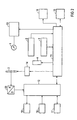
- An X-ray diagnostic device shows how results from FIG 2, in addition to the radiation transmitter 1, the Position detector 2.4 and the radiation receiver 3 another Control computer 11 and an image reconstruction computer 12.
- the control computer 11 controls a voltage supply device 13 for the radiation transmitter 1, the transmitter 4 of the position detector, a signal control device 14 for the Radiation receiver 3 and has a connection to the image reconstruction computer 12 to a memory 15 and a display 16 and receives signals from the receiver 2 of the position detector.
- the image reconstruction calculator 12 is another Memory 17, controls 18, an output unit 19 and an analog / digital converter assigned to that of the radiation receiver 3 outgoing signals converts.
- the control computer 11 calculates, as already explained, from the signals of the position detector the distance of the radiation transmitter 1 to the radiation receiver 3, the angle of incidence and the direction of incidence.
- the control computer 11 forms correction signals that either immediately or at a later date, after a temporary one Storage in memory 15, the image reconstruction computer 12 are supplied and used in the calculation a radiograph of the examination subject 7 is taken into account become. It is beneficial if dependent from the correction signals of the radiation transmitter 1 to the emission can be excited by radiation if predetermined limits of the correction signals not be exceeded. It can also be about the display 16 is a display by which communicated is that, for example, due to the movement of the object under examination 7 no blur-free picture taken can be.
- the examination object 7 is usually held by means of a bite holder, Forehead support or ear tips as rigid as possible X-ray device fixes what is perceived as unpleasant. A Movement of the examination object 7 leads to a Disturbance in the generated X-ray image, which is also undesirable is. It is also possible here, as already explained, the examination object 7 a certain freedom of movement give and its exact position and spatial orientation and their change during the recording process by measurement by means of a position detector. From the signals correction signals are then formed by the position detector, to before performing the tomographic blurring process the object details from the desired layer to be sharply imaged to assign the correct image content and the location of the desired layer of patient movement to track.
- the correction signals generated from the position measurements then affect the derivation intervals for the Single images / single image signals and their shift parallel and perpendicular to the tomographic scanning direction and also include rotations of the individual images / individual image signals, according to the direction and position of the layer image created differentiated changes in the magnification in the Single images / single image signals and the assembly effective single images / single image signals from several image strips / image signal strips according to the direction perpendicular lead intervals varying for the tomographic scanning direction.
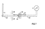
- This coupling device 21 has a first arm 22 which is connected to the radiation transmitter 1. On a second Arm 23 of the coupling device 21 is the radiation receiver 3 arranged.
- the examination object not shown in FIG. 7 is usually in the area of the radiation receiver 3 arranged.
- the first and second arms 22, 23 are about an axis of rotation 24 pivoted.
- the arms 22, 23 can be provided with a displacement transducer 25.
- Displacement transducers 25 are suitable, for example, rotary encoders or strain gauges.
- the coupling device 21 are two travel limiters 26 assigned to the adjustability in the embodiment limit the second arm 23.
- a spring element 27, for example, a leaf spring is provided is in connection with the arms 22,23, so is an elastic Adjustment of the arms 22, 23 relative to and around the Rotation axis 24 possible.
- the spring element 27 can advantageously so be carried out that there is a small deviation from the Shown assignment of radiation transmitter 1 and radiation receiver shown 3 to each other a small restoring torque and at large restoring moment causes a large deviation.
- the signals generated by the displacement sensor 25 are, as already explained, supplied to the evaluation device 11.
- the arms 22, 23 can also be adjusted by one Axis of rotation 24 vertical axis or via a gimbal Swivel joint can be adjustable in other spatial directions.
Description
Aus der WO 93/22 893 A1 ist eine Methode bekannt, mit der es möglich ist, eine Aufnahme eines Untersuchungsobjektes zu rekonstruieren, ohne das hierbei die Projektionswinkel α und die geometrische Anordnung von Strahlensender und Strahlenempfänger und die Fokalebene bekannt sind. Gemäß dieser Methode ist im Bereich des Strahlenempfängers eine Referenz aus strahlenabsorbierendem Material mit bekannter Größe und bekanntem Abstand zum Strahlenempfänger vorgesehen, die bei jeder Einzelprojektion auf den Strahlenempfänger projiziert wird. Aufgrund der örtlichen Abbildung der Referenz auf den Strahlenempfänger für jede Einzelprojektion kann die geometrische Anordnung und der zweidimensionale Projektionswinkel α ermittelt werden. Das Referenzobjekt ist hierbei an einem Aufbißhalter angeordnet, der auch den Strahlenempfänger trägt.A method is known from WO 93/22 893 A1 with which it it is possible to reconstruct an image of an examination object, without the projection angles α and the geometrical arrangement of the radiation transmitter and radiation receiver and the focal plane is known. According to this The method is a reference in the area of the radiation receiver made of radiation absorbing material of known size and Known distance to the radiation receiver provided at every single projection is projected onto the radiation receiver becomes. Due to the local mapping of the reference to the Radiation receivers for each individual projection can be geometrical Arrangement and the two-dimensional projection angle α can be determined. The reference object is on one Bite holder arranged, which is also the radiation receiver wearing.
Eine Halterung zum Positionieren eines Strahlensenders eines Röntgendiagnostikgeräts für Tomosynthese ist aus der DE 44 14 689 A1 bekannt. An die Halterung ist ein Tragarm angekoppelt, an dem - in Strahlungsrichtung gesehen - vor dem Untersuchungsobjekt ein kugelförmiges Referenzobjekt und hinter dem Untersuchungsobjekt ein Strahlenempfänger angeordnet sind. Über die Halterung wird zum einen der Abstand des Strahlensenders zum Referenzobjekt und zum Strahlenempfänger sowie der Winkel α eines vom Strahlensender emittierten Strahlenbündels zu einer Bezugsachse der Haltevorrichtung vorgegeben. Es ist ferner bekannt, die Strahlenquelle verstellbar in einem Gehäuse anzuordnen, an das eine Positionierungsvorrichtung für das Referenzobjekt und den Strahlenempfänger ankoppelbar ist.A bracket for positioning a radiation transmitter X-ray diagnostic equipment for tomosynthesis is from the DE 44 14 689 A1 known. A support arm is coupled to the bracket, on the - seen in the direction of radiation - in front of the Examination object a spherical reference object and behind a radiation receiver is arranged for the object under examination are. On the one hand, the distance of the Radiation transmitter to the reference object and to the radiation receiver and the angle α of one emitted by the radiation transmitter Beams to a reference axis of the holding device specified. It is also known that the radiation source is adjustable to be arranged in a housing to which a positioning device for the reference object and the radiation receiver can be coupled.
Bei der Tomosynthese müssen für alle der mehreren Projektionen (Einstrahlwinkel) die relativen Positionen und Lagen von Strahlensender, Untersuchungsobjekt und Strahlenempfänger bekannt sein. Wie bereits erläutert wird hierzu gemäß der WO 93/22 893 eine Auswertung von Bildsignalen vorgenommen, die beim Durchstrahlen des Referenzobjektes, das starr mit dem Strahlenempfänger verbunden ist, erzeugt werden. Hierbei ergibt sich beim Durchstrahlen des Untersuchungsobjektes allerdings eine unerwünschte Überlagerung durch das Referenzobjekt und es bedarf eines hohen Verarbeitungsaufwandes um die durch das Referenzobjekt verursachte Überlagerung aus den Bildsignalen heraus zu rechnen.In tomosynthesis, all of the multiple projections must be made (Angle of incidence) the relative positions and positions of radiation transmitter, examination object and radiation receiver be known. As already explained, according to the WO 93/22 893 carried out an evaluation of image signals, that when radiating through the reference object that is rigid with connected to the radiation receiver. in this connection results when the examination object is irradiated however, an undesired overlay by the reference object and it requires a lot of processing the overlay caused by the reference object from the To calculate image signals.
Gemäß der DE 44 14 689 A1 werden diese hierzu notwendigen Informationen durch die Konstruktion, d.h. durch die fest vorgegebenen Anordnung von Strahlensender, Untersuchungsobjekt und Strahlenempfänger vorgegeben. Aufgrund des hohen konstruktiven Aufwandes sind die Kosten eines derart ausgeführten Röntgendiagnostikgerätes erhöht. Zudem ist eine starre Fixierung des Untersuchungsobjektes gegeben was von diesem als unangenehm empfunden wird.According to DE 44 14 689 A1, these are necessary for this Information through the construction, i.e. through the feast predetermined arrangement of radiation transmitter, examination object and radiation receiver specified. Because of the high constructive effort is the cost of such a design X-ray diagnostic device increased. In addition, one rigid fixation of the object to be examined is given by this is felt to be uncomfortable.
Als nachteilig wird bei beiden Lösungsvorschlägen angesehen, daß Veränderungen der Lagebeziehung zwischen dem Aufnahmeobjekt und dem Strahlenempfänger nicht erfaßt werden.A disadvantage of both proposed solutions is that that changes in the positional relationship between the subject and the radiation receiver cannot be detected.
Aufgabe der Erfindung ist daher die weitere vorteilhafte Ausgestaltung des Röntgendiagnostikgerätes der eingangs genannten Art.The object of the invention is therefore the further advantageous embodiment of the X-ray diagnostic device of the aforementioned Art.
Die Aufgabe wird erfindungsgemäß durch den Gegenstand des Patentanspruches 1 gelöst.The object is achieved by the subject of Claim 1 solved.
Vorteil der Erfindung ist die Verwendung von Positionsdetektoren zum Erfassen der Zuordnung von Strahlensender zum Strahlenempfänger oder zum Untersuchungsobjekt, so daß keine mechanisch starre Kopplung vorgesehen werden muß oder ein Referenzobjekt sich durch Überlagerung störend auswirkt. The advantage of the invention is the use of position detectors to record the assignment of radiation transmitters to Radiation receiver or to the object under examination, so that none mechanically rigid coupling must be provided or a Reference object interferes with overlay.
Es ist vorteilhaft, wenn keine Kopplung, eine Kopplung zum Begrenzen der relativen Verstellung, oder eine elastische Kopplung zwischen dem Strahlensender und dem Strahlenempfänger oder dem Untersuchungsobjekt besteht, so daß auch dem Untersuchungsobjekt eine gewisse Bewegungsfreiheit erlaubt ist. Besonders vorteilhaft ist eine Kopplung, bei der bei einer geringen Abweichung von der Soll-Zuordnung ein kleines Rückstellmoment und bei einer großen Abweichung ein großes Rückstellmoment wirkt.It is advantageous if there is no coupling, a coupling to Limit the relative adjustment, or an elastic one Coupling between the radiation transmitter and the radiation receiver or the object under examination, so that the Examination object allows a certain freedom of movement is. A coupling is particularly advantageous in which a small deviation from the target assignment a small one Return torque and a large one if there is a large deviation Restoring moment acts.
Werden in Abhängigkeit von der Zuordnung des Strahlensenders zum Strahlenempfänger oder zum Untersuchungsobjekt Korrektursignale erzeugt, so ist es vorteilhaft, den Strahlensender zur Emission von Strahlung nur dann anregen zu können, wenn vorgegebene Grenzen der Korrektursignale nicht überschritten werden oder eine Anzeige erfolgt, wenn die Korrektursignale die vorgegebenen Grenzen überschreiten. Es wird somit sichergestellt, daß verwacklungsfreie Aufnahmen erhalten werden, wodurch die Strahlenbelastung durch wiederholtes Durchstrahlen des Untersuchungsobjektes zum Erhalt einwandfreier Aufnahmen reduziert ist.Are depending on the assignment of the radiation transmitter to the radiation receiver or to the examination object correction signals generated, it is advantageous to use the radiation transmitter to be able to stimulate the emission of radiation only if specified limits of the correction signals are not exceeded be displayed or when the correction signals exceed the given limits. This ensures that blur-free images are obtained, which results in repeated exposure to radiation of the object under examination to obtain perfect images is reduced.
Weitere Vorteile und Einzelheiten der Erfindung ergeben sich aus der nachfolgenden Beschreibung eines Ausführungsbeispieles anhand der Zeichnung in Verbindung mit den Unteransprüchen.Further advantages and details of the invention emerge from the following description of an embodiment based on the drawing in conjunction with the subclaims.
Es zeigt:
- FIG 1
- Ein Röntgendiagnostikgerät für Tomosynthese in prinzipieller Darstellung,
- FIG 2
- ein Blockschaltbild des Röntgendiagnostikgerätes nach FIG 1,
- FIG 3
- ein Ausführungsbeispiel zum Erfassen der Bewegung des Untersuchungsobjektes relativ zum Strahlenempfänger,
- FIG 4, FIG 5
- ein am Untersuchungsobjekt angeordneter Positionsdetektor,
- FIG 6
- eine Vorrichtung mit Positionsdetektoren nach der FIG 5 in einer Draufsicht und
- FIG 7
- eine Koppeleinrichtung des Röntgendiagnostikgeräts nach FIG 1.
- FIG. 1
- A basic X-ray diagnostic device for tomosynthesis,
- FIG 2
- 2 shows a block diagram of the X-ray diagnostic device according to FIG. 1,
- FIG 3
- one exemplary embodiment for detecting the movement of the examination object relative to the radiation receiver,
- FIG 4, FIG 5
- a position detector arranged on the examination object,
- FIG 6
- a device with position detectors according to FIG 5 in a plan view and
- FIG 7
- a coupling device of the X-ray diagnostic device according to FIG. 1.
In der FIG 1 ist ein Röntgendiagnostikgerät für Tomosynthese
dargestellt, das einen Strahlensender 1 aufweist, dem im Ausführungsbeispiel
ein Empfänger 2 eines Positionsdetektors zugeordnet
ist. Dem Strahlensender 1 ist ein Strahlenempfänger
3 zugeordnet, der die vom Strahlensender 1 ausgehende Strahlung
empfängt. Diesem Strahlenempfänger 3 ist ein Sender 4
des Positionsdetektors zugeordnet. Im Ausführungsbeispiel ist
der Sender 4 als Infrarotsender ausgeführt, dessen Licht vom
Empfänger 2 in elektrische Signale gewandelt wird. Diese
elektrischen Signale werden einer Auswerteeinrichtung 11
(FIG 2) zugeführt, die hieraus den Abstand, den Einstrahlwinkel
und die Einstrahlrichtung bestimmt. Dem Sender 4 wird die
Spannung einer Spannungsquelle 5 zugeführt. Im Ausführungsbeispiel
sind sowohl der Strahlenempfänger 3 als auch der
Sender 4 an einer als Aufbißhalter ausgeführten Halterung 6
angeordnet.1 shows an X-ray diagnostic device for tomosynthesis
shown, which has a radiation transmitter 1, in the embodiment
a
Im Rahmen der Erfindung kann der Positionsdetektor als magnetische,
elektromagnetische, optische, akustische oder mechanische
Einrichtung ausgeführt sein. Ferner kann ein Sender 4
des Positionsdetektors am Strahlensender 1 und ein Empfänger
2 des Positionsdetektors dem Strahlenempfänger 3 zugeordnet
sein. Bei einer weiteren Ausgestaltung ist beispielsweise der
Sender 4 am Strahlensender 1 vorgesehen und sendet ein Strahlenbündel,
das von einer dem Strahlenempfänger 3 zugeordneten
Referenzstelle reflektiert und von einem am Strahlensender 1
vorgesehenen Empfänger 2 empfangen wird.In the context of the invention, the position detector can be used as a magnetic,
electromagnetic, optical, acoustic or mechanical
Facility. Furthermore, a
Zwischen dem Strahlensender 1 und dem Strahlenempfänger 3
kann, wie in der FIG 1 gezeigt, keine Kopplung bestehen. Es
ist aber auch möglich, eine Kopplung zur Begrenzung der relativen
Verstellung oder eine elastische Kopplung derart vorzusehen,
daß dem Untersuchungsobjekt ein gewisser Bewegungsspielraum
eingeräumt wird. Besonders vorteilhaft ist es, wenn
die Kopplung so ausgeführt ist, daß bei einer geringen Abweichung
von einer Soll-Zuordnung ein kleines Rückstellmoment
und bei einer großen Abweichung ein großen Rückstellmoment
erzeugt wird.Between the radiation transmitter 1 and the
Aus den FIG 3, 4 und 5 geht hervor, daß der Positionsdetektor
nicht nur, wie dies in der FIG 1 dargestellt ist, eine feste
Zuordnung zum Strahlensender 3 haben, sondern er kann auch
dem Untersuchungsobjekt direkt und unmittelbar zugeordnet
sein. Aus der FIG 3 geht hervor, daß dem Untersuchungsobjekt
7, beispielsweise dem Kiefer, die Magnete 8, zugeordnet sind,
deren Magnetfelder von Magnetfeldsensoren 9 am Strahlenempfänger
3 und/oder am Strahlensender 1 empfangen und in elektrische
Signale gewandelt werden, die dann der Auswerteeinrichtung
11 zugeführt werden. Als Positionsdetektor kann auch
eine elektromagnetische Einrichtung Anwendung finden, bei der
entweder die Magnetfelder von Spulen erzeugt oder auch
mittels Spulen detektiert werden können. Unter Verwendung von
sich ändernden Magnetfeldern kann die Messung von statischen
Störfeldern entkoppelt und die Genauigkeit der Messung
verbessert werden.3, 4 and 5 show that the position detector
not only a fixed one, as shown in FIG. 1
Assignment to
Der Sender oder Empfänger des Positionsdetektors kann auch am
Untersuchungsobjekt 7, beispielsweise am Kopf, insbesondere
an der Stirn (FIG 4), oder an einer Halteeinrichtung 10 am
Kinn angeordnet sein. Durch die Anordnung des Positionsdetektors
in möglichst großem Abstand zum Untersuchungsobjekt 7
kann die Meßgenauigkeit erheblich erhöht werden, weil beim
Bewegen des Untersuchungsobjektes 7 aus der Ruhelage ein
größerer Hebel, d.h. eine größere Auslenkung wirksam ist.The transmitter or receiver of the position detector can also on
Eine erfindungsgemäße Röntgendiagnostikeinrichtung weist, wie
sich aus der FIG 2 ergibt, neben dem Strahlensender 1, dem
Positionsdetektor 2,4 und dem Strahlenempfänger 3 noch einen
Steuerrechner 11 und einen Bildrekonstruktionsrechner 12 auf.
Der Steuerrechner 11 steuert eine Spannungsversorgungseinrichtung
13 für den Strahlensender 1, den Sender 4 des Positionsdetektors,
eine Signalsteuereinrichtung 14 für den
Strahlenempfänger 3 und hat eine Verbindung zum Bildrekonstruktionsrechner
12 zu einem Speicher 15 und zu einer Anzeige
16 und empfängt Signale vom Empfänger 2 des Positionsdetektors.
Dem Bildrekonstruktionsrechner 12 ist ein weiterer
Speicher 17, Bedienelemente 18, eine Ausgabeeinheit 19 sowie
ein Analog-/Digital-Wandler zugeordnet, der die vom Strahlenempfänger
3 ausgehenden Signale wandelt. Der Steuerrechner 11
berechnet, wie bereits erläutert, aus den Signalen des Positionsdetektors
den Abstand des Strahlensenders 1 zum Strahlenempfänger
3, den Einstrahlwinkel und die Einstrahlrichtung.
Weicht die Ausrichtung von Strahlensender 1, Untersuchungsobjekt
7 und Strahlenempfänger 3 von einer Soll-Zuordung
ab, so bildet der Steuerrechner 11 Korrektursignale, die
entweder sofort oder zu einem späteren Zeitpunkt, nach vorübergehender
Speicherung im Speicher 15, dem Bildrekonstruktionsrechner
12 zugeführt werden und die bei der Berechnung
eines Durchstrahlungsbildes des Untersuchungsobjektes 7 berücksichtigt
werden. Es ist vorteilhaft, wenn in Abhängigkeit
von den Korrektursignalen der Strahlensender 1 zur Emission
von Strahlung anregbar ist, wenn vorgegebene Grenzen der Korrektursignale
nicht überschritten werden. Es kann auch über
die Anzeige 16 eine Anzeige erfolgen, durch die mitgeteilt
wird, daß beispielsweise aufgrund der Bewegung des Untersuchungsobjektes
7 keine verwacklungsfreie Aufnahme erstellt
werden kann.An X-ray diagnostic device according to the invention shows how
results from FIG 2, in addition to the radiation transmitter 1, the
Position detector 2.4 and the
Bei Panorama-Röntgengeräten zur Erstellung von Schichtaufnahmen
wird das Untersuchungsobjekt 7 üblicherweise mittels Aufbißhalter,
Stirnstütze oder Ohroliven möglichst starr am
Röntgengerät fixiert, was als unangenehm empfunden wird. Eine
Bewegung des Untersuchungsobjektes 7 führt allerdings zu einer
Störung im erzeugten Röntgenbild, was ebenfalls unerwünscht
ist. Auch hier ist es möglich, wie bereits erläutert,
dem Untersuchungsobjekt 7 eine gewisse Bewegungsfreiheit zu
geben und seine genaue Position und räumliche Orientierung
und deren Änderung während des Aufnahmeablaufes durch Messung
mittels eines Positionsdetektors zu erfassen. Aus den Signalen
des Positionsdetektors werden dann Korrektursignale gebildet,
um vor der Durchführung des tomographischen Verwischungsprozesses
den Objektdetails aus der gewünschten,
scharf abzubildenden Schicht, die richtigen Bildinhalte zuzuordnen
und die Lage der gewünschten Schicht der Patientenbewegung
nachzuführen. Voraussetzung hierfür ist, daß die
entstehenden, sich entsprechend der tomographischen Abtastbewegung
des Röntgengerätes laufend ändernden Bildsignale in
feinen Schritten erfaßt und zunächst gespeichert werden und
erst nach Vorliegen der kompletten für einen Objektbereich
relevanten Bildsignale die Verwischung rechnerisch entsprechend
der in diesem Objektbereich gewünschten Schichtlage zu
erstellen. Die aus den Positionsmessungen erzeugten Korrektursignale
beeinflussen dann die Ableitungsintervalle für die
Einzelbilder/Einzelbildsignale sowie deren Verschiebung
parallel und senkrecht zur tomographischen Abtastrichtung und
beinhalten auch Rotationen der Einzelbilder/Einzelbildsignale,
nach Richtung und Position der erstellten Schichtaufnahme
differenzierte Änderungen des Vergrößerungsmaßstabes in den
Einzelbildern/Einzelbildsignalen und das Zusammensetzen
effektiver Einzelbilder/Einzelbildsignale aus mehreren Bildstreifen/Bildsignalstreifen
gemäß in der Richtung senkrecht
zur tomographischen Abtastrichtung variierender Ableitintervalle.For panoramic X-ray machines for taking layer pictures
the
In der FIG 7 ist eine Koppeleinrichtung 21 in prinzipieller
Weise dargestellt, die die relative Verstellung zwischen dem
Strahlensender 1 und dem Strahlenempfänger 3 oder dem Untersuchungsobjekt
7 oder zwischen dem Strahlenempfänger 3 und
dem Untersuchungsobjekt 7 begrenzt oder elastisch koppelt.
Diese Koppeleinrichtung 21 weist einen ersten Arm 22 auf, der
mit dem Strahlensender 1 in Verbindung steht. An einem zweiten
Arm 23 der Koppeleinrichtung 21 ist der Strahlenempfänger
3 angeordnet. Das in der FIG 7 nicht gezeigte Untersuchungsobjekt
ist üblicherweise im Bereich des Strahlenempfängers 3
angeordnet. Der erste und zweite Arm 22,23 sind um eine Drehachse
24 schwenkbar gelagert. Zur Erfassung der Verschwenkung
der Arme 22,23 kann ein Wegaufnehmer 25 vorgesehen sein. Als
Wegaufnehmer 25 eignen sich beispielsweise Rotationsencoder
oder Dehnmeßstreifen. Der Koppeleinrichtung 21 sind zwei Wegbegrenzer
26 zugeordnet, die im Ausführungsbeispiel die Verstellbarkeit
des zweiten Armes 23 begrenzen. Ist ein Federelement
27, beispielsweise eine Blattfeder vorgesehen, das
mit den Armen 22,23 in Verbindung steht, so ist eine elastische
Verstellung der Arme 22,23 relativ zueinander und um die
Drehachse 24 möglich. Das Federelement 27 kann vorteilhaft so
ausgeführt sein, daß es bei einer kleinen Abweichung von der
gezeigten Soll-Zuordnung von Strahlensender 1 und Strahlenempfänger
3 zueinander ein kleines Rückstellmoment und bei
einer großen Abweichung ein großes Rückstellmoment bewirkt.
Die vom Wegaufnehmer 25 erzeugten Signale werden, wie bereits
erläutert, der Auswerteeinrichtung 11 zugeführt. Im Rahmen
der Erfindung können die Arme 22,23 auch noch um eine zur
Drehachse 24 senkrechte Achse oder über ein kardanisches
Drehgelenk in anderen Raumrichtungen verstellbar sein.7 shows a coupling device 21 in principle
Shown way, the relative adjustment between the
Radiation transmitter 1 and the
Claims (6)
- X-ray diagnostic apparatus for tomosynthesis, having a radiation transmitter (1) and a radiation receiver (3) which, for the generation of tomosynthesis recordings of an object (7) under examination, are adjustably mounted such that when the object (7) under examination is transilluminated from different directions, in each case signals can be derived at the radiation receiver (3) and are fed to an image-generating device (12) in order to calculate a tomosynthesis recording of the object (7) under examination,
having at least one position detector (2, 4) to register the relationship between the radiation transmitter (1) and the radiation receiver (3) or the object (7) under examination, or of radiation receiver (3) and object (7) under examination, and
having an evaluation device (11) to evaluate the signals from the position detector (2, 4),
the position detector (2, 4) being arranged on the radiation transmitter (1), on the radiation receiver (3) or on the object (7) under examination,
correction signals being generated if the relationship between the radiation transmitter (1) and the radiation receiver (3) or the object (7) under examination, or between the radiation receiver (3) and the object (7) under examination, deviates from a desired relationship and
the correction signals being fed to the image generating device (12). - X-ray diagnostic apparatus according to Claim 1, the position detector (2, 4) being implemented as a magnetic, electromagnetic, optical, acoustic or mechanical device and
the transmitter or the receiver (2, 4) of the position detector being mounted on the radiation receiver (3) or on the object (7) under examination or on a holding device (10) which is connected to the latter,
the receiver or the transmitter (4, 2) being arranged on the radiation transmitter (1). - X-ray diagnostic apparatus according to Claim 1 or 2, there being no coupling, coupling to limit the relative adjustment, or elastic coupling between the radiation transmitter (1) and the radiation receiver (3) or the object (7) under examination.
- X-ray diagnostic apparatus according to Claim 3, the coupling being implemented such that a small restoring torque acts in the event of a small deviation from the desired relationship and a large restoring torque acts in the event of a large deviation.
- X-ray diagnostic apparatus according to one of Claims 1 to 4, the radiation transmitter (1) being able to be stimulated, depending on the correction signals, to emit radiation if prescribed limits on the correction signals are not exceeded.
- X-ray diagnostic apparatus according to one of Claims 1 to 5, an indication being given if the correction signals exceed the prescribed limits.
Applications Claiming Priority (2)
| Application Number | Priority Date | Filing Date | Title |
|---|---|---|---|
| DE19619925 | 1996-05-17 | ||
| DE19619925A DE19619925C2 (en) | 1996-05-17 | 1996-05-17 | X-ray diagnostic device for tomosynthesis |
Publications (2)
| Publication Number | Publication Date |
|---|---|
| EP0807404A1 EP0807404A1 (en) | 1997-11-19 |
| EP0807404B1 true EP0807404B1 (en) | 2003-03-26 |
Family
ID=7794577
Family Applications (1)
| Application Number | Title | Priority Date | Filing Date |
|---|---|---|---|
| EP97107307A Expired - Lifetime EP0807404B1 (en) | 1996-05-17 | 1997-05-02 | Diagnostic x-ray apparatus for tomosynthesis |
Country Status (4)
| Country | Link |
|---|---|
| US (1) | US5828722A (en) |
| EP (1) | EP0807404B1 (en) |
| JP (1) | JPH1043179A (en) |
| DE (2) | DE19619925C2 (en) |
Families Citing this family (78)
| Publication number | Priority date | Publication date | Assignee | Title |
|---|---|---|---|---|
| DE69738156T2 (en) | 1997-09-27 | 2008-06-12 | Brainlab Ag | Method and device for taking a three-dimensional image of a body part |
| US6289235B1 (en) * | 1998-03-05 | 2001-09-11 | Wake Forest University | Method and system for creating three-dimensional images using tomosynthetic computed tomography |
| US6081577A (en) * | 1998-07-24 | 2000-06-27 | Wake Forest University | Method and system for creating task-dependent three-dimensional images |
| US6540399B1 (en) | 1999-02-26 | 2003-04-01 | Dentsply Research & Development Corp. | Bite block for dental X-Ray procedures |
| DE19912854A1 (en) * | 1999-03-22 | 2000-10-05 | Sirona Dental Systems Gmbh | Process for correcting the magnification factor in digital X-ray images |
| WO2001027877A1 (en) * | 1999-10-14 | 2001-04-19 | Centrum für Dentale Innovationen GmbH | Method for sectional imaging and sectional imaging device |
| US6381301B1 (en) | 1999-12-01 | 2002-04-30 | Ronald E. Massie | Dental and orthopedic densitometry modeling system and method |
| US8126112B2 (en) * | 1999-12-01 | 2012-02-28 | Massie Ronald E | Osseo classification system and method |
| US8073101B2 (en) * | 1999-12-01 | 2011-12-06 | Massie Ronald E | Digital modality modeling for medical and dental applications |
| US6944262B2 (en) * | 1999-12-01 | 2005-09-13 | Massie Ronald E | Dental and orthopedic densitometry modeling system and method |
| US6671349B1 (en) | 2000-11-13 | 2003-12-30 | Olganix Corporation | Tomosynthesis system and registration method |
| JP3785576B2 (en) * | 2002-04-24 | 2006-06-14 | 株式会社モリタ製作所 | Subject blur correction means and medical X-ray imaging apparatus using the same |
| DE10250005B4 (en) * | 2002-10-25 | 2009-03-19 | Sirona Dental Systems Gmbh | Bite device for use with a panoramic X-ray device |
| US10638994B2 (en) | 2002-11-27 | 2020-05-05 | Hologic, Inc. | X-ray mammography with tomosynthesis |
| US7616801B2 (en) | 2002-11-27 | 2009-11-10 | Hologic, Inc. | Image handling and display in x-ray mammography and tomosynthesis |
| US7123684B2 (en) | 2002-11-27 | 2006-10-17 | Hologic, Inc. | Full field mammography with tissue exposure control, tomosynthesis, and dynamic field of view processing |
| US8565372B2 (en) | 2003-11-26 | 2013-10-22 | Hologic, Inc | System and method for low dose tomosynthesis |
| US8571289B2 (en) | 2002-11-27 | 2013-10-29 | Hologic, Inc. | System and method for generating a 2D image from a tomosynthesis data set |
| US7577282B2 (en) | 2002-11-27 | 2009-08-18 | Hologic, Inc. | Image handling and display in X-ray mammography and tomosynthesis |
| US7433507B2 (en) * | 2003-07-03 | 2008-10-07 | Ge Medical Systems Global Technology Co. | Imaging chain for digital tomosynthesis on a flat panel detector |
| FI118356B (en) * | 2004-07-22 | 2007-10-15 | Planmeca Oy | Arrangements in connection with intraoral X-ray imaging |
| US7319396B2 (en) * | 2004-08-16 | 2008-01-15 | Abr, Llc | RFID transducer alignment system |
| US7662082B2 (en) | 2004-11-05 | 2010-02-16 | Theragenics Corporation | Expandable brachytherapy device |
| EP1815388B1 (en) | 2004-11-15 | 2013-03-06 | Hologic, Inc. | Matching geometry generation and display of mammograms and tomosynthesis images |
| US7869563B2 (en) | 2004-11-26 | 2011-01-11 | Hologic, Inc. | Integrated multi-mode mammography/tomosynthesis x-ray system and method |
| US7991242B2 (en) | 2005-05-11 | 2011-08-02 | Optosecurity Inc. | Apparatus, method and system for screening receptacles and persons, having image distortion correction functionality |
| US20090174554A1 (en) | 2005-05-11 | 2009-07-09 | Eric Bergeron | Method and system for screening luggage items, cargo containers or persons |
| US10008184B2 (en) | 2005-11-10 | 2018-06-26 | Hologic, Inc. | System and method for generating a 2D image using mammography and/or tomosynthesis image data |
| US8079946B2 (en) | 2005-11-18 | 2011-12-20 | Senorx, Inc. | Asymmetrical irradiation of a body cavity |
| JP5554927B2 (en) | 2006-02-15 | 2014-07-23 | ホロジック, インコーポレイテッド | Breast biopsy and needle localization using tomosynthesis system |
| US7899232B2 (en) | 2006-05-11 | 2011-03-01 | Optosecurity Inc. | Method and apparatus for providing threat image projection (TIP) in a luggage screening system, and luggage screening system implementing same |
| WO2007149402A2 (en) * | 2006-06-16 | 2007-12-27 | Gendex Corporation | Positioning system for dental intra-oral x-ray apparatus |
| US8494210B2 (en) | 2007-03-30 | 2013-07-23 | Optosecurity Inc. | User interface for use in security screening providing image enhancement capabilities and apparatus for implementing same |
| US20080032257A1 (en) * | 2006-08-01 | 2008-02-07 | Muckler Michael P | X-ray reference device and method of use |
| US7744279B2 (en) * | 2006-11-02 | 2010-06-29 | Carestream Health, Inc. | Orientation sensing apparatus for radiation imaging system |
| DE102007008962A1 (en) * | 2007-02-21 | 2008-08-28 | Sirona Dental Systems Gmbh | Small dental X-ray device and method for positioning an X-ray source |
| US7630533B2 (en) | 2007-09-20 | 2009-12-08 | Hologic, Inc. | Breast tomosynthesis with display of highlighted suspected calcifications |
| US20090086926A1 (en) * | 2007-09-27 | 2009-04-02 | Carestream Health, Inc. | Exposure centering apparatus for imaging system |
| US7792245B2 (en) | 2008-06-24 | 2010-09-07 | Hologic, Inc. | Breast tomosynthesis system with shifting face shield |
| US7991106B2 (en) | 2008-08-29 | 2011-08-02 | Hologic, Inc. | Multi-mode tomosynthesis/mammography gain calibration and image correction using gain map information from selected projection angles |
| KR100920848B1 (en) * | 2008-11-17 | 2009-10-08 | 최영진 | Film holder with angle indicator for intraoral radiography and film supporting part of the film holder |
| US9579524B2 (en) | 2009-02-11 | 2017-02-28 | Hologic, Inc. | Flexible multi-lumen brachytherapy device |
| US9248311B2 (en) | 2009-02-11 | 2016-02-02 | Hologic, Inc. | System and method for modifying a flexibility of a brachythereapy catheter |
| US10207126B2 (en) | 2009-05-11 | 2019-02-19 | Cytyc Corporation | Lumen visualization and identification system for multi-lumen balloon catheter |
| WO2011043838A1 (en) | 2009-10-08 | 2011-04-14 | Hologic, Inc . | Needle breast biopsy system and method of use |
| WO2011141763A1 (en) * | 2010-05-12 | 2011-11-17 | Trophy | Alignment apparatus for dental intraoral radiography |
| US9352172B2 (en) | 2010-09-30 | 2016-05-31 | Hologic, Inc. | Using a guide member to facilitate brachytherapy device swap |
| US9668711B2 (en) | 2010-10-05 | 2017-06-06 | Hologic, Inc | X-ray breast tomosynthesis enhancing spatial resolution including in the thickness direction of a flattened breast |
| CN103179906B (en) | 2010-10-05 | 2016-04-06 | 霍洛吉克公司 | There is CT pattern, multilamellar analyses image pickup mode and the erect-type X-ray breast imaging of mammary gland image pickup mode |
| US20120133600A1 (en) | 2010-11-26 | 2012-05-31 | Hologic, Inc. | User interface for medical image review workstation |
| US10342992B2 (en) | 2011-01-06 | 2019-07-09 | Hologic, Inc. | Orienting a brachytherapy applicator |
| EP2684157B1 (en) | 2011-03-08 | 2017-12-13 | Hologic Inc. | System and method for dual energy and/or contrast enhanced breast imaging for screening, diagnosis and biopsy |
| US8670521B2 (en) * | 2011-06-02 | 2014-03-11 | Carestream Health, Inc. | Method for generating an intraoral volume image |
| WO2013036735A1 (en) | 2011-09-07 | 2013-03-14 | Rapiscan Systems, Inc. | X-ray inspection system that integrates manifest data with imaging/detection processing |
| EP2782505B1 (en) | 2011-11-27 | 2020-04-22 | Hologic, Inc. | System and method for generating a 2d image using mammography and/or tomosynthesis image data |
| WO2013123091A1 (en) | 2012-02-13 | 2013-08-22 | Hologic, Inc. | System and method for navigating a tomosynthesis stack using synthesized image data |
| EP2967479B1 (en) | 2013-03-15 | 2018-01-31 | Hologic Inc. | Tomosynthesis-guided biopsy in prone |
| US20160284241A1 (en) * | 2013-08-29 | 2016-09-29 | University Of Washington Through Its Center For Commercialization | Methods and Systems for Simulating an X-Ray Dental Image |
| JP6220253B2 (en) * | 2013-12-13 | 2017-10-25 | 株式会社吉田製作所 | Dental X-ray system |
| ES2943561T3 (en) | 2014-02-28 | 2023-06-14 | Hologic Inc | System and method for generating and visualizing tomosynthesis image blocks |
| US9408581B2 (en) * | 2014-03-07 | 2016-08-09 | Elwha Llc | Systems, devices, and methods for lowering dental x-ray dosage including feedback sensors |
| US9782136B2 (en) | 2014-06-17 | 2017-10-10 | The University Of North Carolina At Chapel Hill | Intraoral tomosynthesis systems, methods, and computer readable media for dental imaging |
| US10980494B2 (en) | 2014-10-20 | 2021-04-20 | The University Of North Carolina At Chapel Hill | Systems and related methods for stationary digital chest tomosynthesis (s-DCT) imaging |
| US10835199B2 (en) | 2016-02-01 | 2020-11-17 | The University Of North Carolina At Chapel Hill | Optical geometry calibration devices, systems, and related methods for three dimensional x-ray imaging |
| EP3420563A4 (en) | 2016-02-22 | 2020-03-11 | Rapiscan Systems, Inc. | Systems and methods for detecting threats and contraband in cargo |
| US11076820B2 (en) | 2016-04-22 | 2021-08-03 | Hologic, Inc. | Tomosynthesis with shifting focal spot x-ray system using an addressable array |
| US10631799B2 (en) * | 2016-12-07 | 2020-04-28 | Harris Corporation | Dental image collection device providing optical alignment features and related system and methods |
| US11455754B2 (en) | 2017-03-30 | 2022-09-27 | Hologic, Inc. | System and method for synthesizing low-dimensional image data from high-dimensional image data using an object grid enhancement |
| CN110662489A (en) | 2017-03-30 | 2020-01-07 | 豪洛捷公司 | System and method for targeted object enhancement to generate synthetic breast tissue images |
| US11403483B2 (en) | 2017-06-20 | 2022-08-02 | Hologic, Inc. | Dynamic self-learning medical image method and system |
| WO2019035064A1 (en) | 2017-08-16 | 2019-02-21 | Hologic, Inc. | Techniques for breast imaging patient motion artifact compensation |
| EP3449835B1 (en) | 2017-08-22 | 2023-01-11 | Hologic, Inc. | Computed tomography system and method for imaging multiple anatomical targets |
| WO2019040056A1 (en) | 2017-08-23 | 2019-02-28 | Carestream Dental Technology Topco Limited | Dental chair-side tomosynthesis system |
| US10307233B1 (en) * | 2018-01-09 | 2019-06-04 | Albert Davydov | Method for utilizing a mandibular c-clamp to identify a fixed point of reference on a human jaw |
| US11090017B2 (en) | 2018-09-13 | 2021-08-17 | Hologic, Inc. | Generating synthesized projection images for 3D breast tomosynthesis or multi-mode x-ray breast imaging |
| EP3832689A3 (en) | 2019-12-05 | 2021-08-11 | Hologic, Inc. | Systems and methods for improved x-ray tube life |
| US11471118B2 (en) | 2020-03-27 | 2022-10-18 | Hologic, Inc. | System and method for tracking x-ray tube focal spot position |
| US11786191B2 (en) | 2021-05-17 | 2023-10-17 | Hologic, Inc. | Contrast-enhanced tomosynthesis with a copper filter |
Family Cites Families (7)
| Publication number | Priority date | Publication date | Assignee | Title |
|---|---|---|---|---|
| US4211927A (en) * | 1978-11-24 | 1980-07-08 | Cgr Medical Corporation | Computerized tomography system |
| DE3808009C2 (en) * | 1987-03-13 | 1990-11-29 | Kabushiki Kaisha Morita Seisakusho, Kyoto, Jp | DEVICE FOR POSITIONING THE PATIENT IN A MEDICAL PANORAMIC X-RAY RECEIVING DEVICE |
| US5113424A (en) * | 1991-02-04 | 1992-05-12 | University Of Medicine & Dentistry Of New Jersey | Apparatus for taking radiographs used in performing dental subtraction radiography with a sensorized dental mouthpiece and a robotic system |
| US5359637A (en) * | 1992-04-28 | 1994-10-25 | Wake Forest University | Self-calibrated tomosynthetic, radiographic-imaging system, method, and device |
| US5629972A (en) * | 1993-05-18 | 1997-05-13 | Research Foundation Of State University Of New York | Intraoral radiograph alignment device |
| DE4414689C2 (en) * | 1994-04-26 | 1996-08-29 | Siemens Ag | X-ray diagnostic device |
| US5463669A (en) * | 1994-09-08 | 1995-10-31 | Kaplan; Jerome I. | Dental X-ray alignment system |
-
1996
- 1996-05-17 DE DE19619925A patent/DE19619925C2/en not_active Expired - Fee Related
-
1997
- 1997-05-02 EP EP97107307A patent/EP0807404B1/en not_active Expired - Lifetime
- 1997-05-02 DE DE59709594T patent/DE59709594D1/en not_active Expired - Fee Related
- 1997-05-14 US US08/856,147 patent/US5828722A/en not_active Expired - Fee Related
- 1997-05-15 JP JP9125126A patent/JPH1043179A/en active Pending
Also Published As
| Publication number | Publication date |
|---|---|
| DE19619925C2 (en) | 1999-09-09 |
| EP0807404A1 (en) | 1997-11-19 |
| JPH1043179A (en) | 1998-02-17 |
| DE59709594D1 (en) | 2003-04-30 |
| DE19619925A1 (en) | 1997-11-20 |
| US5828722A (en) | 1998-10-27 |
Similar Documents
| Publication | Publication Date | Title |
|---|---|---|
| EP0807404B1 (en) | Diagnostic x-ray apparatus for tomosynthesis | |
| DE69738156T2 (en) | Method and device for taking a three-dimensional image of a body part | |
| DE19950793B4 (en) | X-ray device and method for determining imaging parameters | |
| DE4414689C2 (en) | X-ray diagnostic device | |
| EP0910990B1 (en) | X-ray apparatus | |
| DE19936408B4 (en) | Mobile X-ray machine | |
| DE69926195T2 (en) | Apparatus and method for imaging | |
| DE102005030285B4 (en) | Computed tomography device and method for a computed tomography device with a marking means for positionally accurate marking of an intervention position by means of a laser beam on an object to be examined | |
| EP2082687B1 (en) | Overlaid presentation of exposures | |
| EP0910989A1 (en) | Radiographic apparatus | |
| DE112010003822B4 (en) | Apparatus and method for imaging in the dental field by means of X-rays | |
| DE102007019827A1 (en) | System and method for determining the position of an instrument | |
| EP0807405A1 (en) | Method for producing tomosynthetic images | |
| DE10215808A1 (en) | Surgical intervention navigation recording method in which a coordinate transform is calculated between an X-ray calibration phantom coordinate system and a position capture system using X-ray positive markers | |
| DE102005034518A1 (en) | Computed Tomography Dose Indexing Phantom Selection for Dose Documentation | |
| EP1852822A2 (en) | Generation of a three-dimensional medical image with independent positioning of emission source and detector | |
| DE10206190A1 (en) | Method and device for generating a volume data set | |
| EP0668741B1 (en) | Process and device for acceptance and regular testing of filmless dental radiographic equipment | |
| DE10234465A1 (en) | X-ray sectional-imaging method in which the height of a sectional image is set using a camera arrangement for imaging the patient from the side so that a reference marking can be made on a reference image | |
| DE102013200329B4 (en) | Method and device for misalignment correction for imaging methods | |
| WO2010136517A1 (en) | Imaging system for producing a 3-d data set and method for the operation thereof | |
| EP1003420B1 (en) | X-ray examination unit for tomosynthesis | |
| DE102009047867A1 (en) | Method for correcting truncated projection data | |
| EP2247241B1 (en) | Medical radiological device and radiological system | |
| DE2646521A1 (en) | PROCEDURE FOR CALIBRATING AN AXIAL TOMOGRAPHIC SCANNER |
Legal Events
| Date | Code | Title | Description |
|---|---|---|---|
| PUAI | Public reference made under article 153(3) epc to a published international application that has entered the european phase |
Free format text: ORIGINAL CODE: 0009012 |
|
| AK | Designated contracting states |
Kind code of ref document: A1 Designated state(s): DE FI FR IT SE |
|
| RAP1 | Party data changed (applicant data changed or rights of an application transferred) |
Owner name: SIRONA DENTAL SYSTEMS GMBH & CO.KG |
|
| 17P | Request for examination filed |
Effective date: 19980519 |
|
| RAP1 | Party data changed (applicant data changed or rights of an application transferred) |
Owner name: SIRONA DENTAL SYSTEMS GMBH |
|
| GRAH | Despatch of communication of intention to grant a patent |
Free format text: ORIGINAL CODE: EPIDOS IGRA |
|
| GRAH | Despatch of communication of intention to grant a patent |
Free format text: ORIGINAL CODE: EPIDOS IGRA |
|
| GRAA | (expected) grant |
Free format text: ORIGINAL CODE: 0009210 |
|
| AK | Designated contracting states |
Designated state(s): DE FI FR IT SE |
|
| PG25 | Lapsed in a contracting state [announced via postgrant information from national office to epo] |
Ref country code: IT Free format text: LAPSE BECAUSE OF FAILURE TO SUBMIT A TRANSLATION OF THE DESCRIPTION OR TO PAY THE FEE WITHIN THE PRESCRIBED TIME-LIMIT;WARNING: LAPSES OF ITALIAN PATENTS WITH EFFECTIVE DATE BEFORE 2007 MAY HAVE OCCURRED AT ANY TIME BEFORE 2007. THE CORRECT EFFECTIVE DATE MAY BE DIFFERENT FROM THE ONE RECORDED. Effective date: 20030326 Ref country code: FR Free format text: LAPSE BECAUSE OF FAILURE TO SUBMIT A TRANSLATION OF THE DESCRIPTION OR TO PAY THE FEE WITHIN THE PRESCRIBED TIME-LIMIT Effective date: 20030326 Ref country code: FI Free format text: LAPSE BECAUSE OF FAILURE TO SUBMIT A TRANSLATION OF THE DESCRIPTION OR TO PAY THE FEE WITHIN THE PRESCRIBED TIME-LIMIT Effective date: 20030326 |
|
| REF | Corresponds to: |
Ref document number: 59709594 Country of ref document: DE Date of ref document: 20030430 Kind code of ref document: P |
|
| PG25 | Lapsed in a contracting state [announced via postgrant information from national office to epo] |
Ref country code: SE Free format text: LAPSE BECAUSE OF FAILURE TO SUBMIT A TRANSLATION OF THE DESCRIPTION OR TO PAY THE FEE WITHIN THE PRESCRIBED TIME-LIMIT Effective date: 20030626 |
|
| PG25 | Lapsed in a contracting state [announced via postgrant information from national office to epo] |
Ref country code: DE Free format text: LAPSE BECAUSE OF NON-PAYMENT OF DUE FEES Effective date: 20031202 |
|
| PLBE | No opposition filed within time limit |
Free format text: ORIGINAL CODE: 0009261 |
|
| STAA | Information on the status of an ep patent application or granted ep patent |
Free format text: STATUS: NO OPPOSITION FILED WITHIN TIME LIMIT |
|
| EN | Fr: translation not filed | ||
| 26N | No opposition filed |
Effective date: 20031230 |